 Tim
TimThe assembled PCBs arrived after just 11 days. This is a short summary of the circuit characterization.
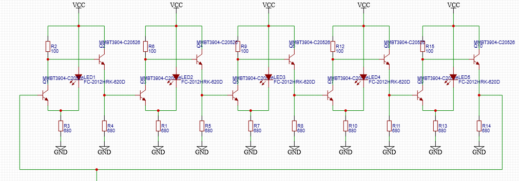
The full circuit of the five stage ring oscillator is shown above. I used MMTBH10 HF-Transistors in the actual built instead of the MMBT3904 that are shown in the circuit diagram. Since the source follow provides a low impedance output, I did not add an additional output driver and attached the scope directly to the output of the rightmost inverter.
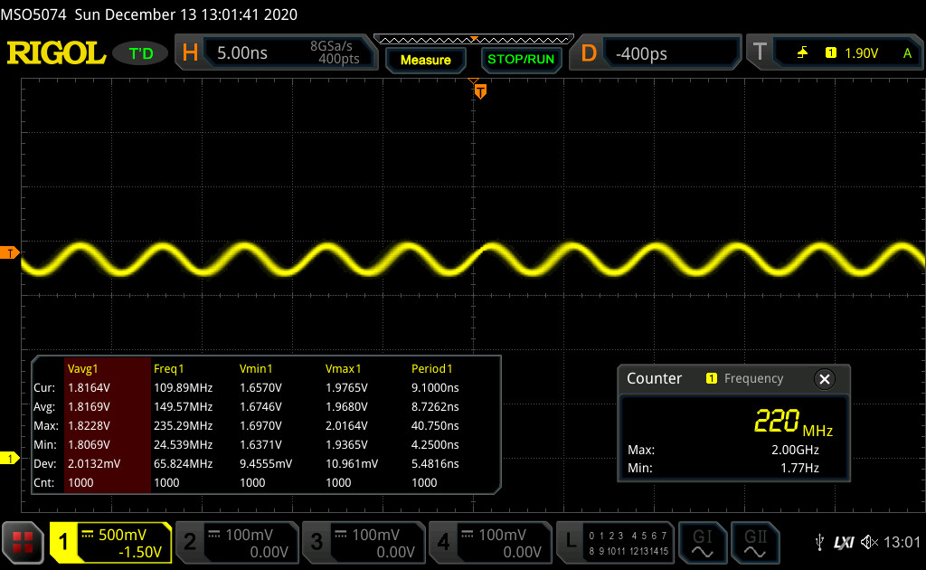
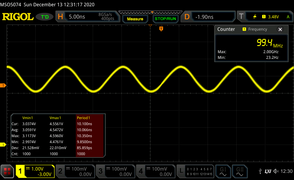
The two trace above show the ring oscillator at VDD=2.7V, the minimum voltage where it oscillates and at 5V.
| Vdd [V] | Idd [mA] | Vavg [V] | Vmin [V] | Vmax [V] | Swing [V] | Freq [MHz] | tpd [ns] |
| 2.7 | 18 | 1.81 | 1.68 | 1.95 | 0.27 | 222 | 0.45 |
| 3 | 22 | 2.08 | 1.92 | 2.25 | 0.33 | 213 | 0.46 |
| 3.5 | 28 | 2.57 | 2.41 | 2.72 | 0.31 | 176 | 0.56 |
| 4 | 35 | 2.96 | 2.65 | 3.25 | 0.6 | 144 | 0.69 |
| 4.5 | 42 | 3.38 | 2.9 | 3.85 | 0.95 | 115 | 0.86 |
| 5 | 47 | 3.82 | 3.08 | 4.54 | 1.46 | 100 | 1 |
Detailed measuremt results are shown in the table above. A minimum of 2.7V is needed for the oscillator to start oscillating. This seems to be governed by the forward voltage of the (red) LEDs. At this supply voltage there is very little voltage swing at the summing node of the differential pair, meaning that the inverter essentially works as a common emitter amplifier. At 450 ps, the extracted tdp is quite low, but it's arguable wether we are seeing digital switching. The output looks like a clean sine. One issue may be that the impedance of the scope probe is too low at the harmonics and is remove any edges. I need to look into an impedance matched set up.
Going to higher frequencies we see an increase in output voltage swing, but a reduction of frequency. At 5V the tpd is still at a respectable 1000 ps.
Discussions
Become a Hackaday.io Member
Create an account to leave a comment. Already have an account? Log In.