 David Tucker
I have been trying to work out how to use Fusion 360 to generate laser cut files. At first I tried just drawing the cut file as a 2D drawing then exporting as a dfx file. However LightBurn takes all your reference lines as cut lines, leaving a lot of cleanup and making it difficult to later modify the layout if needed.

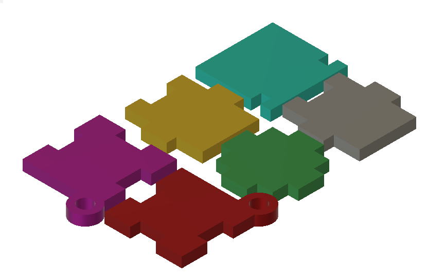
Recently I came across this article from Core Electronics and it has pointed me in a better direction. They generate a 3D object then flatten it out using the align then move tools. Finally they create a new 2D sketch and project the face of the boxes onto it to make a simplified drawing. This is much nicer, it lets you use all the tools available in Fusion when designing. And the output does not require any cleanup so that is a win as well.
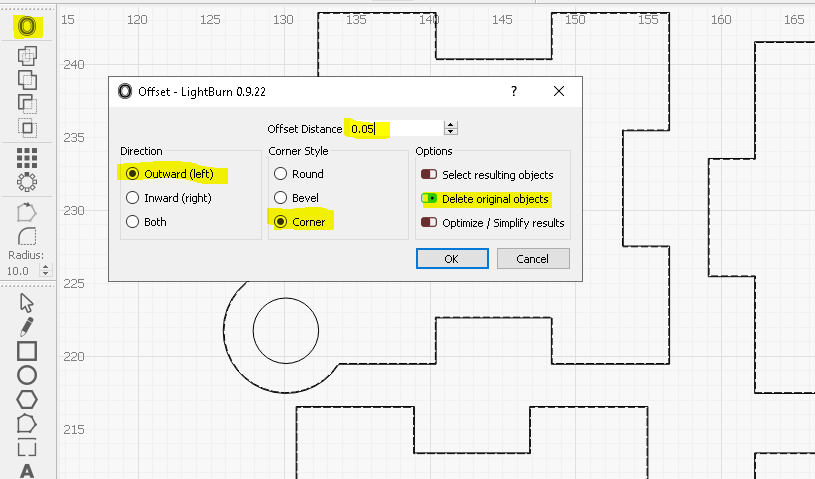
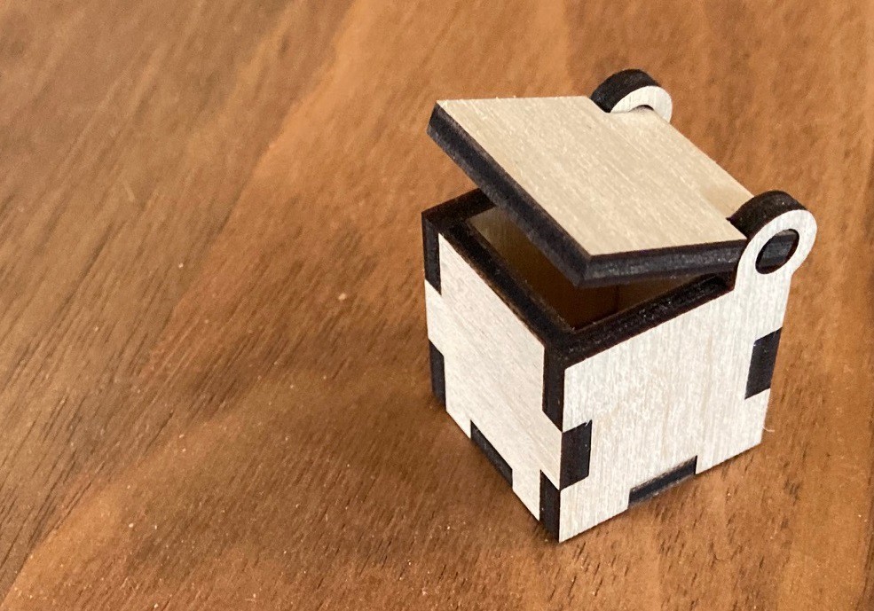
One trick I'm experimenting with in LightBurn is to use the offset feature to take care of the kerf (width of the cut). This increases the size of your design by the given amount, so when the laser cuts the excess off you should get a final result that is the exact size you originally designed. This allows you to do all the design work in Fusion without worrying about the kerf. Keep in mind that if your laser removes 0.1 mm of material then you need to increase the line size by half that, since half the cut will be on the outside of the line in your waste material. Also be sure to select delete original object or you will get two lines that will be cut (yikes). In this case I wanted my pivots to be loose so I did not add an offset to them, but typically you would want to offset all lines that need to be dimensionally accurate.
If you do the math you can see this adds up to the same 0.2 mm adjustment I made on the Inkscape example. In that case I added the 0.2 mm to one tab, but not the slot, in this case I'm adding 0.05 mm to every line, both on the tab and slot, 4 lines adds up to 0.2 mm of added material.
It took me a while to work out all the kinks but I think this is a much better way to design complex structures. You could bring the final dfx file into Inkscape to add any artistic details to the object if that is simpler, but this is much easier to to the technical design work in.
Discussions
Become a Hackaday.io Member
Create an account to leave a comment. Already have an account? Log In.