 Mark Atherton
Edwards EXT255H turbo molecular pump controller
Background
I have recently taken an interest in high-vacuum systems. A TMP is the bridge between the relatively soft-vacuums produced by traditional mechanical pumping systems and the high-vacuum world or electron guns that I am interested in exploring. The TMP is similar to a jet engine in construction, with layers of titanium blades that are used to push any remaining air molecules out of its exhaust port once a ‘rough’ vacuum has been established by a mechanical pump. In a rough vacuum, the TMP rotates at around 60k RPM. New, these units are eye-wateringly expensive.
This document outlines some of the key decisions that were taken associated with the design and construction of a fully integrated TMP controller, as well as some of the trials and tribulations along the way. The unit implements a contemporary BLDC power controller, along with power supplies, touch-screen, and switched power outlets. This whole unit is microprocessor controlled.
Due-diligence and Purchase
Two Edwards-BOC EXT255H turbo-molecular pumps appeared on the NZ online auction house Trademe at the right price, but without controllers; a very tasty morsel indeed.
Before the pumps were purchased, a reasonable effort had to be made to confirm that available documentation would be sufficient to allow the units to be pressed into service with the aid of a home-built controller.
Schematic of the EXT255H turbo-pump
The only useful documentation available about the pump appeared to be published in the user-manual for the EXC100E turbo-molecular pump controller. Even this information was sparse. Each signal for the pump had a very brief description. The only component which remains a mystery is the thermistor on the RHS which is in the order of 100 ohms, PTC. This part may be for temperature measurement, since it is connected to the low current instrumentation bus, however, a 10k NTC part referenced to earth would make much more sense for such duty.
As advertised, the units appeared to be in good condition, the seller a very nice, and as it turn out, extremely accommodating person. Upon delivery, the rotors swung freely, and appear to be undamaged.
Appearance of the EXT255H turbo-pump
Electrical Connection
From available documentation, the pump appears to connect to the controller via a 19 pin round male connector mounted on the body of the unit. After considerable research it was determined that these parts were compliant with MIL-DTL-26482. Fortunately, various companies manufacture parts compliant with this specification, but not to the full MIL spec, so a lot less expensive. Two Amphenol PT06E14-19S mating connectors were purchased via eBay for NZ$105 landed. Upon inspection, the received parts were actually ‘new old stock’, not ‘used’ as advertised, and given that all of the electrical connections are heavily gold plated, this was of no consequence.
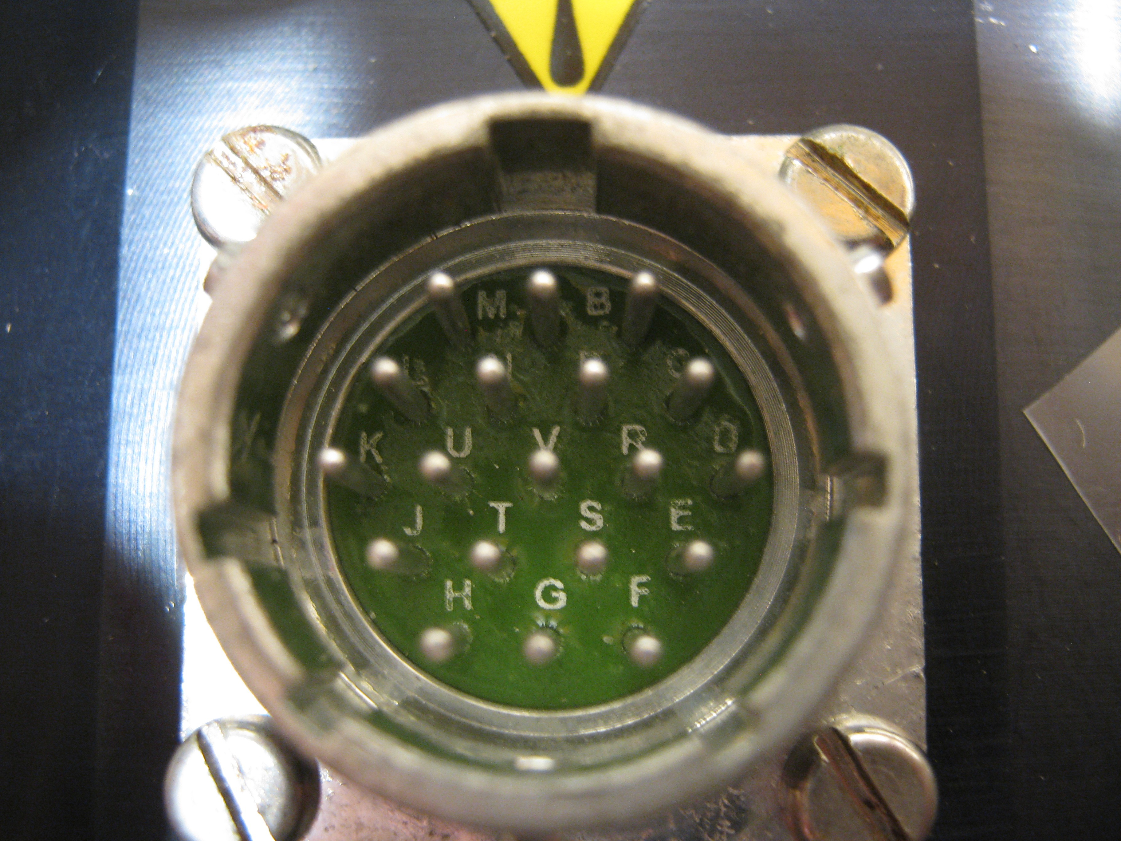
MIL-DTL-26482 compatible, 19 pin male within type 14 shell
Motor Control, and Power Driver
The pump appeared to use a 3-phase BLDC motor, with Hall sensors mounted every 120o. It is unclear what the required bus-voltage is to drive the motor, but phase-to-phase resistance is around 0.7Ω; this certainly indicates a low voltage unit, possibly 12 or 24V. As the rotor starts moving, back EMF will offset applied motive force, dropping drive-current.
In an ideal world, the rotor could be spun up to full speed using an external motor. It would then be possible to ascertain required bus-voltage for the pump, but there are quite a few issues trying to get a unit with a fan-assembly up to 60k RPM in a vacuum.
Given that the unit may be air or water-cooled, it is reasonable to assume full speed power consumption in the region of 200W. Initial tests will be made using a 24V/30A telco power supply, this implies that each leg will require around 3A.
First part of the project is to build a prototype controller. Initial choice of power interface is the Mitsubishi PS21245, since there are several tested units immediately available, along with some associated experience. These units are designed to drive high-power, high-voltage outdoor heat-pump fans, but appear to work OK with supply rails as low as 24V.
4th gen IGBT Inverter Bridge for 3 phase DC-to-AC power conversion
It would be possible to build a more efficient power controller using N-FETs driven by something like the 3 x IR-2104 half-bridges, however this would be a moderate amount of effort, and would dilute the object of this project.
Motor Commutation
BLDC commutation is achieved by using the currently active Hall sensor output to set the context of the drive signals. Since the 3-phase bridge module is an integrated collection of three half H bridge drivers with level shifting, there are six control signals; high-side and low-side drive for each of the phases U, V and W.
Note that HALL values 0 and 7 are illegal.
From the example above is becomes clear that the high side driver inputs for U, V and W only ever need to be a ‘1’ or a ‘0’, so can all GPIO pins. Low side driver inputs for U, V and W appear to able to be always driven by PWM, where the modulator is either set to output 0 (inactive), or to a PWM during the relevant Hall sensor phase.
Torque, and by extension current and speed are set by the associated PWM mark-space ratio.
Commutation State Machine
The safest, and possibly most elegant way to implement the state machine to control BLDC commutation is a hardware solution, so each of the six overlapping HALL input states (from the three HALL inputs) are used to direct the motor-current to the currently selected commutation arm of the motor.
Adjustable (PWM) control current was implemented using an 11-bit counter clocked at 24.576MHz. These 2048 states create a refresh rate of 12kHz, or 83.33us. A synchronous serial data stream for a small microprocessor loads a holding latch that then creates a PWM output from a magnitude comparator that compares the 11-bit counter with the holding latch. This mechanism was implemented using a 128 element CPLD/FPGA, along with a simple double-buffered serial interface. Initially, it was intended to implement a simple frequency counter to measure rotational speed in this same CPLD, but given the (relatively) low frequency of rotation (less than 1kHz) a time-measuring method was later implemented in the attached controller.
Prototype BLDC Test Motor Control
Since this was the authors first attempt at controlling a BLDC motor, (and a very valuable lesson at that), some considerable effort was put into building a prototype controller for a similar class of sensored motor.
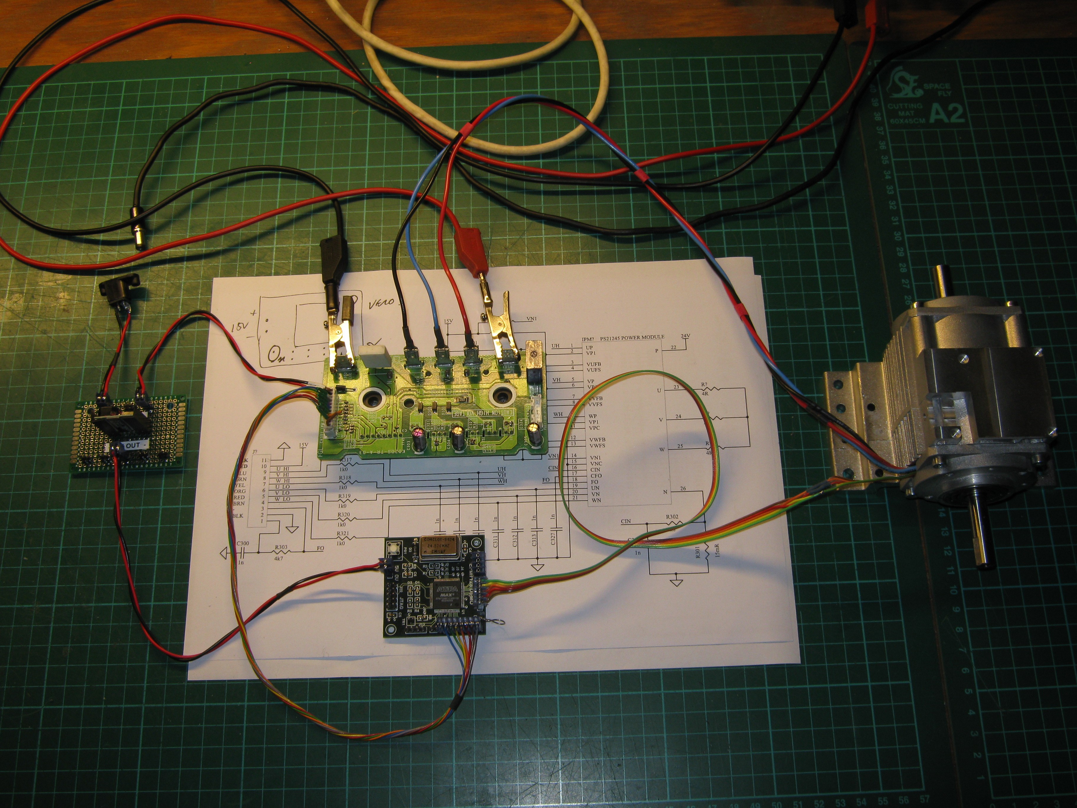
BLDC test platform
In the photograph, with IGBT module above, CPLD/FPGA below, motor to right, and PSU to left. Speed selection was ‘slow’ or ‘fast’ and selected by a button on the CPLD/FPGA board. The selected constants were initially baked into the test firmware.
Getting to this working, early stage of the project was a considerable amount of effort given that the IGBT module was initially in a grubby and untested state. The module also had no documentation, so a full schematic had to be drawn, and various input filter components had to be changed before the module would run at 12kHz. There was also the matter of designing the preliminary commutation state machine in Verilog, and producing accurate documentation associated with hook-up, testing. There was also the matter of photographic records.
The only real mistake during this phase was that the HALL outputs from the small test BLDC motor were not behaving as expected. This motor originated from some medical equipment, so again was acquired without part number, specification or interface details. It was quite an education to disassemble the test motor and discover that previous assumptions about the use of the five instrumentation wires were wrong. After re-assembling the test-motor and updating associated documentation, commutation was established. This test-motor was slightly damaged in this process, but given that it had been acquired only as a test unit, this is of little consequence.
Initial Pump Control
With the test platform working, the real pump was (very) carefully attached and with some huge sign of relief started oscillating to and fro. Rotational commutation was achieved by swapping two main motor wires.
Turbo-pump attached to test platform
It is worth noting that the cable assembly (with the black braid in the photo) took almost six hours to design, document and fabricate. Considerable effort was taken over connector selection (to the controller), motor cable shielding, system grounding, and generally being very aware that a three-phase 24V motor carrying 6 amps switching at 12kHz is likely to be very disruptive to associated electronics. Single point grounding, and separate power supplies for control and power were essential.
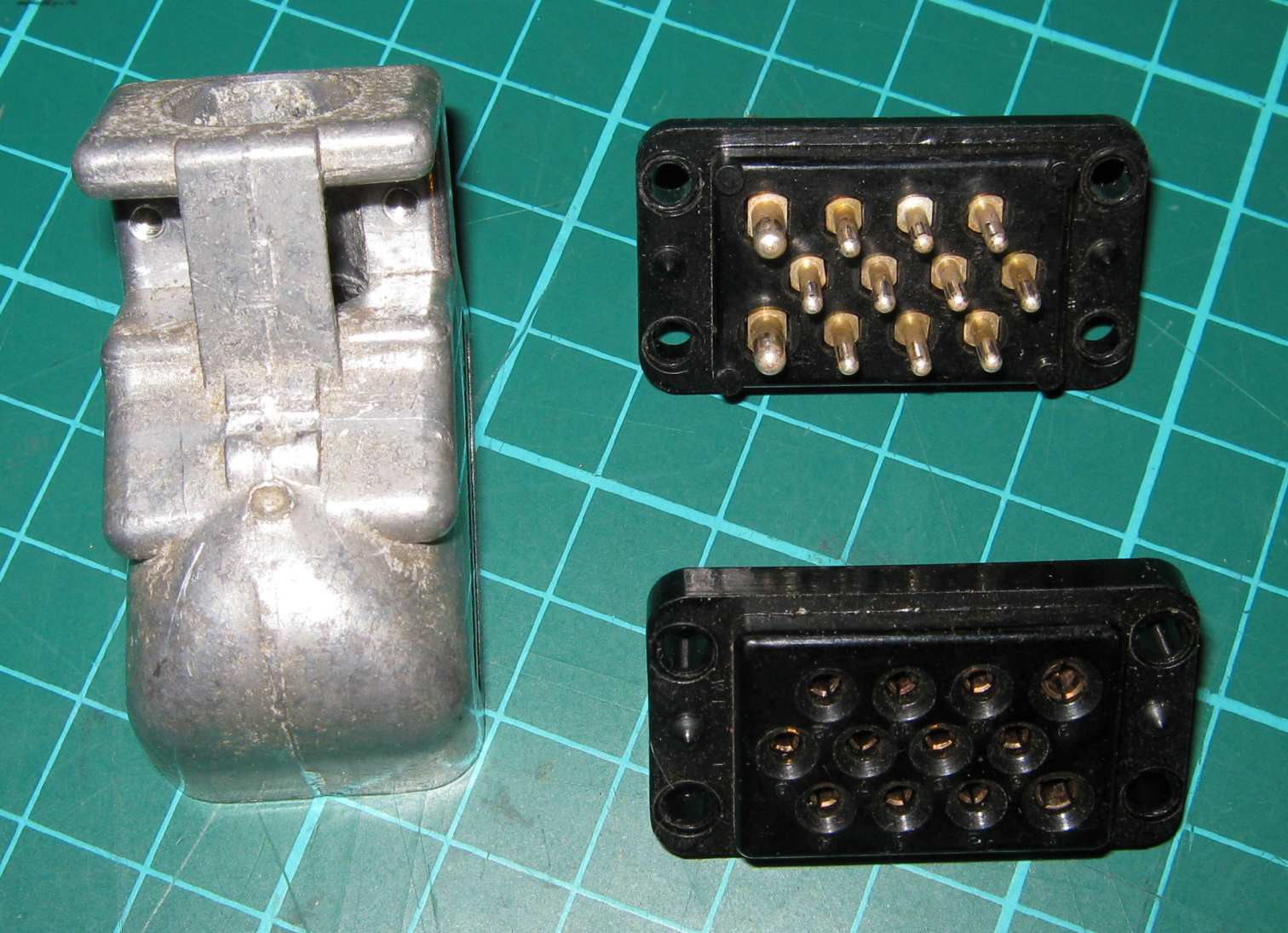
Belling Lee Unitor Pattern 102 connectors
After quite a search, a small pile of rather old connectors were located which were fit for purpose for connecting the motor-cable to the controller. These took quite some effort to clean up, but ended on in a good, clean and usable condition.
In terms of actual wiring, the motor phase-cable shield extends from Neutral of the IGBT module over the extent of the motor wiring. The far end is not connected. Control cable is grounded to chassis at both ends. Motor cable shield, and control cable shield are electrically isolated.

Motor drive screening, and screened Hall sensor cable
The Hall sensors associated with the motor appear to run fine on 5V, and consume a few tens of mA. Each Hall sensor is connected to an FPGA input via a 2k2 pull up, and a 1nF filter capacitor to ground. This forms as a last-gasp filter to catch any remaining noise induced in the sensor lines by changes in current of the main motor drive.
H-Bridge Timing Overlap, and other surprises
An early embarrassment with the commutation engine design was that the issue of H bridge overlap timing was completely forgotten, and overlooked. Briefly, when driving an H bridge, it is rather important to have a guard time where top and bottom drivers are switched off when moving from enabling one, to enabling the other. The consequence of not doing this is that the power supply is momentarily shorted out at each transition. The solution was quite simple. If the next state of the commutation state machine inputs (from the Hall sensors) is different from the current one, then a 2.6us timer is started which holds all H bridge driver inputs at an inactive state for the duration.
A further surprise during development was the realisation that the back-EMF from the BLDC motor was feeding back into the 24V SMPSU, and causing it’s control loop to become unstable every time the motor commutated. The fix was simple enough – a reasonably grunty TO-220 Schottky rectifier between the power supply and the IGBT power input, and a couple of 2200uF capacitors across the IGBT main bus, to further absorb any back-EMF.
So, after a considerable amount of work, we seem to have done a reasonable amount of due-diligence on the condition of the pumps, IGBT power driver, and appear to have a reasonably good handle on the state machine required to handle commutation, with a preliminary design written in Verilog.
Mechanical Packaging
The project was now taking on sufficient complexity that some effort was required to provide some mechanical integrity of all of the modules, power supplies, and connectors. This process step is going to happen at some point in the project, and by tackling it early, the chance of loose modules, and loose wires causing damage can be minimised.
An old 19” aluminium rack case was located, and cleaned of existing electronics. The plan was to overlay front and rear panels with laser-cut 3mm white Perspex. This plastic overlay will have been cut with required apertures to allow all controls and connectors to be presented neatly, and the base was cut out of 3mm MDF.
Before the mechanical aspect of the project could be worked on, a strong and complete electrical design had to be completed, to ensure that all mechanical aspects of the project were fully understood. Appendix A outlines the initial feature set, along with some implementation notes.
The initial mechanical placement of boards resulted with the IGBT module sitting on MDF. This was quite a thermally-optimistic decision, but provided the simplest solution with minimal mechanical coupling of the assemblies.
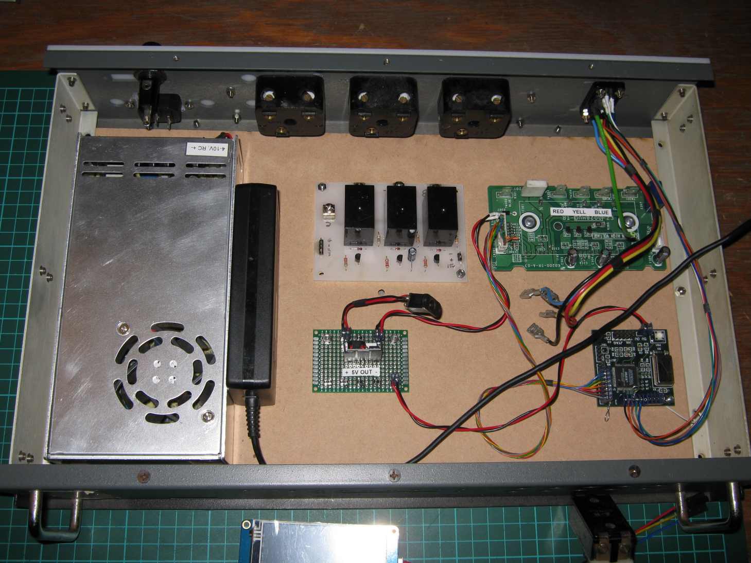
Early stages of packaging the controller
After a few higher-power test runs, this decision soon was overthrown and the power module moved to the bottom of the aluminium case. Unit heating dropped dramatically once attached to the aluminium sheet base (once the paint had been removed).
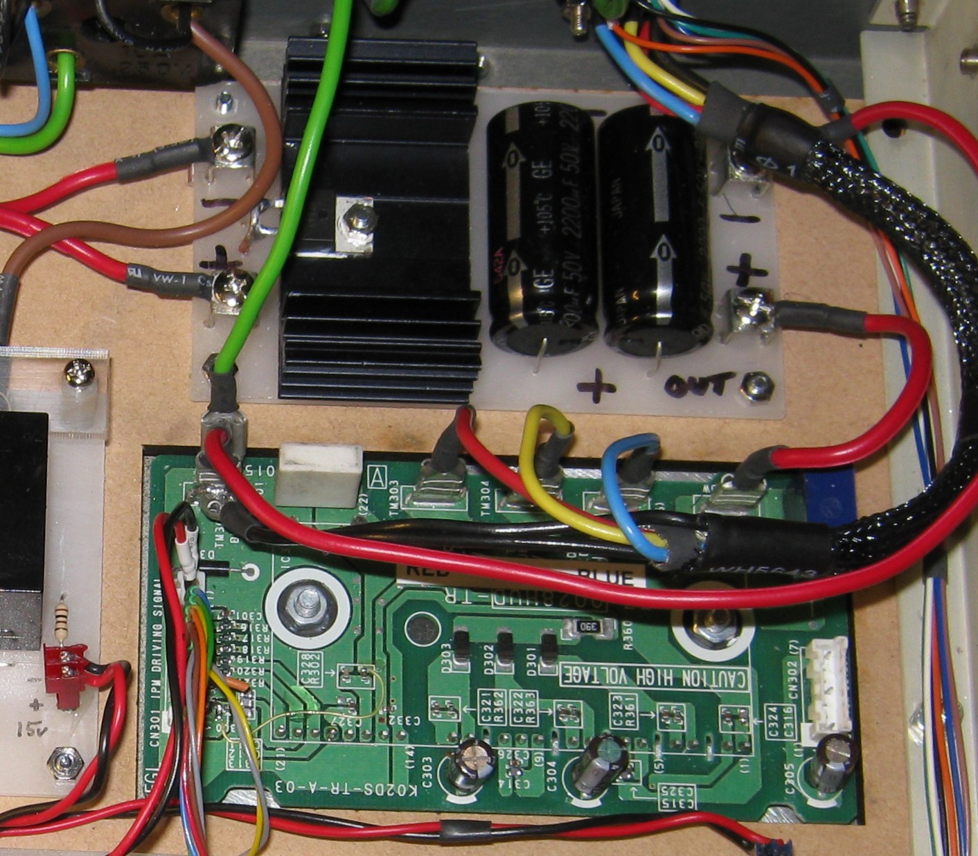
Final resting place of IGBT power module, and PSU filter
Main Processor
Given the overall complexity of the project, it was a given that a microprocessor would be required to manage the system. Duties include managing the User Interface, control of mains relays, and last but not least, interface to the small FPGA, which is managing main-motor commutation. A front panel USB connector would be provided to assist with firmware development (debug), firmware updates via a bootloader, and LCD configuration updates. An Arduino Nano module was readily available, but the associated processor (ATmega328P) only had a single serial interface. This part was replaced with an ATmega328PB (having two serial ports). A new bootloader was modified to add LCD passthrough mode, and programmed into the factory-fresh part.
This small step of upgrading the processor, and associated bootloader was quite an adventure in itself. The Atmel ATmega328P was the initial core CPU used by the incredibly popular Arduino series of boards. There is a massive online community supporting the part, and an associated mature, open-source toolchain. The B part introduces lots of useful, new peripherals, including a second serial (USART) and has a following of approximately zero people, ±3dB1
It didn’t seem like an unreasonable assumption that Atmel (the manufacturer of the CPU) would have the latest tool-chain associated with this new (2015 vintage) part supported, but this assumption was completely wrong. After quite some effort, the required tools were located as part of the Arduino development suite. It was a reasonable simple step to remove all required binaries from this suite and to package a stand-alone toolchain (I use a small make-file instead of the Arduino IDE). This allowed me to remove the one morally-reprehensible fix I was forced to implement allowing the old tool-chain to produce compatible code for the newer part.
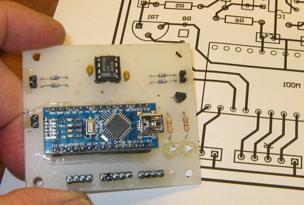
Arudino Nano with ATmega328PB processor module mounted on processor main board
As presented, the original processor is programmed with the Arduino bootloader. This code checks for specific character sequence on USART0 after the CPU has been is reset. If none are detected within a timeout period, the main application is executed.
Touchscreen LCD, and the Bootloader
The bootloader as supplied by the Arduino toolchain is fine for loading new code into the main CPU, but a mechanism was also required allowing the attached LCD (on USART1) to be loaded with new configuration code. For various reasons, the bootloader is the correct place architecturally to implement such a feature.
The user interface is implemented using a programmable colour touch screen module manufactured by Nextion. This unit uses a serial interface for normal operation, as well as for programming, along with a 5V supply. For LCD configuration updates, the Nextion editor (running on a PC) sends a specific escape sequence to the LCD allowing updates.
To allow the CPU to control pump-speed, there is a simple synchronous data link between CPU and FPGA boards, and one of these pins was tied to the push button on the FPGA board. The new bootloader was modified to check if this push button is held down at reset time. If so, the modified code enters LCD boot mode, where USART0 (on the USB channel) and USART1 (LCD) are cross-linked.

LCD editor upload screen
At that point, the USB port (and by extension the LCD editor) can talk to the LCD directly.
LCD screen layout in editor
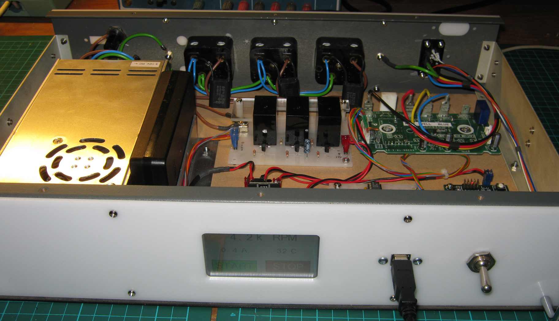
Front Panel, showing LCD, and USB ports
To upload a new LCD configuration from the Nextion editor into the LCD, all that is required is to ensure that the correct COM port on the PC has been selected, and that the button on the FPGA button is held down for a moment when the GO button is hit on the editor.
The CPLD/FPGA Commutation Engine
Many years ago, I designed a small FPGA board, using a 128LE CPLD device. The unit runs on 5V, and can be configured and programmed using Verilog, with the aid of the Quartus II development environment. This was ideal for the relatively simple task of implementing a BLDC commutation state machine. Earlier text describes required waveforms to drive the pump, along with associated Hall sensor states.

BLDC commutation engine, based on a CPLD board
Rear panel, Relay Board and Mains Power
It was decided that the next step was to mount all of the fully understood, and awkward features to the case. These included the main 24V power supply, pump connector, output mains sockets, and relay board, as well as mains input, and fuse.
The three mains sockets are associated with providing power to the roughing-pump, the 24V internal power supply and associated mains cooling fan for the turbo-pump, and a vacuum-vent solenoid.
Control of these power sockets was by way of mechanical relays, being engaged using traditional bipolar transistors. Relay current is in the order of 50mA at 10V, while the transistors require a few hundred microamps to engage the relays due to their very high Hfe. A 10k base resistor was adequate to allow the processor to control these relays. Each relay contact also had a snubber network in parallel, in an attempt to extend contact life.
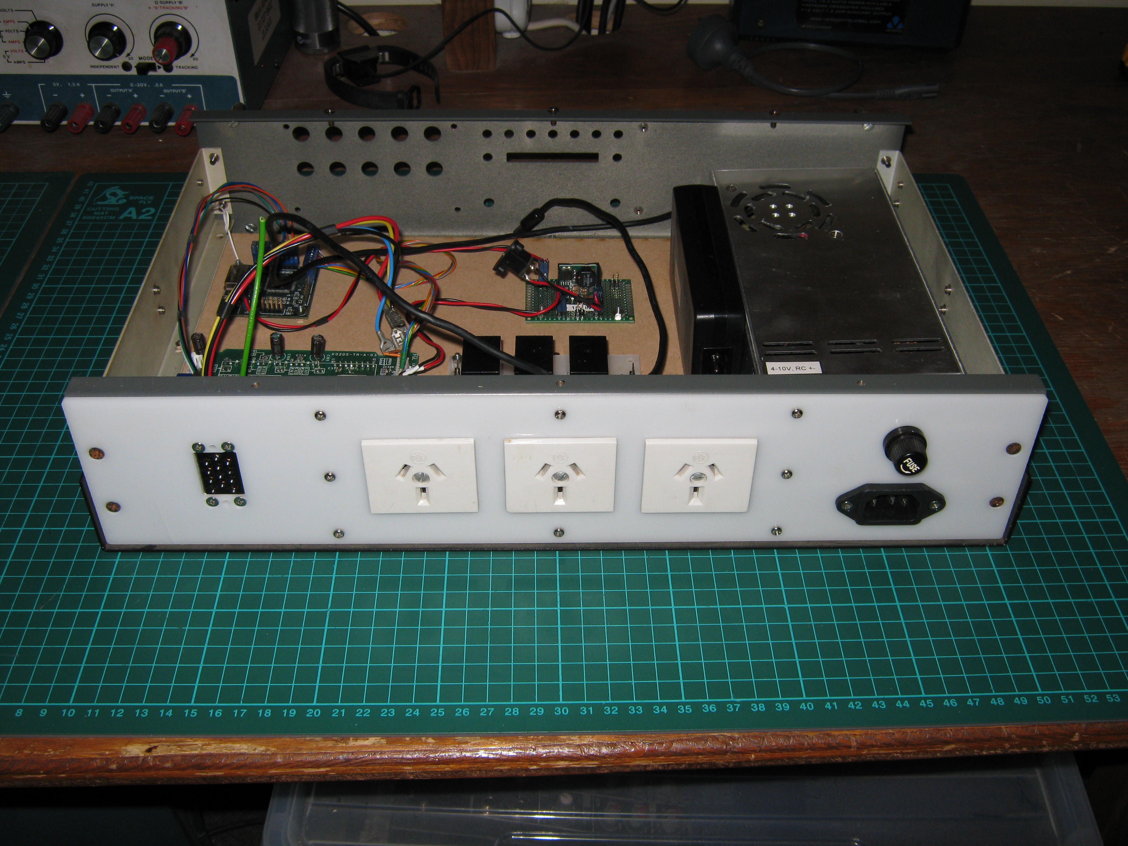
Relay controlled mains outlets
The idea of using Solid State Relays for this control application was considered, but mains rated, 15 Amp, mechanical relays were readily available, smaller, and a more robust solution.
Main Application
System firmware has been written in C, and compiled using the AVG-GCC V 7.3.0 toolchain. Application build, and upload is via a suitable Makefile, along with GNU Make V3.81.
As of this writing, the main application is a very simple collection of sequentially executed small tasks which are each run before a 500ms delay is encountered, then the process repeats. If the system is started (from stop), mains is applied to the 24V internal PSU, and PWM controlling motor speed is slowly increased over 50 steps until some maximum value is reached. If the system is stopped (from run), the motor PWM is slowly decreased until it reaches zero, then the 24V power relay is disengaged. Every loop (every 500ms) the LCD is updated, and any incoming commands from the touch-screen are processed as required.
If a terminal is attached to the unit, and a single character is sent to the main application, the system will drop into a Command Line debug mode, where individual elements of the hardware can be exercised.
Motor speed is measured by way of one of the HALL inputs causing a pin change interrupt. This in turn is used to measure and reset a 16-bit hardware counter that is being incremented by TIMER1. This hardware counters is being clocked at 2MHz. If the counter overflows (motor not rotating, or too slowly to present a useful result) the U16 variable used to communicate rotation time to the main app is set to 0xFFFF. This mechanism allows motor speed measurement down to about 1000RPM. Scaling is by a floating-point divide, which is a slow process, but given the 500ms delay in the main loop, is of no consequence to system performance.
Analogue Inputs
The system has two analogue input worthy of monitoring, spindle current, and motor temperature.
Spindle current is the sum of the return (ground currents) from the three low-side IGBTs, passing through a 15mΩ resistor. This will drop 75mV assuming a full speed spindle current of 5A. This voltage is differentially monitored by an amplifier with a gain of 34, and whose input common-mode range exceeds power rails by ±0.3V. Using the ADC on the main-processor with a 5V ADC reference, this yields an input range of just over half-scale with respect to 0V. It is worth noting that that when the motor is being driven at less than 100%, this is the average of the PWM excitation current.
Motor temperature is monitored using a 5V rail referenced thermistor (nominally 100Ω) that is excited by a 1mA current sink. Amplifier topology is very similar to the spindle current except the output is referenced with respect to full scale of the ADC. It is unclear how the 100uW thermistor dissipation (because of the constant current) affects performance of this circuit. One obvious way to reduce interaction would be to only enable the current sink when measurements are to be made, reduce sink current, and increase amplifier gain.
Custom Wiring Boards
Several custom boards were required for this project including a motherboard for the Arduino Nano processor, a Relay board, and a power conditioning board. Each board was designed using the usual process of schematic entry and PCB layout using Protel 99SE. Special attention was paid to the layout, so it could be fabricated as a single layer design.
The associated Excellon drill file, and Gerber keep-out layers were then processed by some home-written software ‘P2D_14.exe’ to generate a DXF file. This file was then used by the laser cutter to cut a 2mm plastic sheet into a ‘bare-board’. Copper ‘tracks’ were then added by hand, guided by a print of a mirror image of the PCB layout file.
Resulting DXF (top view) of the processor board
CPU board (bottom view), hand wired on 2mm laser-cut plastic sheet
System Performance
The pump is designed to start operation in a near-vacuum which is not convenient for bench testing. However there should be no adverse effects by spinning the pump at atmospheric pressure as long as an eye is kept on unit temperature.
At atmospheric pressure, initial tests using a 24V/8A power supply managed to get the unit to spin up to 7300rpm, while consuming around 7A. Not surprisingly, the unit started to warm up after a few minutes.
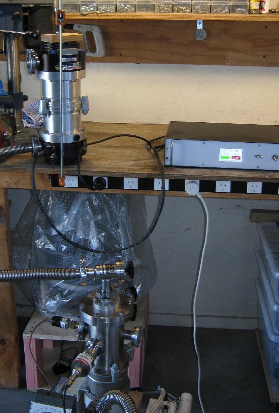
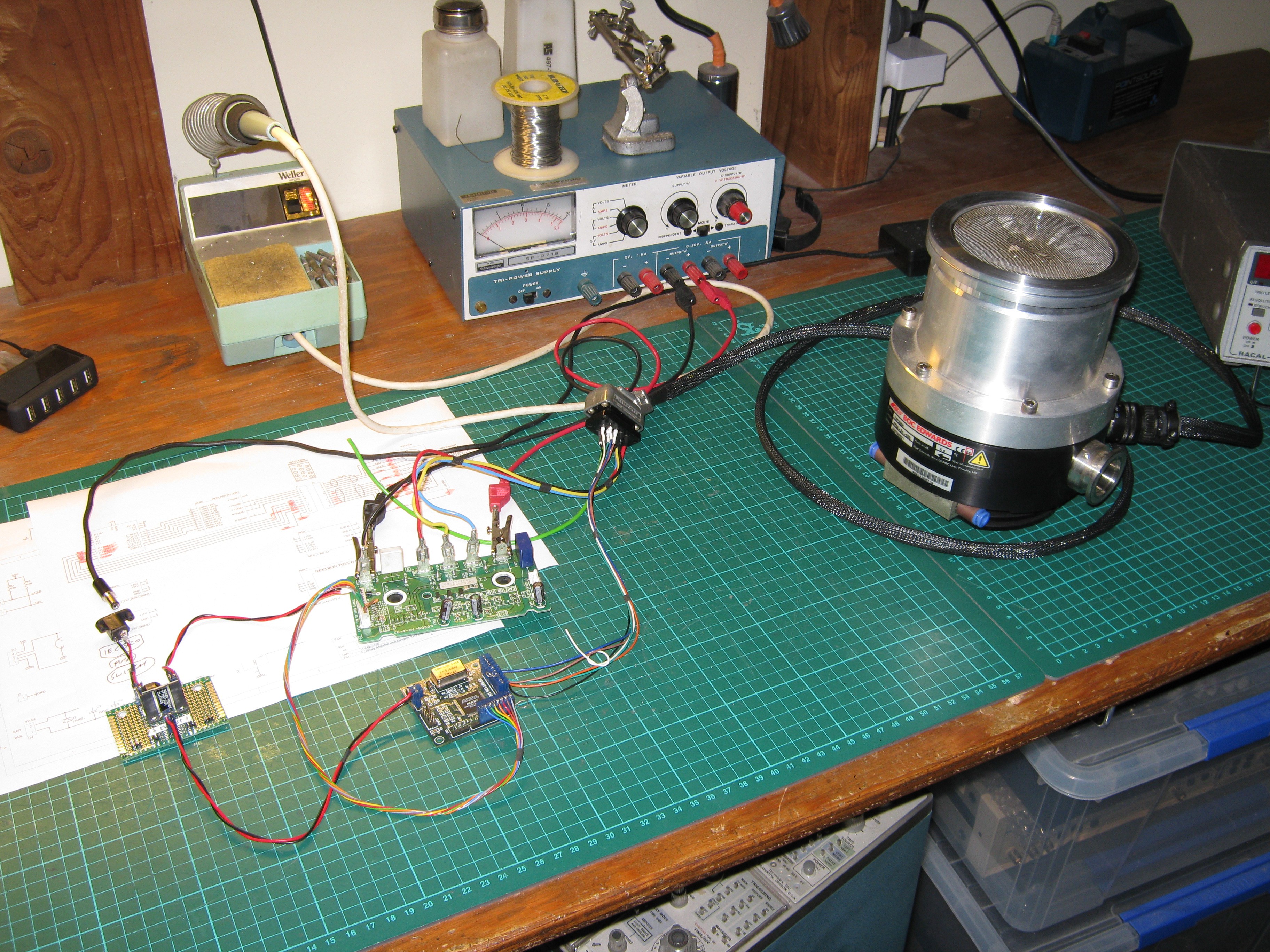
Vacuum testing of the pump and controller
By bolting a second Turbo-pump on top of the unit being tested, blocking the CF-25 of the second unit, then pulling down the whole system to 1x10⁻⁵ Torr it was possible to evaluate the pump in a much more realistic environment. This set of tests resulted in almost 20k RPM spindle speed, with the unit consuming 0.6A in its steady state.
Clearly the pump is not designed to run on 24V, so the vacuum tests need to be re-run using a 48V supply, and with a much gentler acceleration ramp (or current limited) being applied to the pumps windings.
Final notes
The system underwent around two complete revisions during this build, and despite this being a prototype project, much was learned. More work needs to be done to complete the project, the first item is to get the pump up to around the 60k RPM target. There as also some (hopefully) straightforward issues around relay sequencing that need resolution.
This project was undertaken between 26 March 2020, and 1st May 2020, during the COVID-19 lockdown within New Zealand, so solutions can be pragmatic at times,
With thanks to Warren Petigrew for reviewing this document.
Mark Atherton
19 June 2020
New Zealand.
References.
1) Old professional audio design joke. Please indulge the author.
This article is published under the Creative Commons Attribution License (cc-by). Re-distribution and re-use of this work is on the condition that the creator (Mark Atherton, New Zealand) is appropriately credited.
Appendix A, Initial specification
Front panel
Touch LCD
Mains switch
USB-B socket
Internal
Processor board
Host board, ATmega328PB
-ADC amplifiers
-IGBT current sense
-Motor temp thermistor
-Thermistor current source
-Tacho input from Hall sensor
IGBT board
Reworked assembly from an HVAC system
Cleaned and tested
Commutation engine
CPLD/FPGA board
Relay PCB
Rear panel mains sockets
15V, 1A PSU
IGBT low-side
Relay board
5V regulator
5V, 1A regulator
Processor board
CPLD/FPGA board
LCD touchscreen
24V, 8A PSU
Main pump power
Single point grounding
Rear panel
Pump connector, 12 pin
IEC320 power in
Power Fuse, 1¼”, 5A slow
AS/NZS 3112 power outputs
-Roughing pump out
-Fan out
-Vent out
Enclosure
19” metal enclosure
5mm MDF internal chassis
3mm white perspex front and rear panels
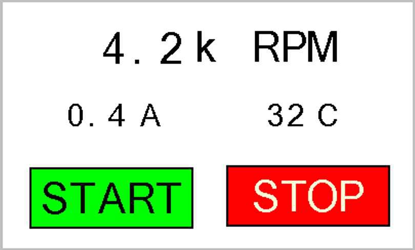
User Interface features
-Start/Stop/Freewheel
-Spindle speed
-Motor spindle current
-Motor temperature
Processor board
ATmega328PB
-USART 0, via USB-bridge
-USART 1, LCD
-ADC 1, spindle current
-ADC 2, motor temperature
-GPIO1, roughing pump relay
-GPIO2, 24VPSU & vent relay
-GPIO3, fan relay
-SPI out, spindle speed request
USB
-CPU Bootloader
-LCD configuration
-CLI debug
Pump connector, 12 way
-Motor, 3 pins
-Motor cable shield, 1 pin
-Hall sensors, 3 pins
-Hall power, 2 pins
-Motor temp, 1 pin
-Control cable shield, 1 pin