 lion mclionhead
It was finally time to build a new remote control for better water resistance. Sadly, the original Si4421 radios were discontinued & problems with the RFX1010 burned the last 2 of those chips. It was never figured out why those failed after working in 2 boards. The Si4463 promised to make enough power to not need a front end & has a higher bandwidth.
The Si4463 is 10 years old but already a beast. It requires all 4 SPI pins. It uses the MISO pin for flow control. While the datasheets show the pinout & an example schematic, they don't have any inductor values.
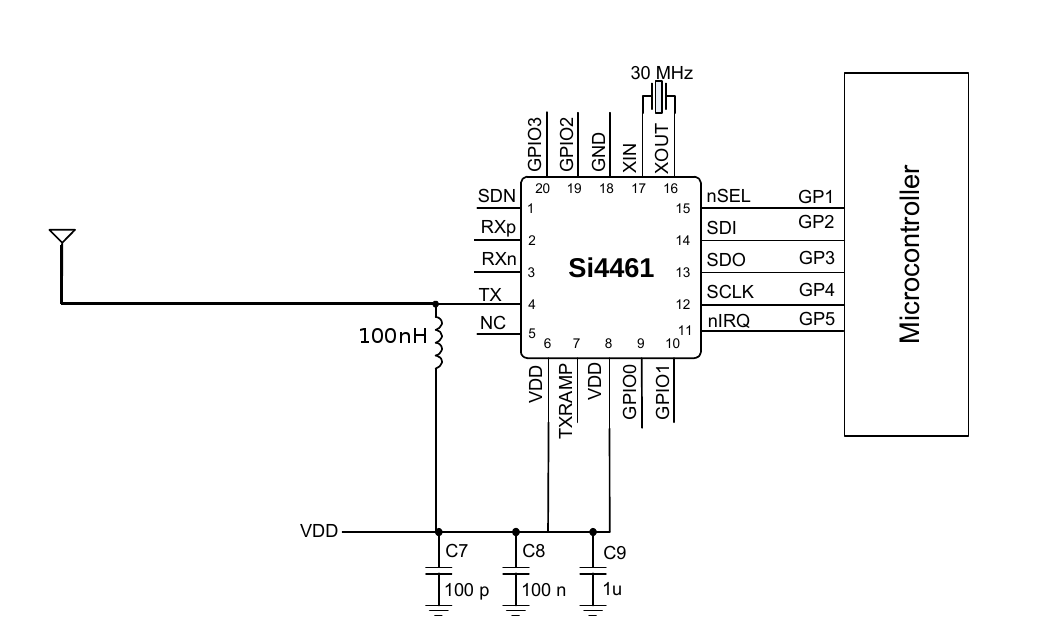
The new dance is separate RX & TX antenna pins. For transmitting, a simple 100nH seemed to do the job. There's no plan to use it for receiving.
The register descriptions in the datasheets seem to be obsolete. All the register values are documented by the Wireless Development Suite (WDS3). Bringing it up is not possible from the datasheets. The WDS3 has a radio configuration application which generates all the required code.
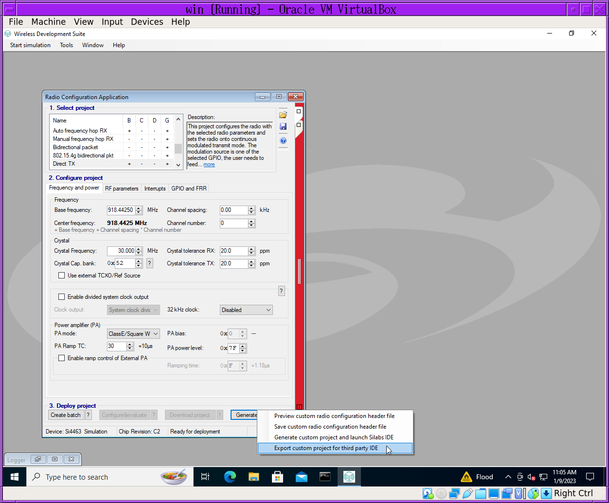
You have to export a custom project after setting all the configuration bits. The header file option doesn't work. The 2 key files it generates are
src/drivers/radio/Si446x/si446x_patch.h
src/application/radio_config.h
The key object is the RADIO_CONFIGURATION_DATA_ARRAY. It's just an array of packets to send to MOSI with flow control codes. The 1st byte is a packet size. Then you send the packet. Then you poll the CTS register before reading the next packet.
SPI is MSB 1st. The datasheet didn't say that. The flow control procedure is in the radio_comm_SendCmdGetResp function. Part of the auto generated array is a firmware patch which requires 512 bytes.
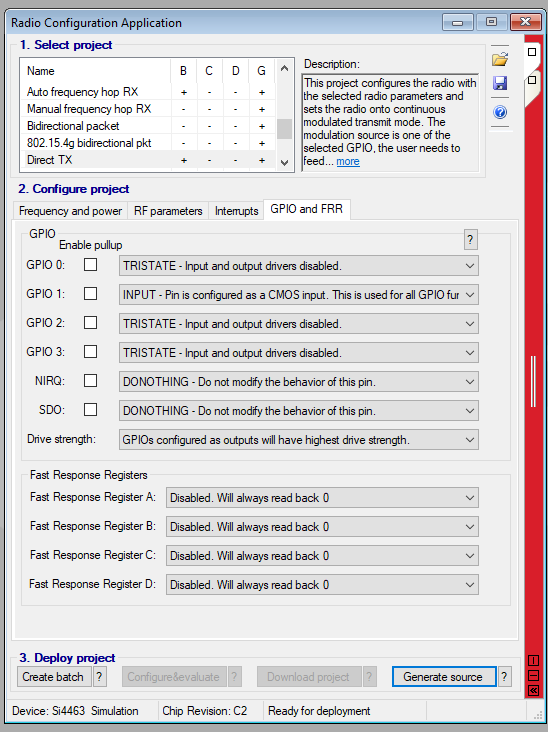
The only requirement for using a UART to modulate the signal is declaring 1 of the GPIOs as an input & selecting Direct TX as the project. Set the other GPIOS to TRISTATE & they can be connected to ground. Then send a START_TX with 0 for all the arguments. That is auto generated in the si446x_start_tx function.
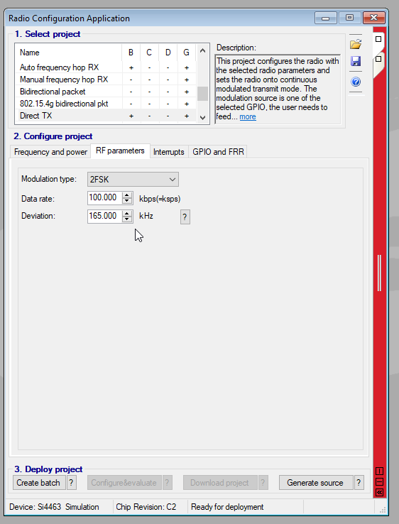
The other trick is setting the deviation to match the Si4421. That's how far the carrier shifts above & below the center frequency for modulation.
For frequency hopping, the channel is sent in the START_TX command, but this is only accurate to 30Hz. The base frequency is accurate to 1Hz. The base frequency is set by the RF_FREQ_CONTROL_INTE_8 & RF_MODEM_AFC_LIMITER_1_3 registers. The channel spacing on the Si4463 is only accurate to 30Hz while on the Si4421 it was within 10hz. To save power, use the channel number in the START_TX command.
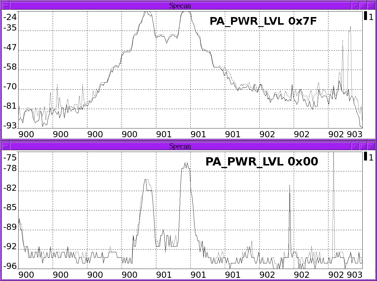
The PA power level is 0x7f for full power & 0 for lowest power.
There is a desire to resend the packet multiple times per hop, but this requires a receiver change. Without a unique ID in each resend, it seems to screw up the hop timing.
The ramp up time for transmitting is under 1ms on the Si4463, which greatly reduces the amount of current required from the 5ms required by the Si4421.
Going into standby mode
The mane thing is all the GPIOs have to be configured as TRISTATE or INPUT. If it's driving the GPIOs, it sucks 10mA in standby mode. Then you're going to put it into standby mode when not transmitting. Poll CTS 1st, then issue the CHANGE_STATE command for standby/sleep mode. Polling CTS after the command might wake it back up. This drops the current to 0 when not transmitting.
Of course, the typical usage involves long delays between state changes, so you shouldn't need to poll CTS at all.
Startup difficulties
The mane reason it won't start up is the ramp time for Vdd being too high. The easiest solution is to connect SDN & drive it high until Vdd is done. Thus, it takes 5 digital signals to start up.
Discussions
Become a Hackaday.io Member
Create an account to leave a comment. Already have an account? Log In.