 Max.K
Max.K How it works:
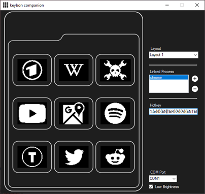
- In Standalone mode, Keybon acts as a simple HID keyboard and shows its preconfigured buttons functions.
- The companion software for windows allows you to create your own keyboard layouts and assign them to any application on your PC. The companion software monitors the applications in focus and changes the layouts accordingly. In this mode Keybon communicates over a virtual COM port. Layouts are sent to the device on demand which in turn sends key events back to the computer.


 Guy Dupont
 Richard
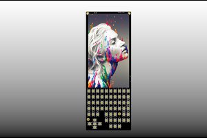
 pcadic
 Alistair MacDonald
Has anybody built one of these recently and found a source for the OLED displays? They're out of stock or back ordered permanently everywhere I can find them.