 Mark Howe
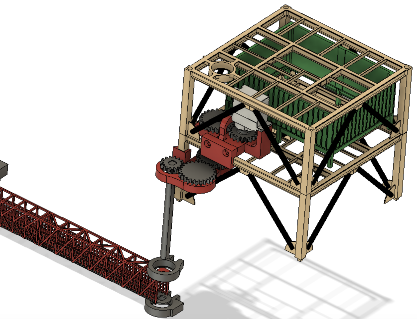
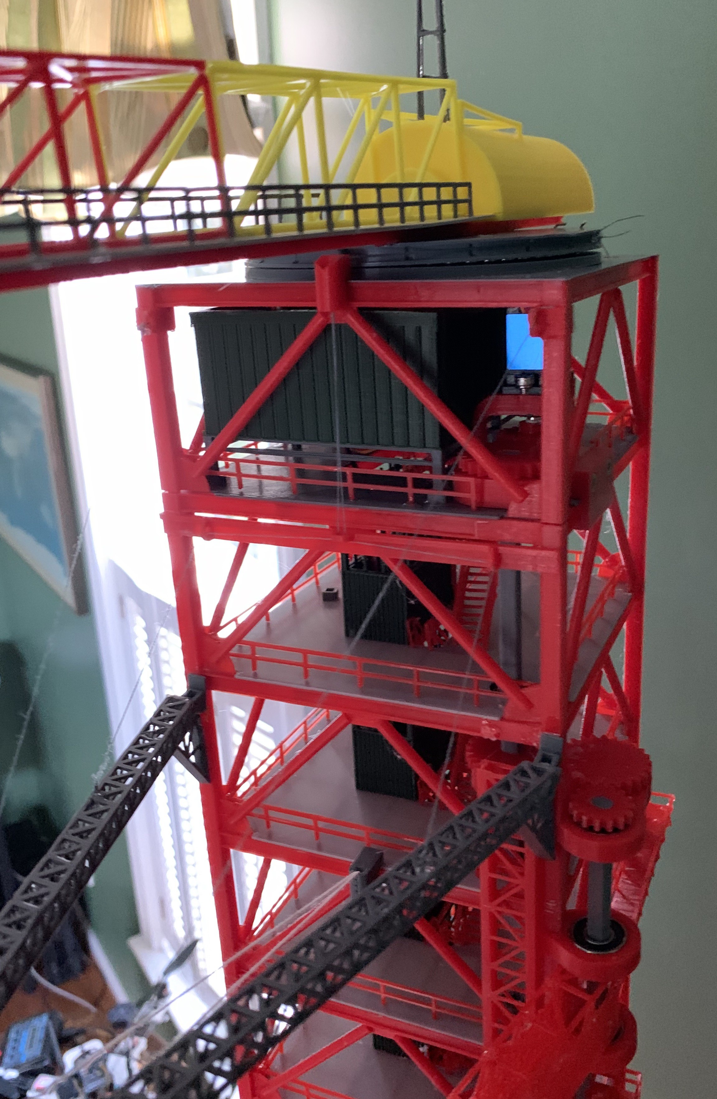
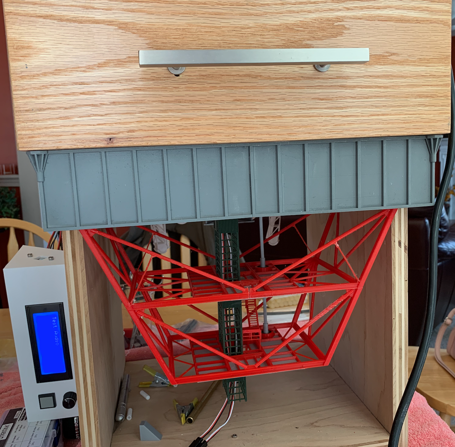
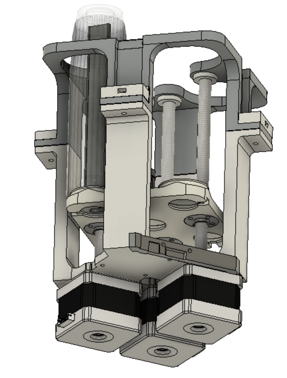
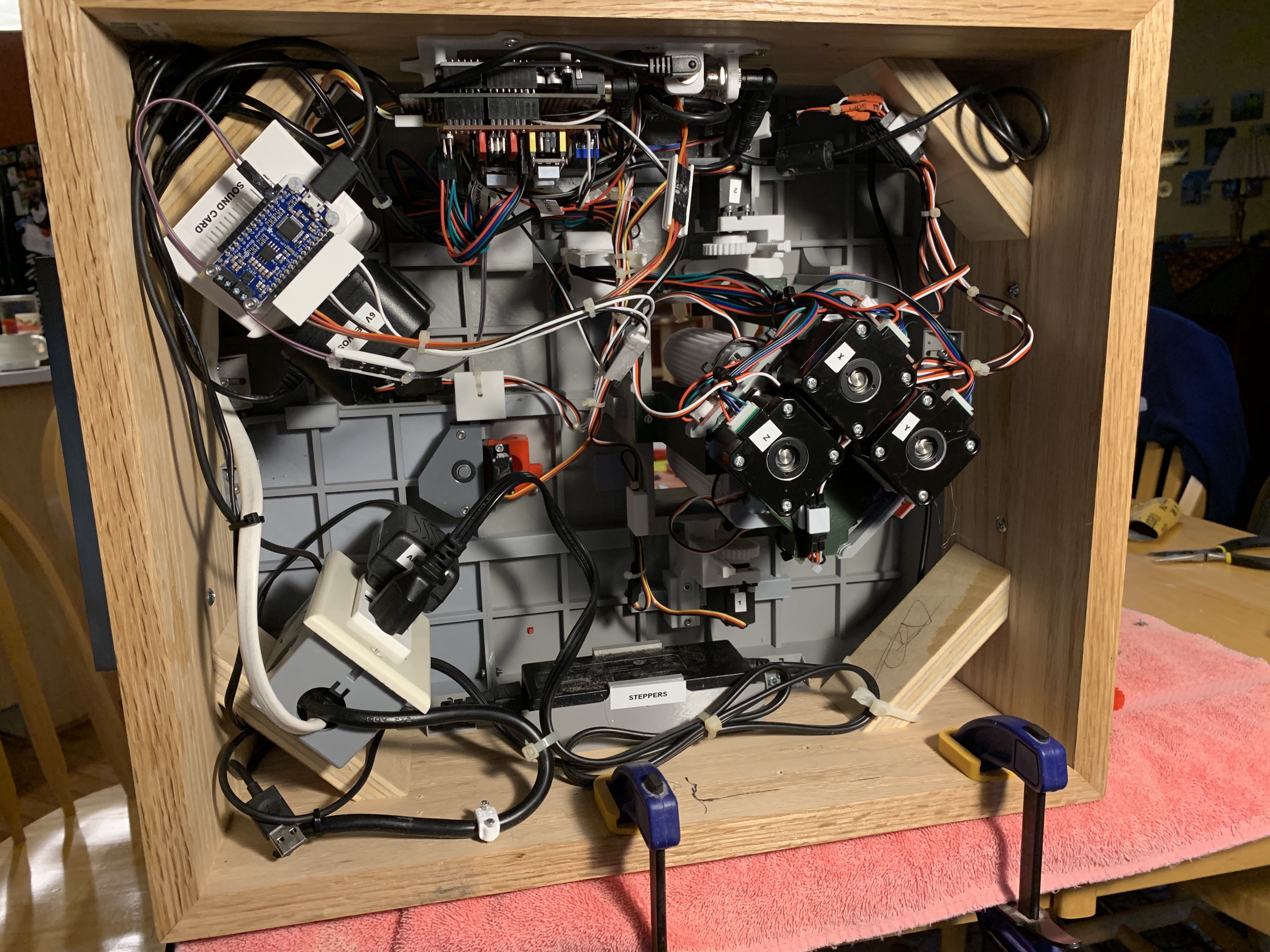
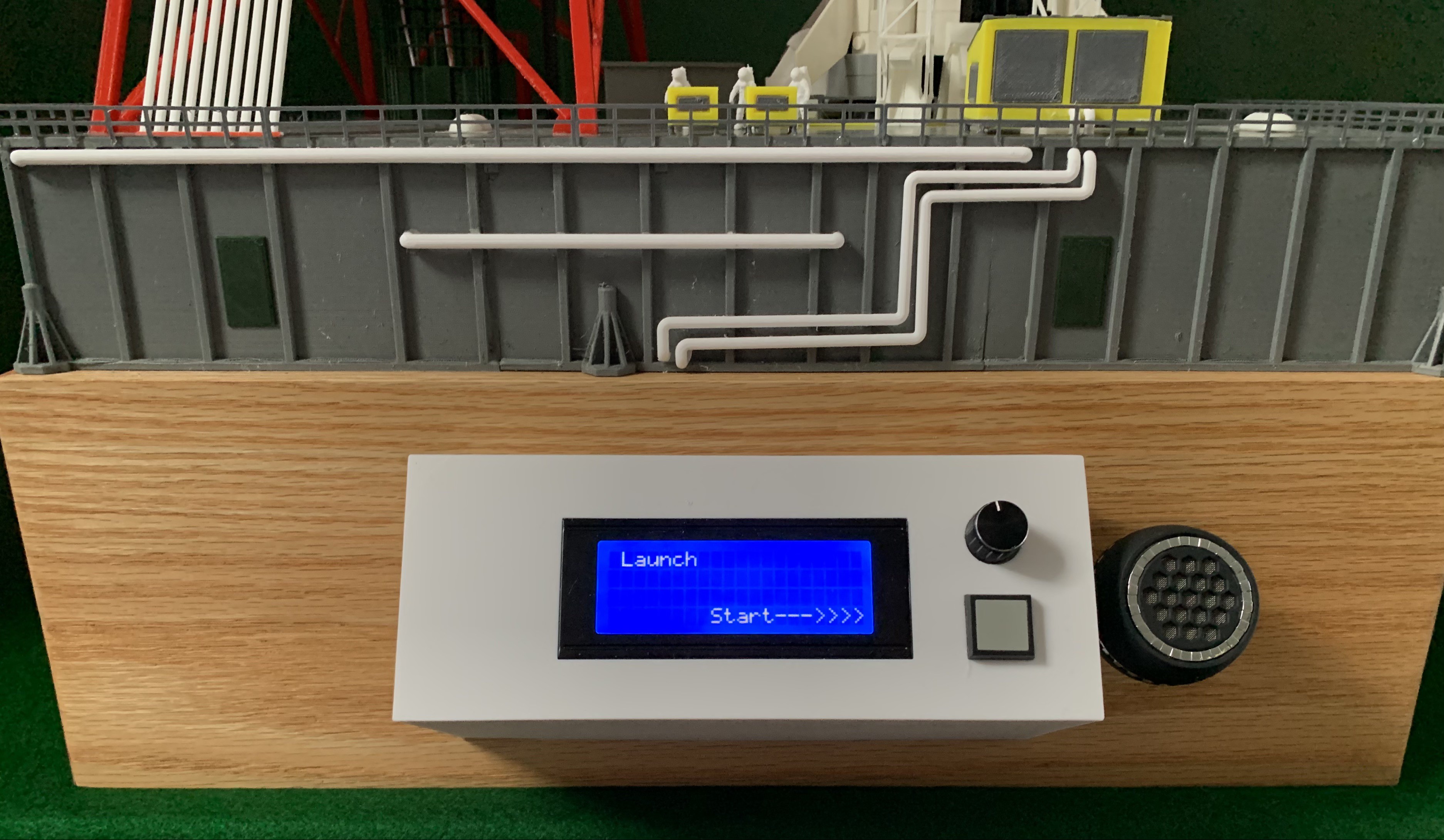
This movie illustrates the launch sequence of the model. After pushing the launch button, the crew arm swings back, pulling up the sway arm on threads. Next the crew walkway retracts. At T-8 seconds Neopixels light up the F5 engine plume tubes. At T-0 the gantry arms swing back, the service arms at the base lift up, and the entire model lifts up about four inches. All controlled by a finite state machine in an Arduino. After a few seconds everything resets back to the orginal positions.
0%
0%
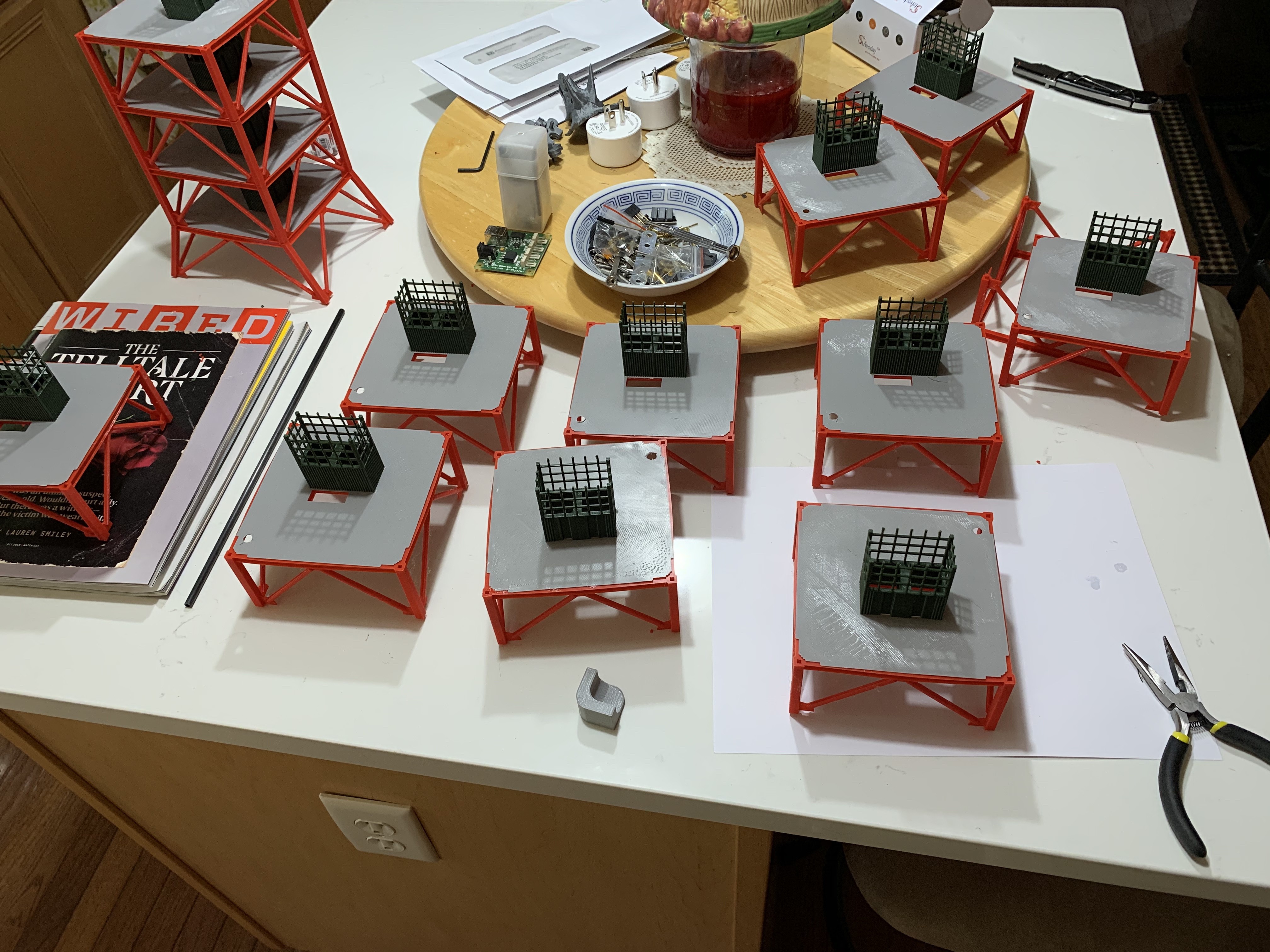
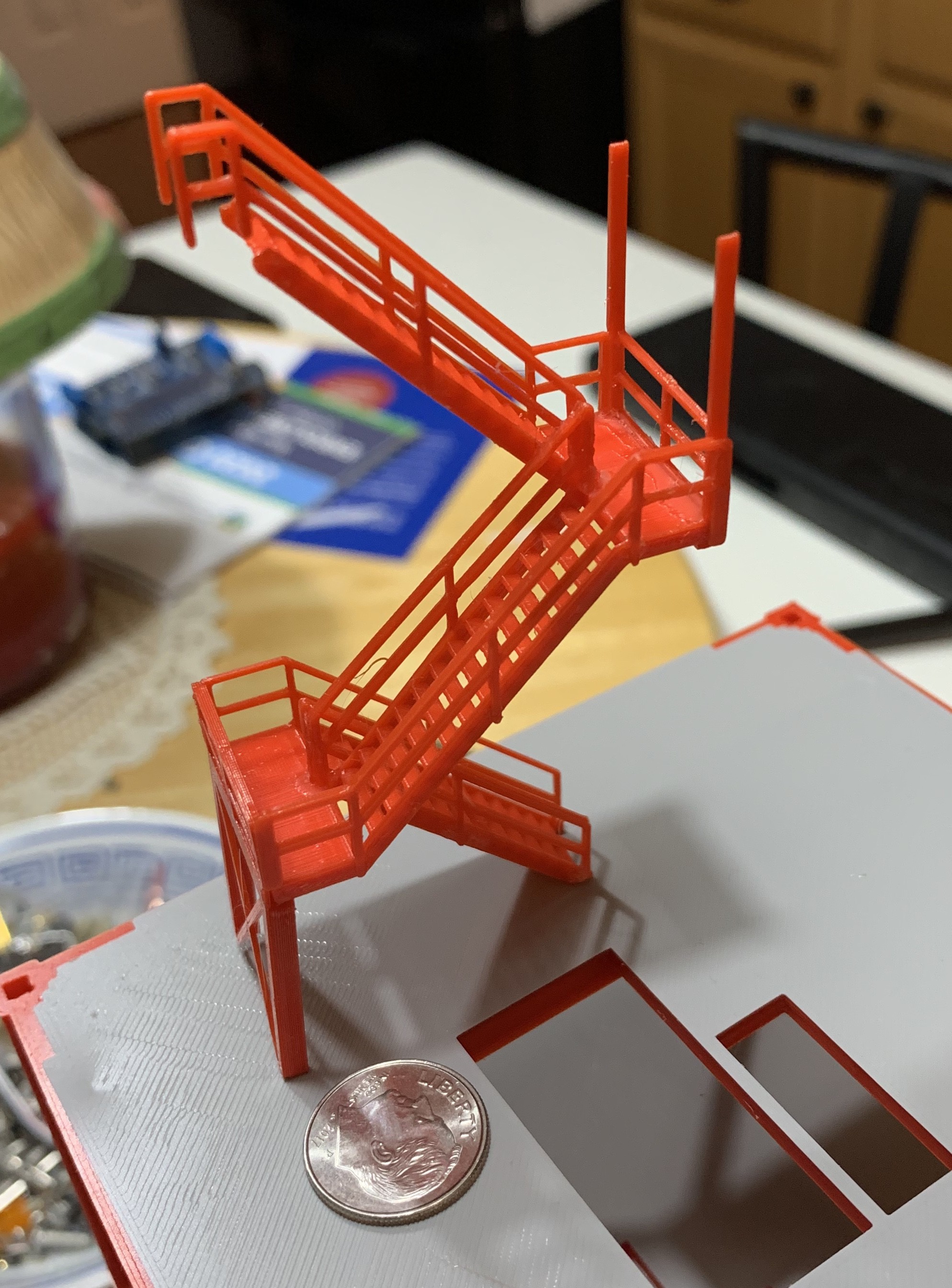
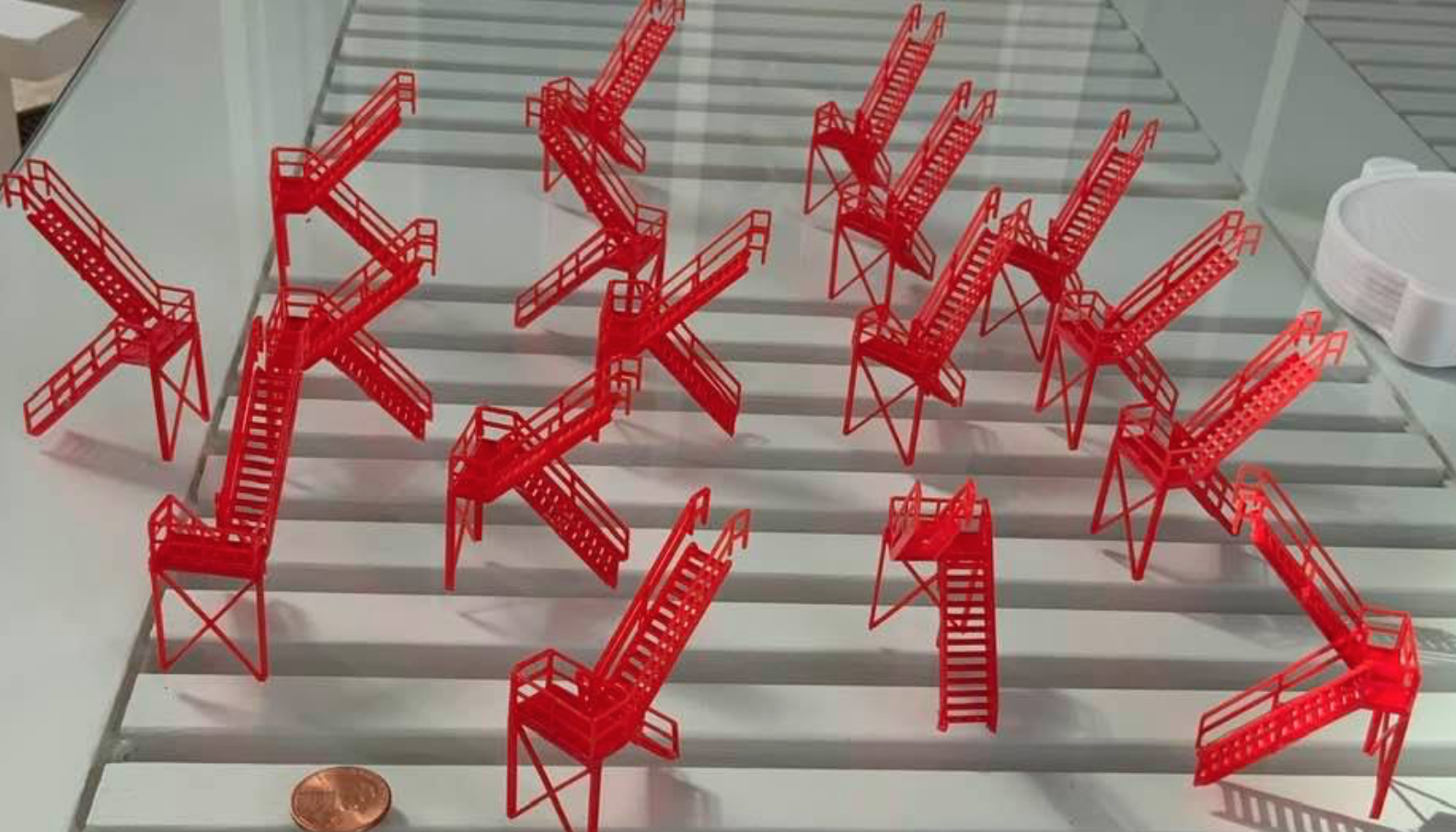
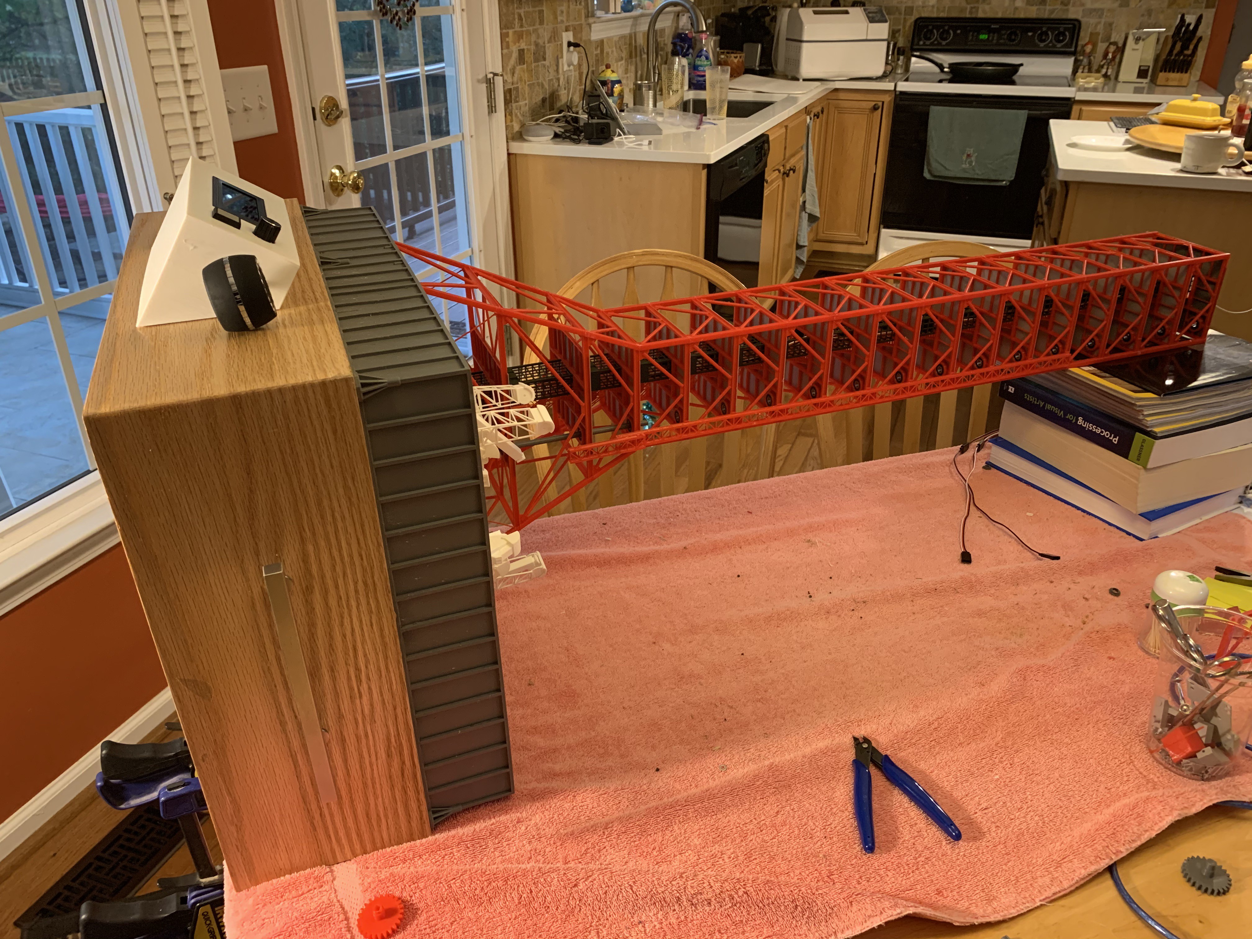
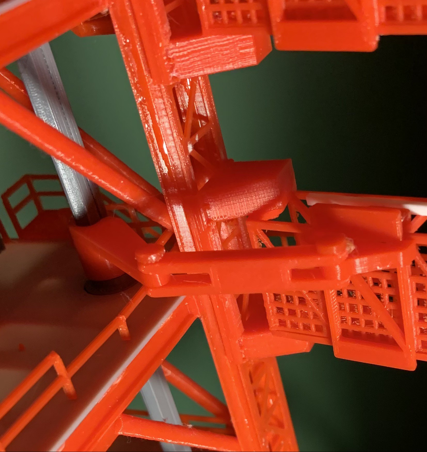
An animated Saturn V launch pad and gantry
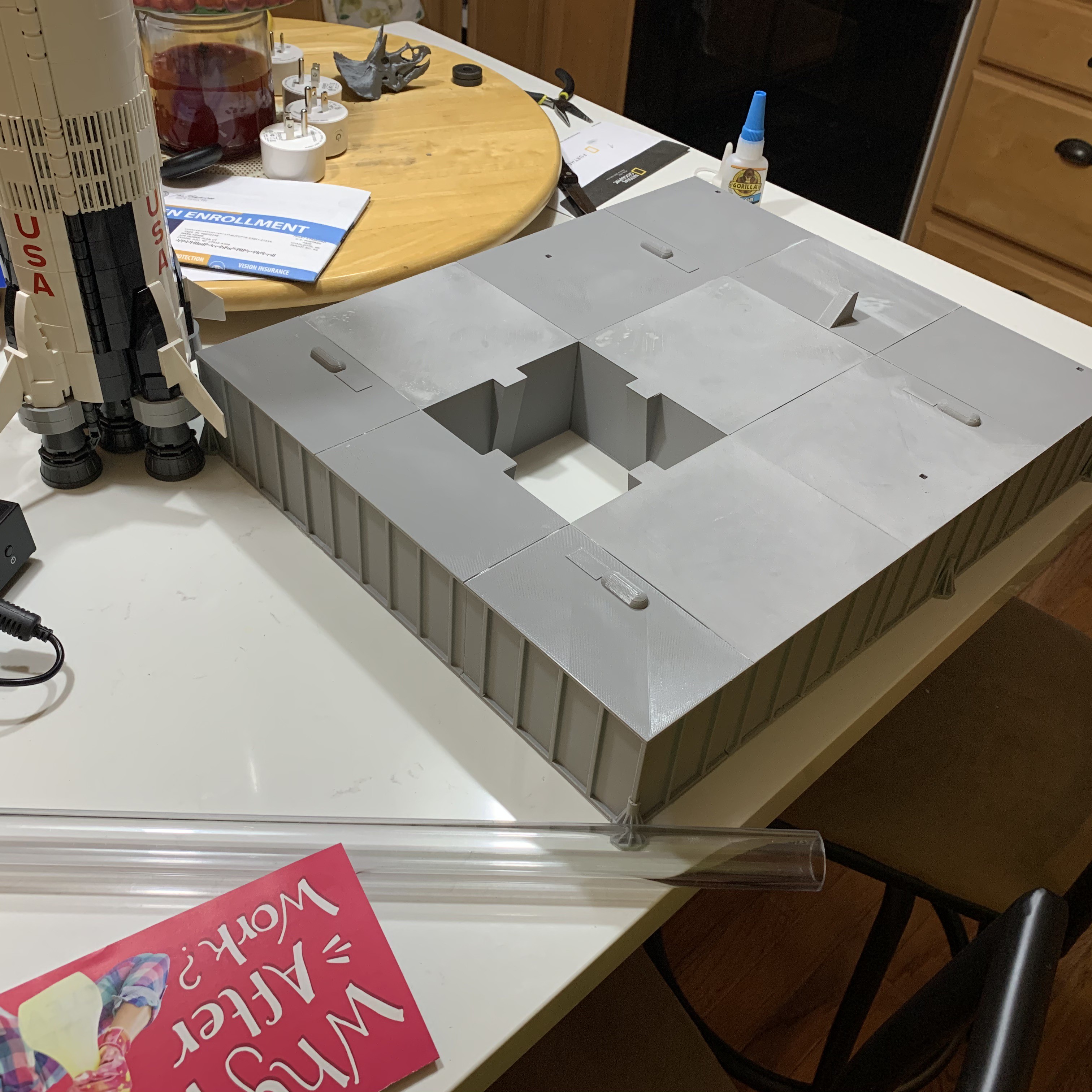
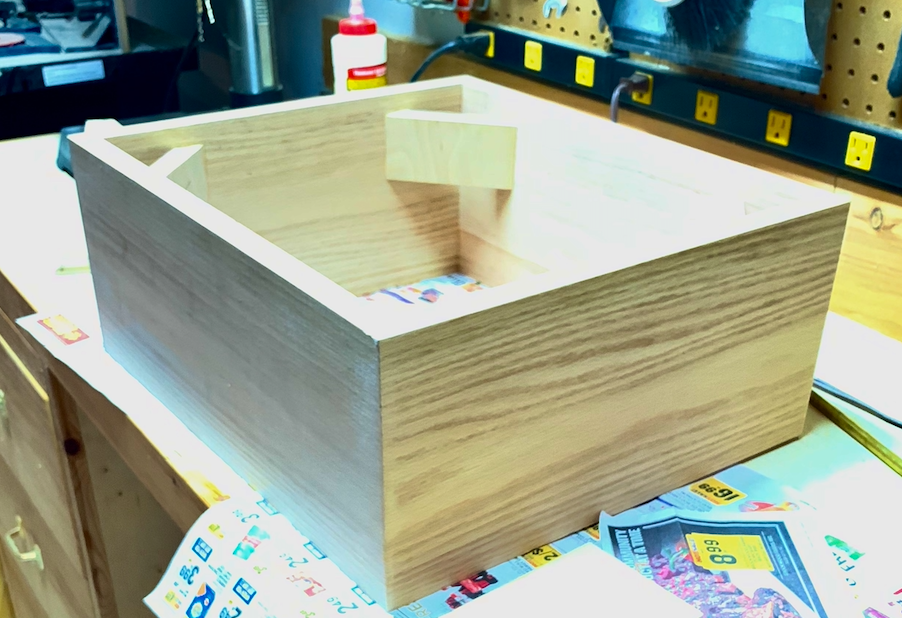
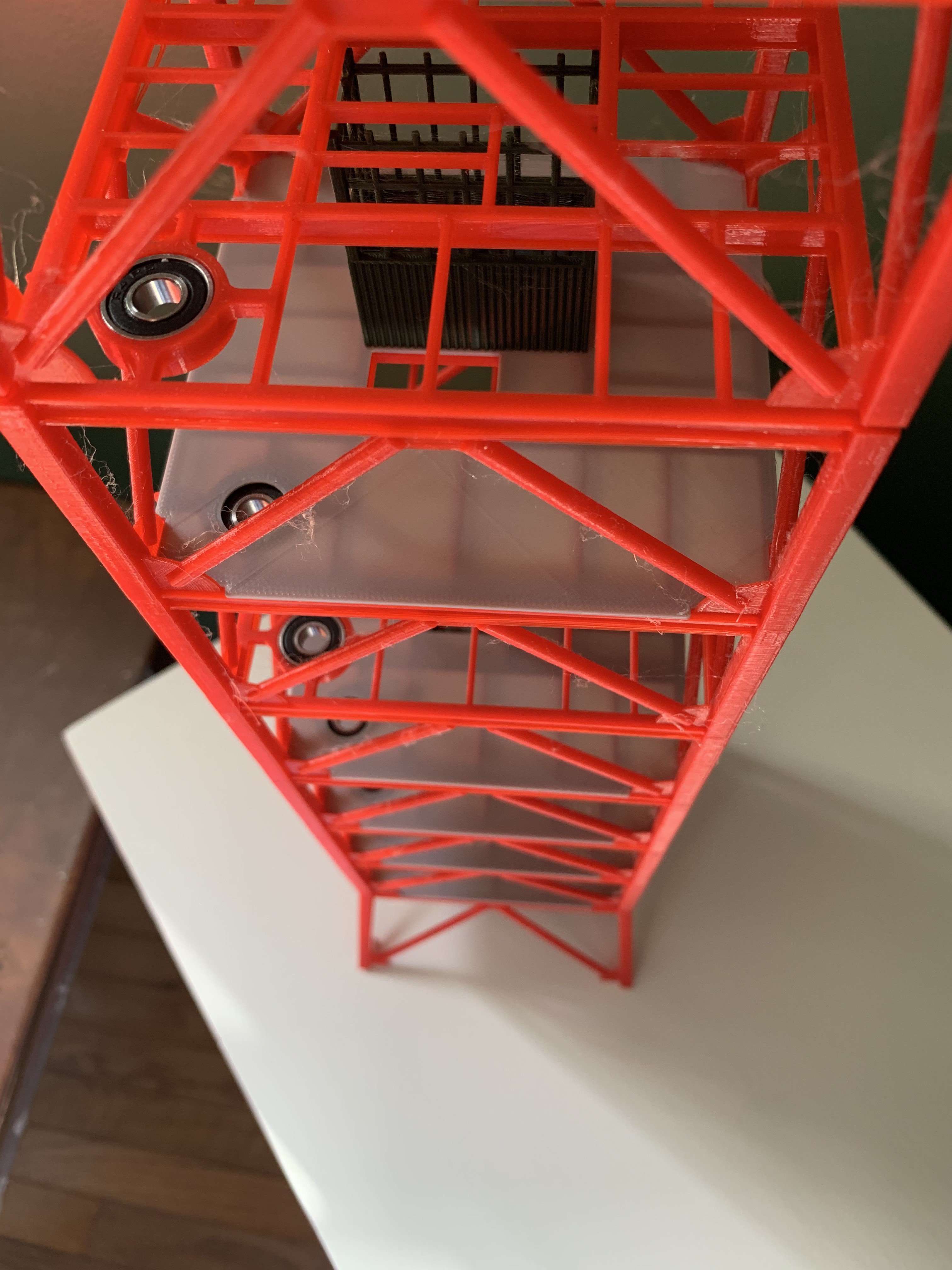
An launch pad and gantry for the LEGO Saturn V model. Crane, crew arm, gantry arms, service arms and model itself are animated for liftoff.
Become a Hackaday.io member
Already have an account? Log in.
Just one more thing
To make the experience fit your profile, pick a username and tell us what interests you.
Pick an awesome username
hackaday.io/
Your profile's URL: hackaday.io/username. Max 25 alphanumeric characters.
Pick a few interests
Projects that share your interests
People that share your interests


 Boris Landoni
 Daniel L
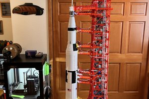
Great work ! ... Would love to get this set up in our College entrance to inspire students further into Aerospace Engineering. As someone who has just been asked to come up with ideas to inspire young people, this is excellent. Are the modified models available for print? I work with an Arduino expert and I do the CAD stuff myself, so putting together is not a problem.