Overview
This is a passion project. I have always wanted to build a balancing robot. I made an attempt years ago but it never really got the attention that it needed. Plus, life has a way of steering your attention away. Now with new found motivation, 1 or 2 hours a day, and a 3D printer, I have decided to give it another go.
Currently the main goal of the robot is for it to balance on it's own and to be controllable via a bluetooth controller. The robot itself uses similar components found on the many balancing robots scattered across the internet. An arduino platform for the brains, an IMU module to sense the robots tilt, motor drivers and motor. A list of all components used on this robot can be found in the Components section, but I will use this Project Details section to show and explain some of the components and design decisions.
Brains
The brains of the robot is a Sparkfun SAMD21 Mini Breakout board.
This module is compatible with the Arduino IDE, has a relatively small footprint and has a higher performance microcontroller compared to some of the other Arduino platforms available.
Motor and Motor Driver
The motors that were selected is the 6.3:1 Metal Gearmotor 37Dx65L mm 12V with 64 CPR Encoder (Helical Pinion) from Pololu.
The specs for this motor can be found on their website so I will not repeat it here. Originally, stepper motors were chosen but I did not like the amount current needed by stepper motors and the heat that they can generate. Since the structure of the robot will be made with 3D printed parts, DC motor were selected instead. Plus the DC motors have encoders which is used by the robot.
To drive the motors, I have selected the G2 High-Power Motor Driver 18v17 from Pololu.
Again, specs are available on their website. Now these drivers are more than capable to drive the DC motors that I have selected. I could have chosen other drivers that are cheaper and lower power, but these were selected in case I wanted to recycle them for other projects that may need more power.
IMU
The Inertial Measurement Unit selected is the AltIMU-10 v5 from Pololu.
This module has gyro, accelerometer, compass and altimeter on board. For this robot, only the gyro and accelerometer are used. Again, definitely more than is needed for this robot. It is also helpful that there is an arduino library for the LSM6DS33 3-axis gyroscope and 3-axis accelerometer IC that is on this module.
Bluetooth
For wireless communication, a generic HC-06 Bluetooth module was selected.
This module allows wireless serial communication via Bluetooth. The robot uses this to send telemetry data and receive commands to and from a PC or controller.
Voltage Regulator
The robot is powered by a 9.6v NiMH battery. Most of the components need a 5V supply, so a voltage regulator is needed. The voltage regulator selected is the 5V Step-Up/Step-Down Voltage Regulator S9V11F5 from Pololu.
This was selected for it's high efficiency and relatively high current output. An additional 33uF capacitor was added to the input of the regulator module to handle any initial voltage spikes. This is based on Pololu's recommendation for this module.
Custom Carrier Board
A custom carrier board was designed in KiCad to hold all these modules.
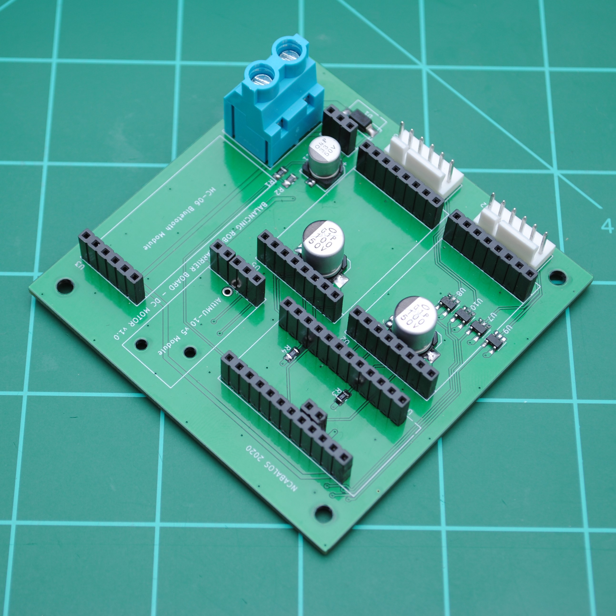
The carrier board contains some support circuits needed by the different modules:
- Capacitors for the motor drivers
- Logic level translators for the encoder inputs. The encoder signals from the DC motor is 5V and the IO on the Sparkfun SAMD21 Mini Breakout Board is not 5V tolerant.
- Reverse voltage protection.
- Voltage divider for the battery voltage measurement circuit.
- Filter capacitor for voltage regulator module
- Pull-up resistors for some motor driver signals.
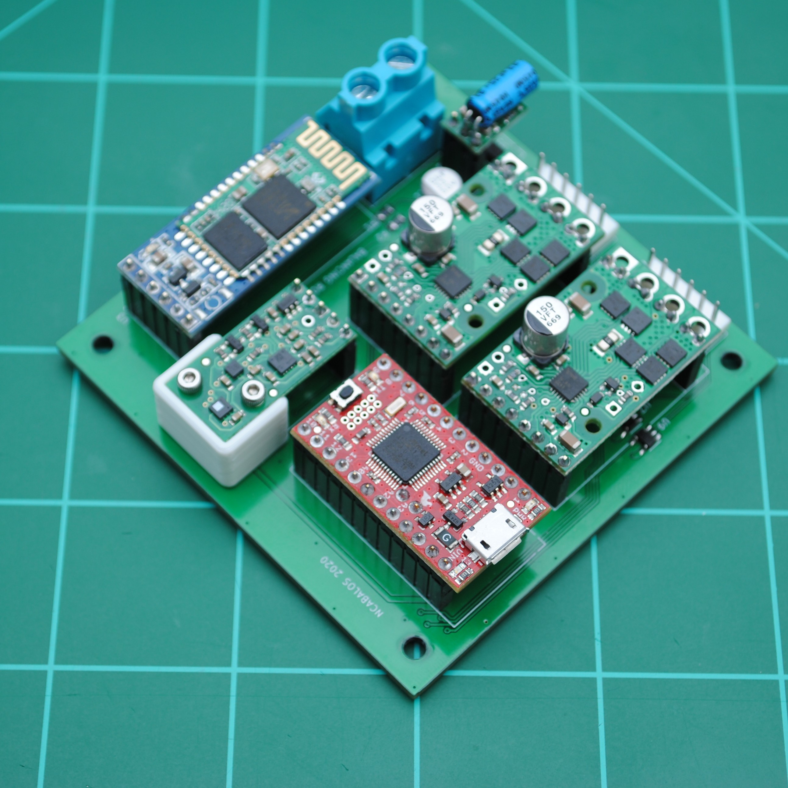
Here is the carrier board with modules populated:
 3D Printed Components
As mentioned earlier, the structure of the robot is made out of 3D printed parts. All 3D components are available on Thingiverse: https://www.thingiverse.com/thing:4685054
Wheel Base
The Wheel Base houses the motors, shafts, bearings and gears. This picture shows the bottom of the Wheel Base. This picture shows the top of the Wheel Base with the heat-set inserts. The top of the Wheel Base is where the carrier board is mounted.
Deck Riser
The Deck Riser is essentially the housing for the carrier board. It is mounted on the Wheel Base.
Battery Deck
The Battery Deck is where the battery is housed.
Battery Deck Lid
The robot is topped with a lid. The lid contains mounting points for a couple handles, an opening for the power switch and an opening for a micro USB panel mount connector. The color of the lid was unintentional. I ran out of white filament when printing the lid and the only other color I had was blue. The blue on white color scheme actually turned out good.
The following are the other 3D printed parts for the robot.
- Fenders.
- Fender Covers
- Handle Brackets
- Battery Straps
- IMU Support Bracket
- Washers
- Wheel Hub Spacers
- PCB Spacers
- Wheel Hub Spacer Tool
- Kick Stand (Optional)
Software
This section details some of the software implemented in the robot.
PIDs
The robot implements the following PID architecture:
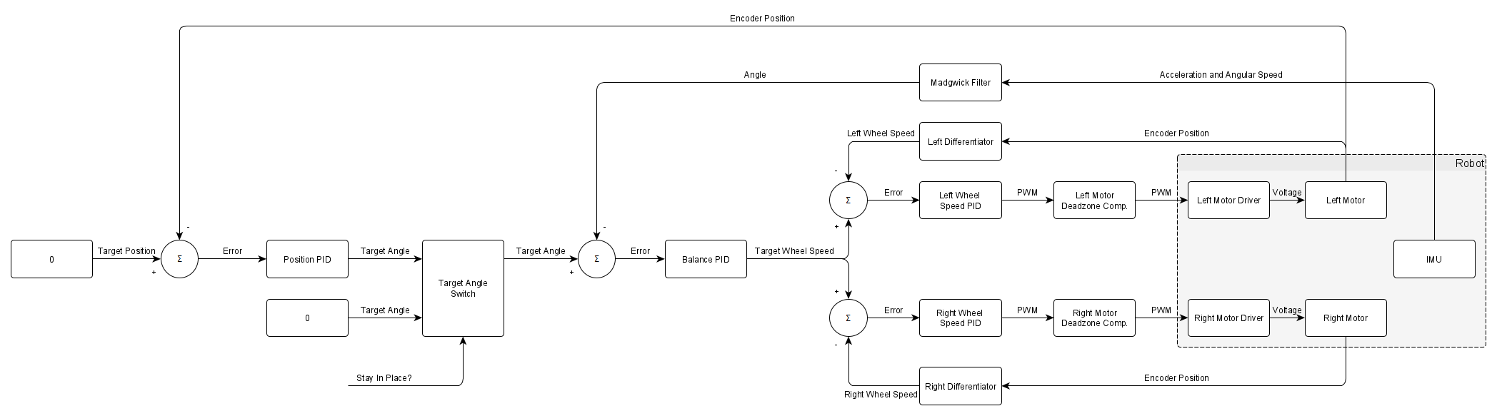
The robot uses 2 PID controllers to control the speed of the left and right wheels independently. Each PID uses the wheel speed that is derived from the encoders to adjust the duty cycle of the PWM to the motor drivers. However, the PWM output from the PIDs are fed through the Deadzone Compensation Block. The output of the Deadzone Compensation Block is send to the motor drivers. The purpose of the Deadzone Compensation Block is to compensate for any static friction in the motors. The algorithm for the Deadzone Compensation was patterned from this webpage: http://engineeronadisk.com/V3/engineeronadisk-230.html
The Balance PID controller controls the angle of the robot to keep it balanced (i.e. target angle of 0). The Balancing PID controller uses angle information from a Madgwick Filter that uses the acceleration and angular rate data from the IMU. The Madgwick Filter that the Arduino library implements is based off of the webpage: https://x-io.co.uk/open-source-imu-and-ahrs-algorithms/. The Balance PID controller outputs a target wheel speed that is fed to the speed controllers.
The robot implements a Position PID controller that allows the robot to stay in place. Currently the robot uses the position information from the left wheel encoder and outputs a target angle for the Balance PID controller. The Position PID controller can be enabled and disabled via a flag that is settable. Here is a video that demonstrates this.
Motor Deadzone Calibration
As mentioned in the PIDs section, the robot implements a Deadzone Compensation Block to compensate for any static friction that will need to be overcome when outputting low PWM duty cycles. Even if the motors are of the same model, the minimum PWM duty cycle required to produce movement at the motor shaft will be different. This minimum PWM duty cycle is needed by the Deadzone Compensation Block. The robot implements a Motor Deadzone Calibration routine that can obtain these minimum PWM duty cycle values.
When the calibration routine is executed, the duty cycle will be ramped in the forward direction. The ramp will stop when encoder edge transitions are detected. The PWM duty cycle number is recorded for the forward direction. The duty cycle will then be ramped in the reverse direction, only stopping when encoder edge transitions are detected. The PWM duty cycle number is recorded for the reverse direction. This will repeat 4 more times. After the final iteration, all the PWM duty cycle numbers will then be averaged and displayed. This routine will then need to be executed for the other motor.
Once the PWM duty cycle numbers are obtained, they can be used in the Motor Deadzone Compensation Block.