 Bud Bennett
[Edit 2021-09-25: Changing approach to include PIC micro-controller. See latest log entry.]
I have accumulated quite a few LiPo and Li-Ion battery packs in the last few years. I have a pretty good 200W battery charger that can charge four batteries simultaneously, but sometimes I would like to charge a few more in parallel to speed up the process. There are parallel battery charging fixtures available from several manufacturers that can do the job. All of them require that the state of charge of the batteries be pretty close before connecting them in parallel to avoid potential catastrophic failures: smoke, fire, explosions. These fixtures include fuses between the batteries which open if too much current flows between the batteries, preventing the catastrophe. One fixture provides a battery checker that displays the battery voltage so that you can ensure that the batteries won't be too far apart in voltage before inserting them into the fixture. All of this relies on the user to know what he is doing...and what's the point? If there is a battery that is discharged deeply, you will have to charge that battery individually anyway since it cannot be connected to the others that are only moderately discharged.
I think there is a better way.
First, a bit of background.
Way back in the last millennium, I was designing battery charger ICs for Linear Technology Corp. I believe that I designed the first commercial Ideal Diode implementation into the LTC1960 and LTC1760. (I may be wrong about that, but if you don't toot your own horn nobody will toot it for you.) It wasn't called an Ideal Diode. There were 5 of these "low forward voltage diodes" on these two chips. It worked beautifully!
Later, a very capable IC designer working for me turned the concept into the LTC4412 "near" Ideal Diode Power Path Controller as a stand-alone part. The LTC4412 is now listed as an Ideal Diode, and it has been copied by others. The Ideal Diode power path controller is integral to this approach.
[Edit: 2021-07-04 Last week I was reminiscing with that "very capable IC designer" (who is now something of a legend at ADI/LTC) and we decided to see if there were any other commercial implementations of the "Low Loss" diode ORing concept prior to the above mentioned parts. There is a 1999 patent from Boeing that comes pretty close. There are claims made by the Boeing patent that might cover our invention. But neither he nor I was willing to pursue a patent -- we already had more than ten patents each, and the hassle of dealing with the corporate patent lawyers and the US patent office did not appeal to us. In any case, LTC was not sued for any infringement. Besides, Boeing is not really a commercial endeavor and tends to keep its innovations to itself, preferring to sell planes rather than systems or circuitry.]
Problems to Solve:
- Mismatched batteries should not charge or discharge each other with high currents.
- The charger performs a simple "sanity check' on the connected battery before committing to perform the charging operation. I believe this is just checking voltages at terminals to see if there is a battery connected. If the voltages and impedances aren't within acceptable limits, then the sanity check fails and the charger aborts.
- After the charging begins there is some additional sanity checking. If the impedance on the balance leads is not correct then the charger aborts soon after beginning to charge the battery.
- The charging station must survive a careless user: there must be no requirement to connect batteries or balance leads in any order, swapped balance leads should not destroy components. Dead cells or bad cells should be handled safely.
This parallel charging station must fool the charger into thinking that all is well.
The Schematic to date:
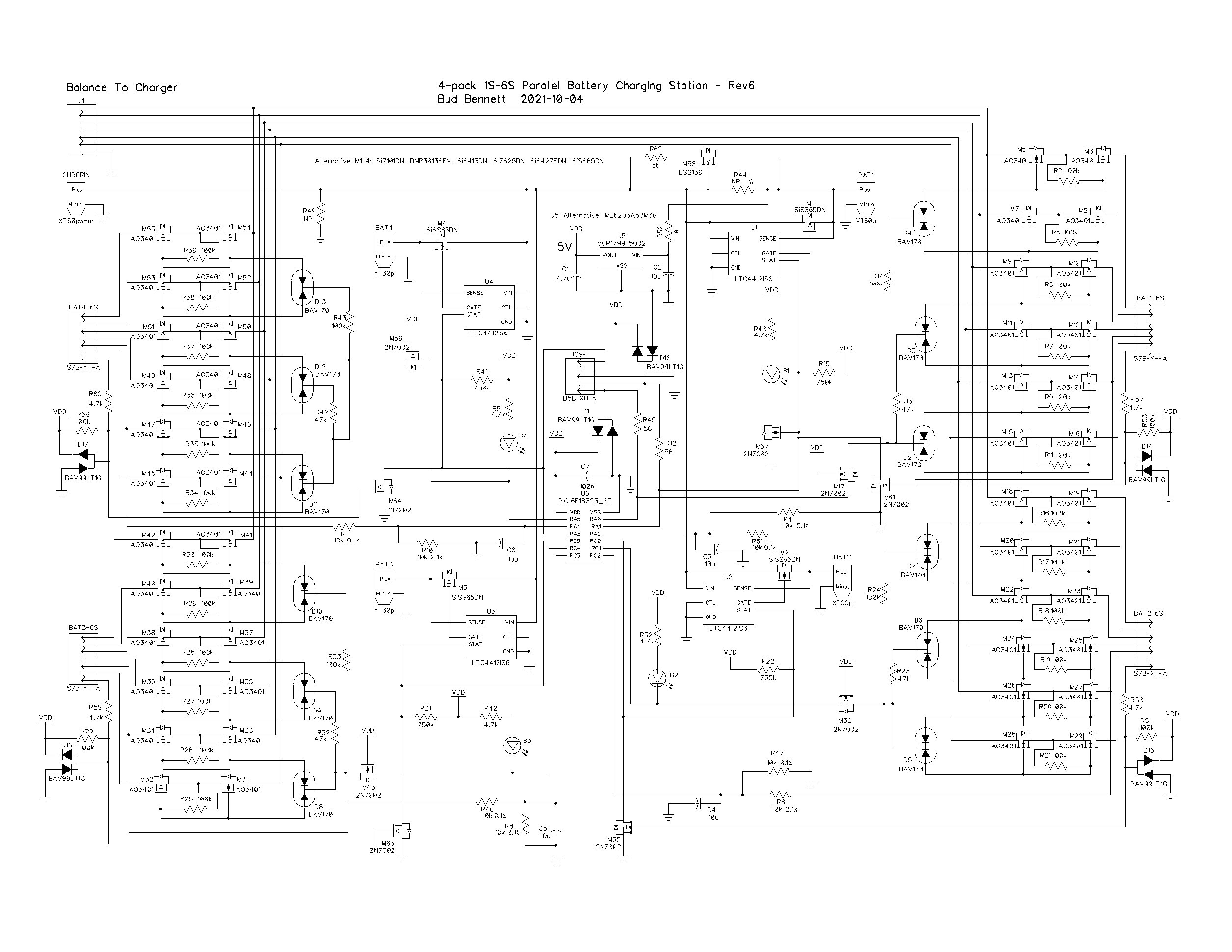
This fixture will charge 1S-6S LiPo, LiFeSO4, Li-Ion, or LiPoHV packs, as long as the cell counts are the same. I'm not sure that it would be a good idea to charge any Nickel-based batteries in parallel.
Theory of Operation:
There are four LTC4412 ideal diode circuits to connect the charger to the four batteries to be charged. The ideal diodes prevent batteries with higher charge states from sourcing currents to batteries with lower charge states. When the charger current/voltage is applied to the main input the battery with the lowest voltage gets all of the current. As this battery's voltage increases the other batteries eventually will share the charger current among them, according to their relative capacities (i.e. if a 2000mAh battery and a 1000mAh battery are connected and the charger is providing 3A, then 2A will flow to the 2000mAh battery and 1A will flow to the 1000mAh battery.) The only real restriction is that all of the batteries must be the same chemistry and cell count. The ideal diodes keep the power dissipation to a minimum (3A*3A*10mΩ = 90mW). This is a huge improvement over using ballast resistors to even out the current distribution between batteries, but not as good as fuses.
The LTC4412 STAT pin goes high when it begins to source current to the battery. The B# LED is lit as well. This output is also used to connect all of the balance leads of that battery to the balance leads of the charger with low resistance PFETs. Batteries that are not receiving current have their balance leads disconnected.
Rev3 added a battery detection circuit to inhibit the B# LED if the battery is unpopulated. The GND lead of the balance connector has a 100kΩ resistor pulling to 5V. It drives the gate of a transistor that inhibits both the balance leads switches and the LED indicator. If the balance leads are connected this pin is grounded when the battery is plugged into the charger connection and removes the inhibit.
As the LEDs light up to indicate which batteries are receiving current, the user can either increase the charging current, or let it continue with the same settings until charging is complete, but it might be a much longer charging cycle. (It would be really nice if the charger was capable of a two-step sequence of charging currents: a lower current until an indicator is asserted, and then a higher current afterward.)
What happens when:
- BAT1 is inserted first? BAT1 will supply current to all of the electronics. The charger is not supplying current at this point, so the voltage at CHRGRIN will be lower than the voltage at BAT1, so the STAT pin of U2-U4 will be low. The balance leads will be disconnected from BAT2-BAT4 and BAT1's balance leads are connected. The charger thinks it is connected to BAT1.
- BAT1 is not inserted first? It will still power up all of the electronics, but the balance leads of BAT1 (and others) will float and the charger will detect a failure during its sanity check phase.
- The balance leads of a battery are connected prior to the main lead? The battery present detection scheme disconnects the balance leads until the battery is plugged into the XT60 connector. The PFETs are off so they are just back-to-back body diodes connected between the cells – no current can flow between them.
- The main lead of a battery is connected prior to the balance leads? If BAT1 is in place then it depends upon the charge state of the additional battery:
- If the additional battery is higher voltage than any others, then the LTC4412 will prevent current flow to/from the battery and the balance leads are disconnected.
- If the additional battery is lower voltage than the others, then it might draw limited current from BAT1, via M58, and assert the STAT pin, but since the balance leads have not been connected yet the PFETs in the balance lead mux are turned off by the battery detection scheme. The balance leads are disconnected, so no high currents flow.
- BAT1 is in place, but some batteries have swapped balance leads into their respective connectors? The ADC in the PIC micro-controller monitors the voltage at the 2S balance lead connection. If the ADC determines that the voltage of an unconnected battery differs by more than +/-100mV at that 2S connection it will refuse to connect the battery until the voltages are within +/- 100mV.
- A battery with a dead cell is connected? This battery will probably have the lowest voltage of all the other connected batteries, therefore it will be the only battery with its balance leads connected to the bus and the charger will flag a fault during its sanity check.
- A battery with a bad cell is connected? A bad cell has a large potential difference from cells in the other connected batteries. The situation depends upon how large the differential is. The PFETs switches in the balance leads have a typical on-resistance of 50mΩ and claim to handle 2-4A of current, so the maximum differential voltage they could withstand is around 300mV, if you assume that the ESR of the battery is about 50mΩ as well. But bad cells typically have higher ESR (that’s why they’re bad) so the maximum differential voltage could be a bit higher than 300mV.
- The user mixes cell counts of batteries attached. What happens next depends upon the charger. The battery with the lowest cell count will probably be connected to the charger. If the user has programmed the charger for a higher cell count then the charger will not detect the higher cells because they are not connected by the balance lead mux -- the charger will abort. If the charger automatically detects cell count, then it will only charge the lowest cell count battery and terminate without ever connecting the higher cell count batteries.
Fooling the Charger:
The charger checks the main lead and balance leads for voltage before charging can commence. The balance lead mux will connect the lowest voltage battery's balance leads to the charger. If BAT1 has a lower voltage than the other connected batteries, then it will be connected to the balance leads of the charger and the charger output. If BAT1 is the only battery connected, then its balance leads will be connected to the charger.
This subterfuge requires that BAT1 must always be in place when charging parallel batteries. It is a small, but necessary, price to pay.
Design Considerations:
Failsafe Design:
[Edit 2020-12-21: Removed the poly fuses...because...fuses are for weenies.]
Connectors and Headers:
I decided early on that it would be cheaper (and just as good) to just purchase a few balance lead expander boards rather than integrating all of that into the parallel charger PCB. A balance lead expander board costs just over $1, and is available from many sources:
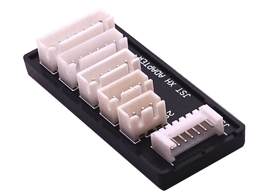
You must pay close attention to the pin order of all of the connectors. The wire lead harness that connects the expander to the charger uses a JST-HX plug at the other end. Similarly, all of the connector/headers for the batteries are JST-HX. But Pin7 on the HX connector is GND and maps to Pin1 on the CJT connector. Beware!
Sizing the ideal diode PFET:
A 6S LiPo battery is 25V when fully charged, so 30V BVDSS should be enough. My batteries range from 550mAh to 7Ah in various cell counts. The recommended charging current for the 7Ah Li-Ion battery is 1/2C, or 3.5A. I have a 5Ah 3S LiPo that can be charged at 5A. I figure that a reasonable current capability for the ideal diode PFET is > 10A, with a reasonably low RDSon < 10mΩ. It should also have a low threshold voltage spec since the LTC4412 limits gate-source drive to about 7V. There are basically two package types to choose from: a 3.3x3.3mm DFN or a 5.6mm DFN. I chose the smaller package -- thermal resistance should not be a problem here.
After searching on LCSC and Digikey, I listed a set of PFETs that should work well in the application and allow a minimum charging current of at least 10A/battery. The PFET that I think is best for this application is the Vishay SiSS65DN: typical Rdson ~ 5mR, it also has a very low Vth ~ 2.3V, with a junction-ambient thermal resistance around 25 C/W.
Driving the Balance Lead PFETs:
The AO3401 PFETs cannot tolerate more than 12V between the gate and source, so the voltage must be limited for protection. I decided to use a simple voltage divider and some diodes to limit the gate-source voltages across the PFETs. The voltage sharing is not perfect, but a ±2V variation around 9V should not be a problem.
The gate-source resistors are 100kΩ. I had to use low-leakage (5nA) BAV170 diodes to avoid leakage currents from turning on a PFET at high voltages. The aim is to keep the stray currents not going to charging the battery from confusing the charger near the end-of-charge cycle.
The 5V Regulator:
I switched to a SOT23-3 regulator -- MCP1799-5002. It has a low bias current and can hold off 45V. The input an output capacitors are quite large (both in value and size). As an alternative you can substitute the ME6203 from LCSC. It has similar specs, but doesn't include a thermal limiter. The MCP1799 uses smaller input/output capacitor values as well. I put a 100R resistor in series with the input of the regulator -- this is to prevent latchup, but since the MCP1799 can withstand an absolute maximum input voltage around 66V this resistor will probably be shorted.
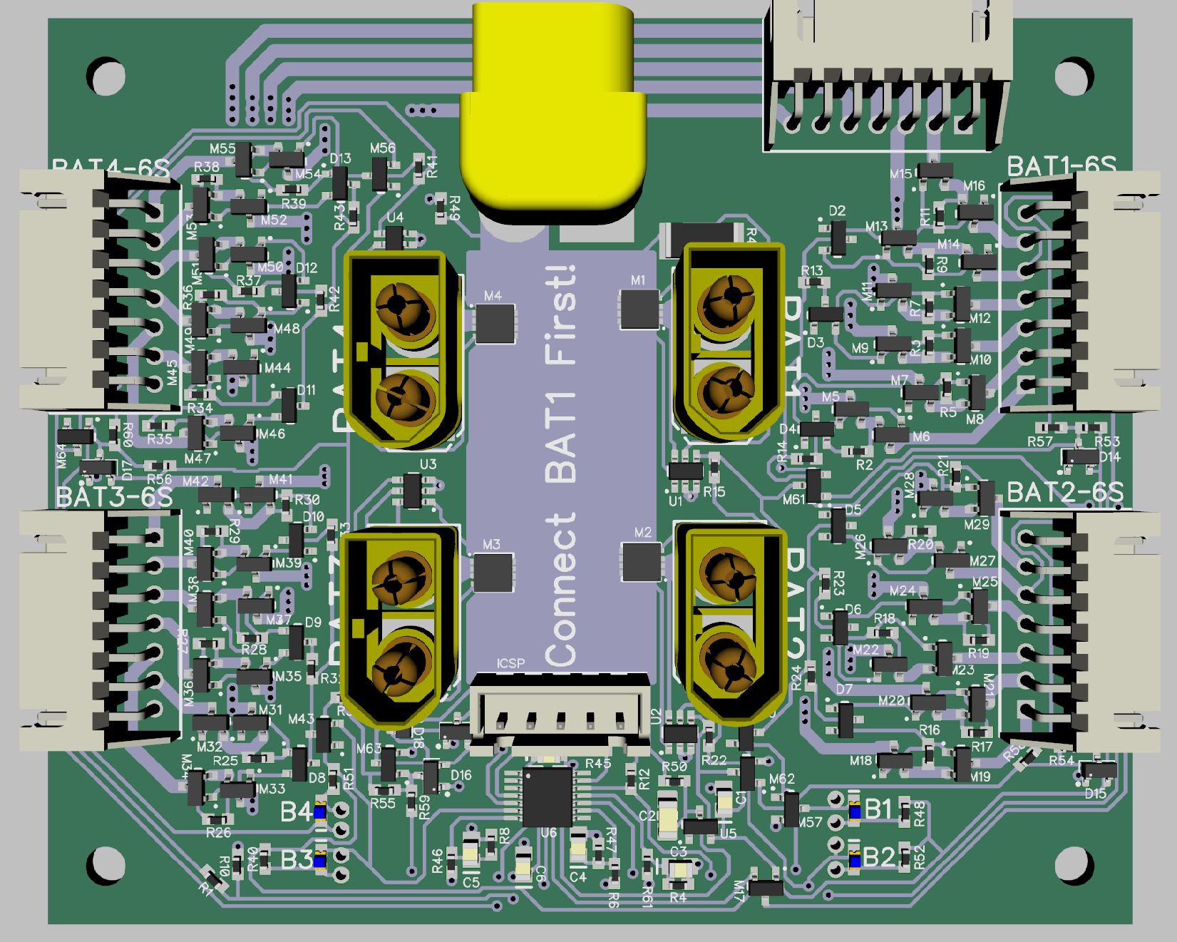
The PCB Layout:
Dimensions: 95mm x 80mm. I specified the standard 1oz. copper since I can get some really large widths in the space available. 0603 LEDs are used for the B# indicators in the lower left corner. This is the Rev. 6 PCB layout with PIC micro-controller. The BAT# LED indicators are re-arranged to match the locations of the attached batteries. This should make it more intuitive to determine which batteries are charging. The charger balance lead connector is changed to a JST-HX type, which is much more ubiquitous. I also flipped the right-angle XT60 connector to the top side to make the bottom side flat -- easier to make an enclosure.
Layout Considerations:
- Trace widths:
- I did not want to add the expense of 2oz. copper, so the traces are pretty wide in general.
- The charger positive input is expected to carry >20A. The trace is 16.6mm wide, which is the minimum required to keep temperature rise below 15°C for 1 oz. copper traces. I figure that the sheet resistance of 1oz. copper is 1mΩ/square; there should be only about 2mΩ between the charger input and the farthest battery.
- I have no idea how much current will be sourced to the balance leads, but the connectors are only rated for 3A. A 1mm wide trace should handle 3A with a 15°C rise.
- I ran traces on the top and bottom layers for the 1S-4S balance leads. This was just to keep the trace resistance low for the batteries that I use the most. I did not have room to do that for 5S-6S leads.
Status:
Received the Rev.6 boards on 2012-10-20. I added the PIC16F15223 and programmed it in-situ (after several failed attempts) using the ICSP connector. It seems to be fully functional and meet expected parametric tests.