 Eben
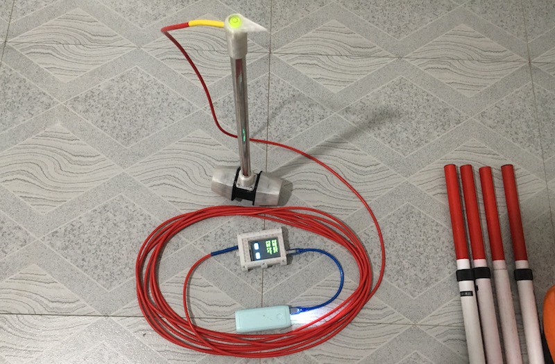
EbenField Test:
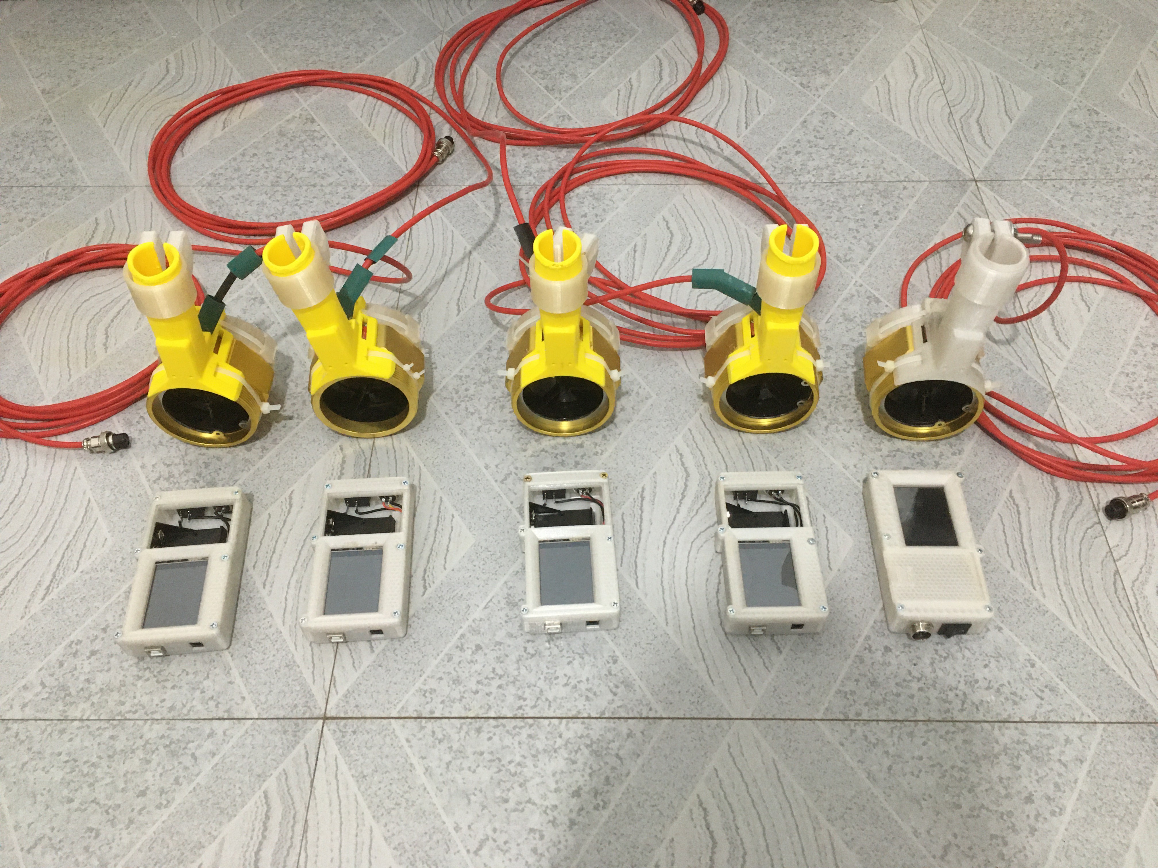
They are multiplying:
The build 20th of January 2021:
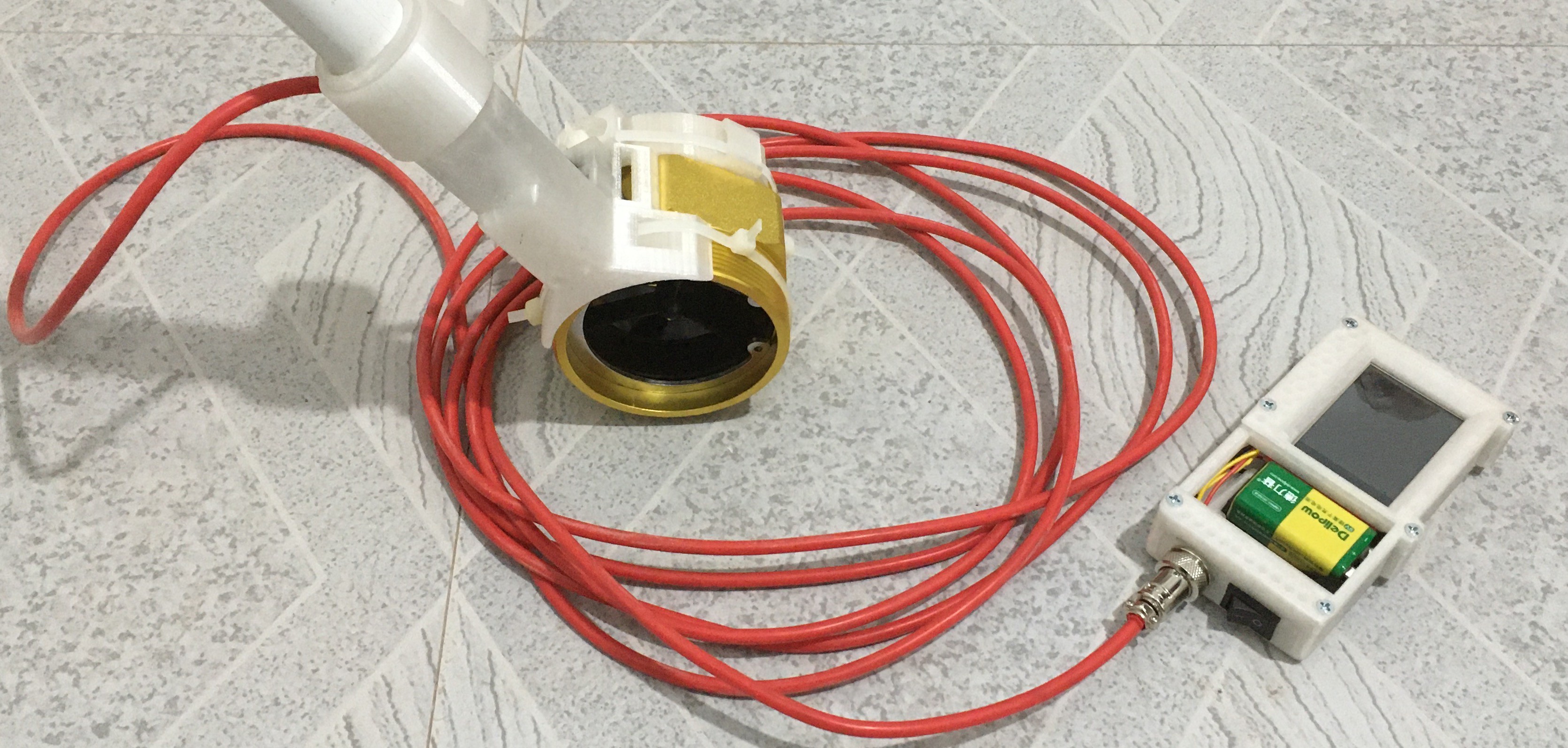
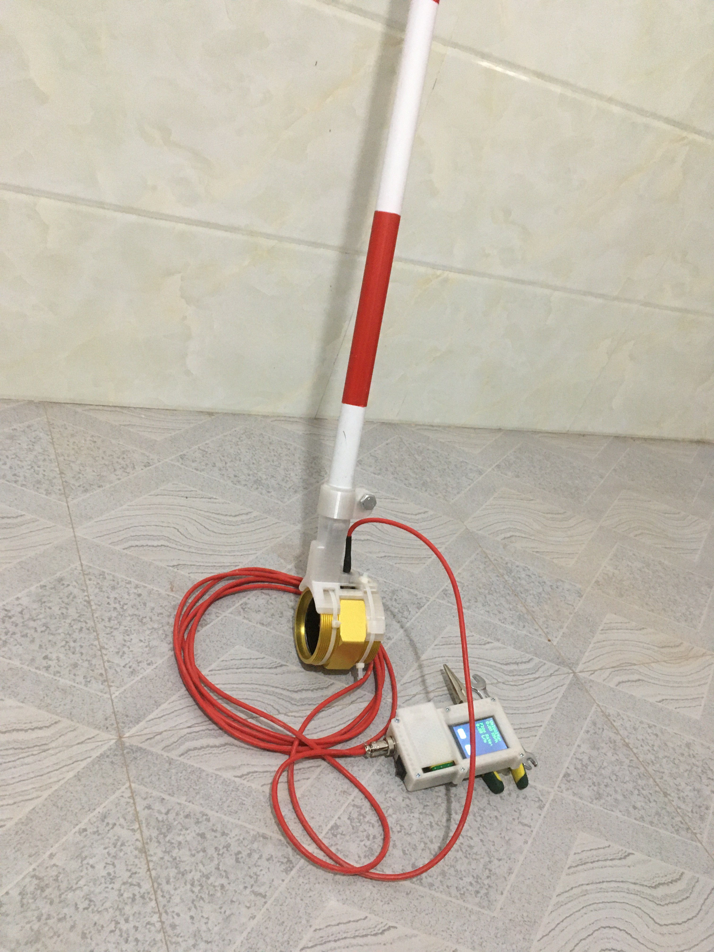
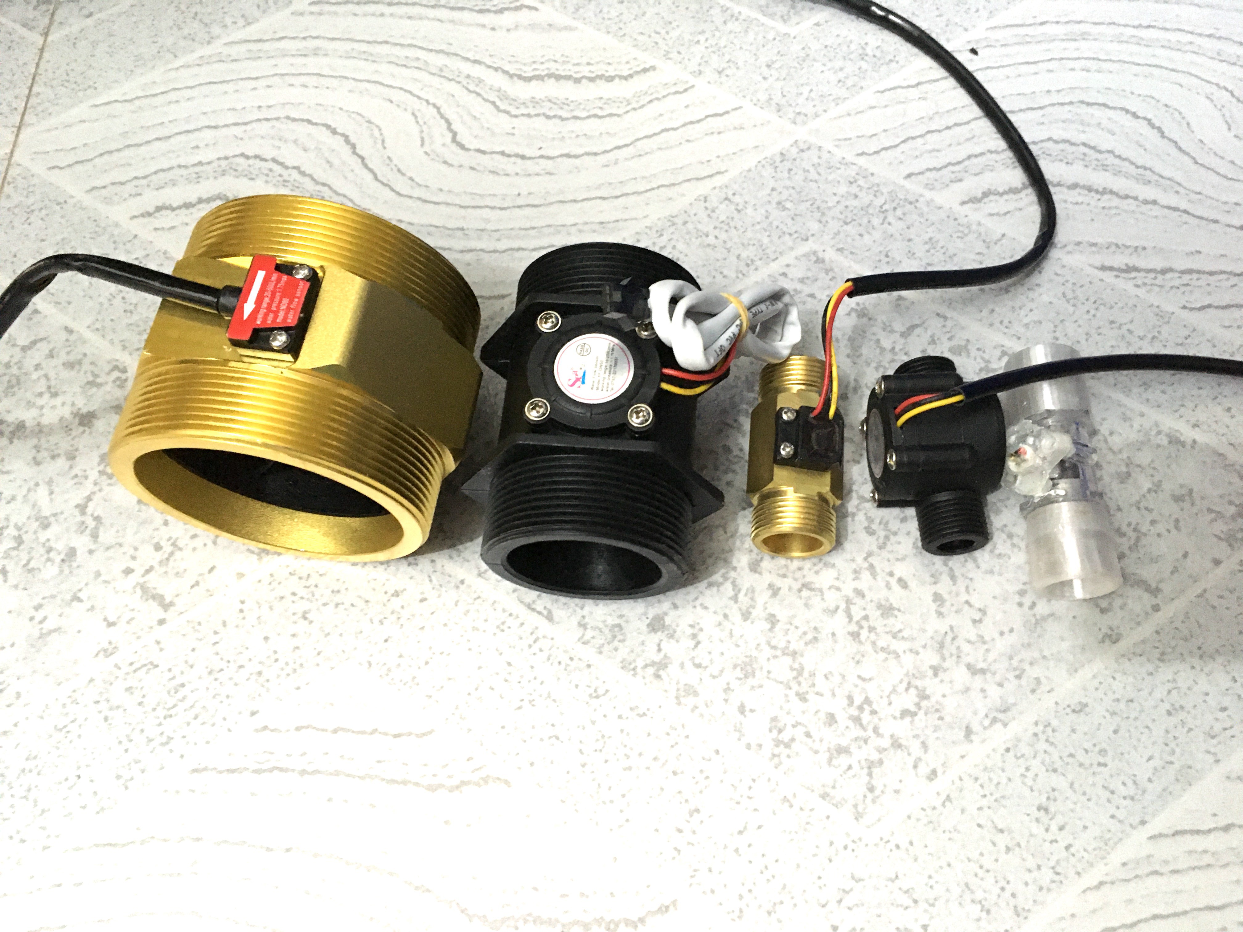
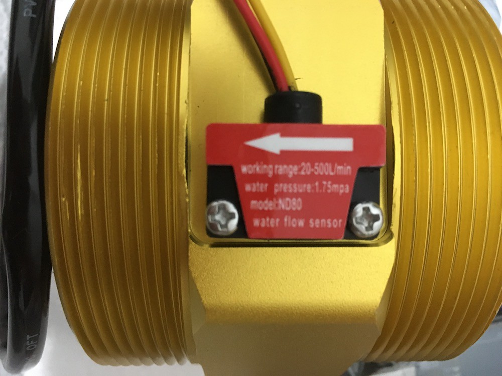
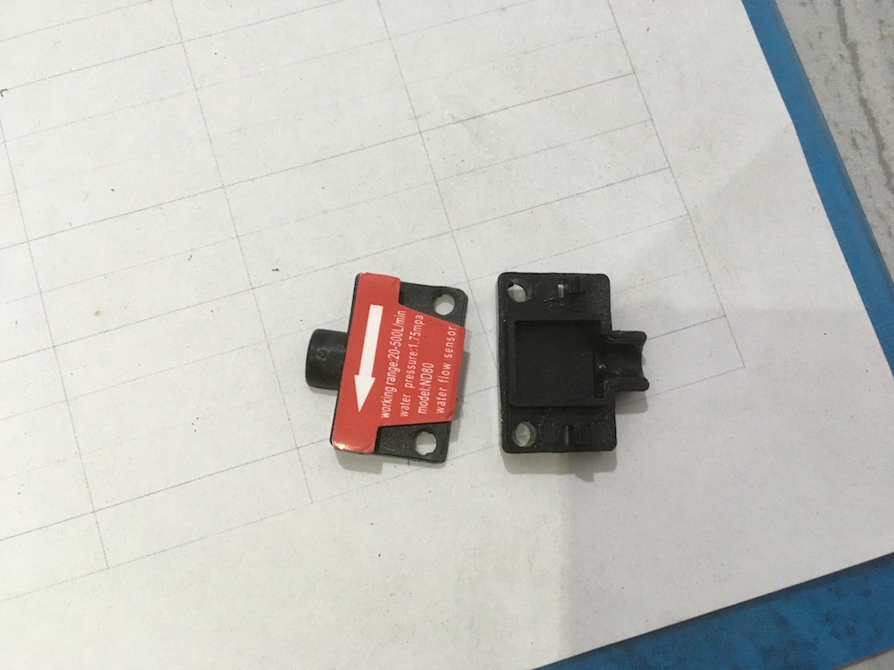
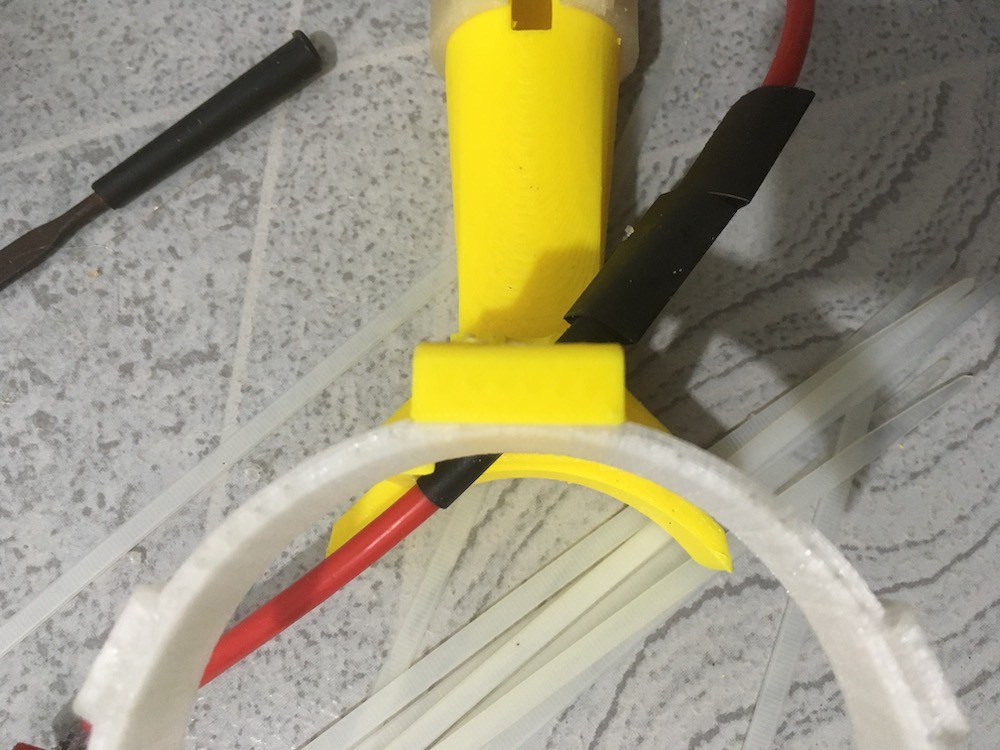
Improvements since the DN50 build: Internal battery housing, on/off switch, aviation connector, DN80 sensor, detachable sensor pole.
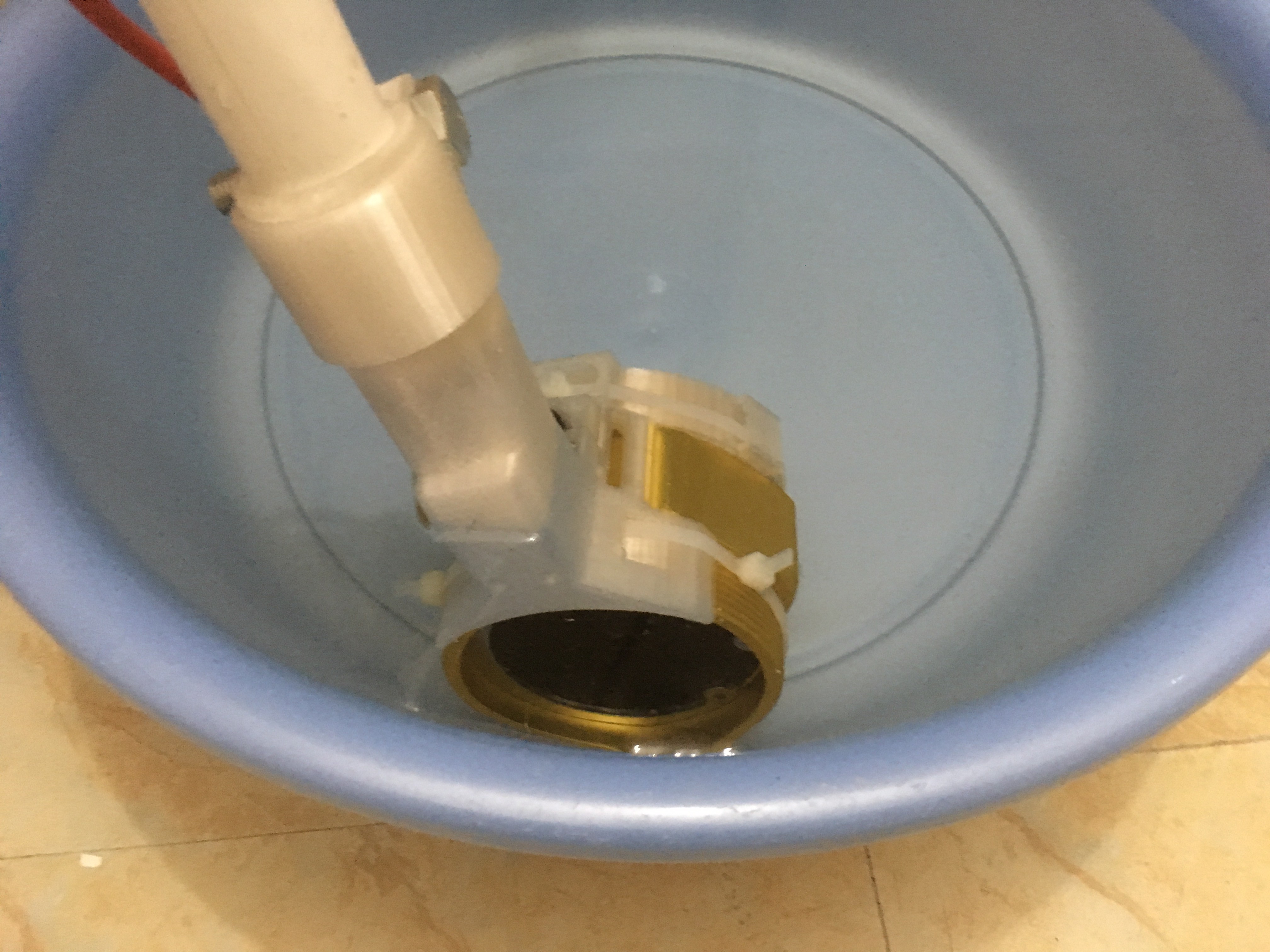
Here is one of the earlier designs using an DN50 sensor.
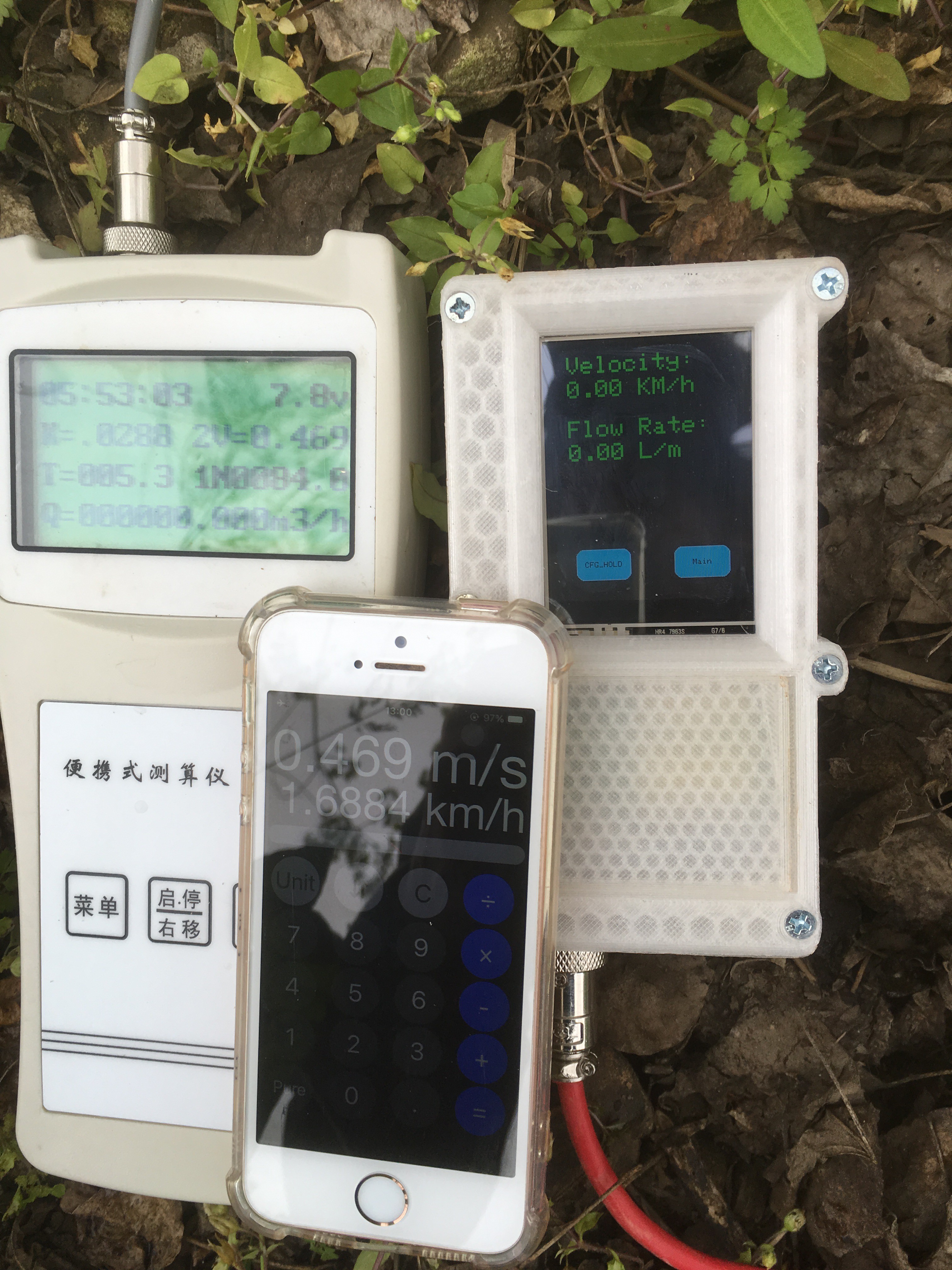
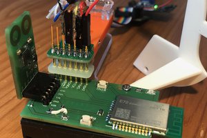
I have switched to using a DN80 sensor, I have created a new Arduino housing that now has an on/off switch, an aviation connector for the main cable and internal battery housing. I'm working to change the firmware to read MPS instead of Km/H.
After that I will do some tweaking comparing the readings with a purpose build flow meter to increase the accuracy. If all of these steps go as planned then I will complete the build instructions and finish this project.


 Alexander Dvorkovyy
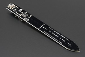
 Valentin Ortega
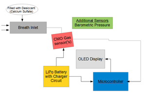
 Tom Meehan
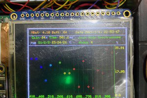
Great design and appreciate you sharing the information. It appears from the sketch that you are taking 10 one second readings and then averaging them. Did you find a significant variation between the one second readings? Thanks.