 Daniel Nikolajsen
A simple satellite antenna rotator with an android app that calculates the position of any satellite using its "kepler elements", and sends the relative direction to the Az-El antenna rotator to track the satellite across the sky.
Controller
The onboard microprocessor is an ESP8266 NodeMCU board with wifi-capability that can be controlled manually in a web-interface, with the free android app available from Google Play or with a PC running Gpredict or other software capable of sending rotctl-commands over a network.
/ Daniel SM7YSA


 Andy Lee
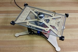
 Tim
Tim
 Supplyframe DesignLab
 Val
Val
impressive work, well done!
Regards: Versatile Digest