 Victor Chan
Prologue
Original version of this clock started around March 2017. This happened by somewhat of a coincidence, as I noticed that the bedroom clock seemed to slow down quite noticeably only after a few weeks. That and the annoying task of replacing batteries every 6 months or so definitely didn't help. This was where a decision was made to build my own clock.
Initial Design
Firstly, the main goals of the design were determined. They were very basic and simple:
- Accurate
- Maintenance free
- Versatile
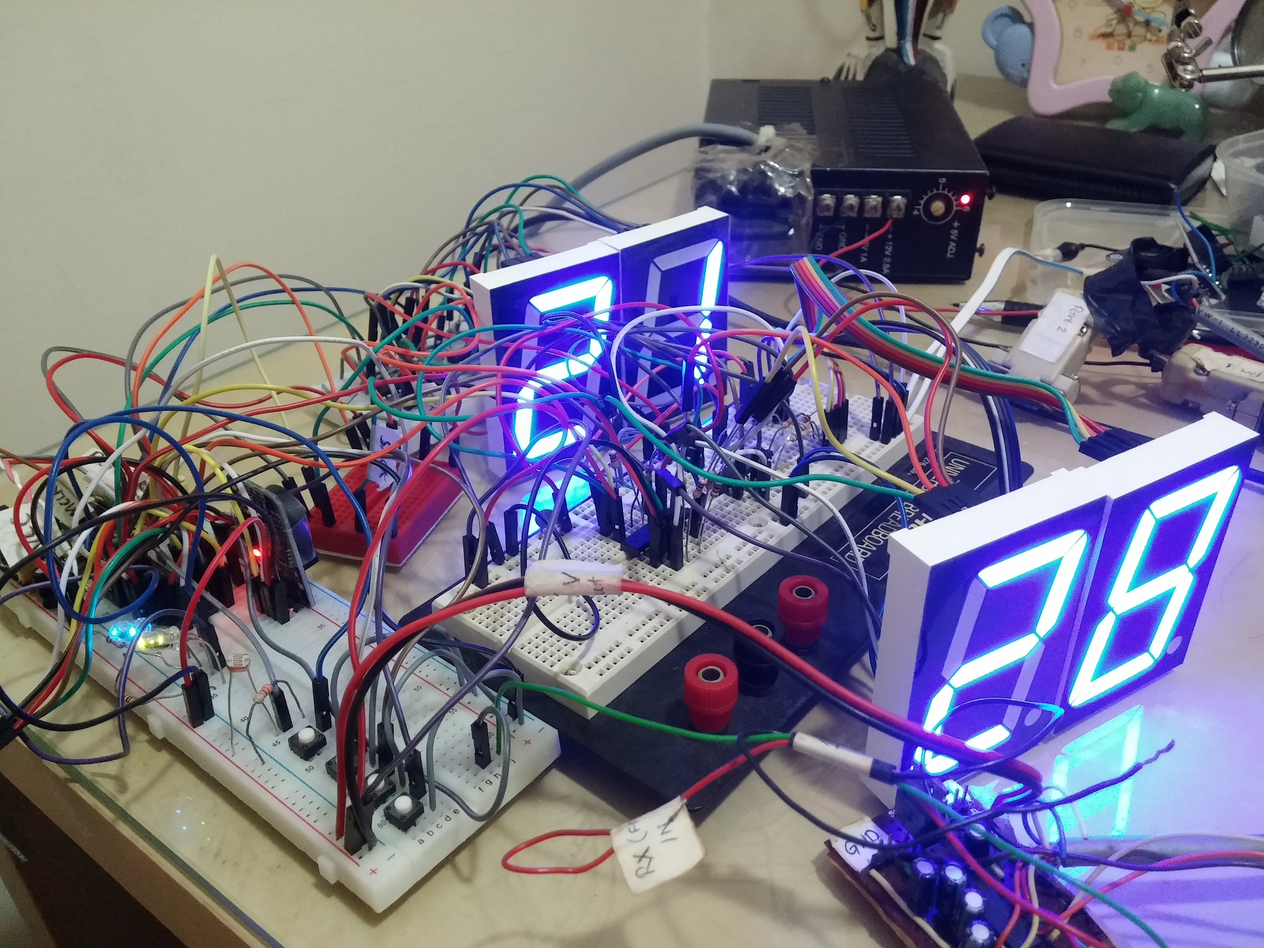
Design was carried out on a breadboard with simple jumpers and LEDs with the 3 goals in mind. GPS was used for accuracy. Even though higher accuracy can be achieved with the timing coming off the PPS signal, this was not possible without embedding the GPS module directly onto the clock. Thus the GPS module (puck) for automotive navigation systems were the obvious choice. It is easy to use and outputs the NMEA strings which can be easily parsed by the MCU. Only the GPRMC and GPGGA strings are recognized as they contain the data fields we needed. Accuracy of around 0.2s or less can be easily achieved. This is not an issue as the main goal is for normal daily time keeping, and not for time recording of critical machine / equipment events (which may often need to be 10 ms or better).
Main maintenance item would be the battery. Getting rid of battery is a big thing for me. Time accuracy is not so much of an issue as GPS data will provide the corrected time once lock is obtained. However, to be useful, the clock should be able to run even when GPS lock is not available. Simpler implementations that solely parse the GPS data for time display will be unable to display the time when there is no GPS data. This is where the RTC helps to keep the clock running (free running mode). Updating the firmware was also an important consideration. Therefore, the 5 pins for ICSP are provided so that new firmware can be easily flashed.
There were a few important items under the versatile category:
i. Large display - the 2.3 inch digit size chosen is the ideal size for this use case.
ii. Readability - LED brightness must adapt to the ambient lighting accordingly. Otherwise, it may be too bright at night and dim during the daytime.
iii. Power needs - single power source for the electronics and the 2.3 inch LED display. The clock MCU, RTC and RF module all run at different voltages than the LED display.
iv. Seamless operation - the nearest window from the wall where the original clock hung was not conveniently near enough to pull the GPS antenna module, without messy long wires. This meant that the data must be wirelessly sent to the clock. NRF24L01+ is the perfect candidate for size, ease of use and cost.
v. Constant time keeping - living in a high rise building with other similarly tall buildings nearby pose some challenge to the GPS signal stability. Therefore, GPS signal outages are expected. Depending solely on the NMEA string to provide time also means that the RF module has to be powered on at all times. The solution? DS3231 RTC.
vi. GPS info - since it runs on GPS, it is useful to know how strong the GPS signal is being picked up. Looking at the FIX LED will not provide much info besides when it does or doesn't have a FIX. Therefore, the satellite count / quantity will be more beneficial. This is implemented on this clock.
Parts Selection
Main technical challenges were parts selection, testing and debugging. So, let's see what has to be right in the design and my choices for the parts selection:
i. RF module : Decent range in the ISM band, which immediately restricts it to 2.4 Ghz. Widely used and fairly easy to work with. Doing some research, I kept coming back to the Nordic Semiconductor IC based module, NRF24L01+. These have been on the market for a number of years and a decent amount of documentation were available.
ii. RTC IC : Accurate and since GPS can provide date, preferably it includes a built in calendar. DS3231SN from Maxim seems like a good match. It is TCXO, which is a bonus for good time keeping accuracy. The initial version was using a ready made module from Aliexpress.
iii. Shift register : The xx595 family of shift registers are a logical choice since I do not have nearly enough individual output pins to control each pin on the 7 segment LED. There are 6 of those (HH, MM, SS). Looking at the 2.3 inch LED spec, it has a Vf of about 11V at 3mA to be sufficiently bright. Therefore, the common anode type was chosen. The TPIC6B595N IC serves this purpose well. Each output can sink up to 150mA which can handle bigger loads if needed. Plus, it has an output enable pin which can fed with a PWM signal to control the dimming!
iv. Photoresistor / LDR : There are so many of these, and without any knowledge of what specifications were needed, I ordered 2 versions (looks exactly identical, but different specs). These were GL5516 and GL5528. After some testing and biasing them with several values of resistors, GL5528 was chosen.
v. MCU : Since I am quite familiar with PIC products, 18F24K22 was selected. It has SPI for the RF module, I2C for the RTC, analog input for the LDR, serial port for direct GPS connection, PWM capability for LED dimming, sufficient output pins for the shift registers and input pins for the clock settings. For the GPS RF board, the 16LF1554 was chosen for the low power needs and the simpler design.
First Version
The first version of the clock was completed but consisted of several separate parts. These were the main clock board, the remote GPS RF module and the display board (7 segment LEDs and TPIC6B595N IC). Getting the LDR values to have enough range from very bright to very dim conditions meant a lot of nights were spent tweaking the resistor values and code to make it right.
Getting the RF module to work was a real challenge as there was nothing I could see to confirm. Working over SPI made it even harder, unlike serial. It was mostly trial and error. It could be the TX module was not set up right or the RX module was configured wrongly. So when it finally worked after weeks of testing it was a real fist punching in the air kind of moment!
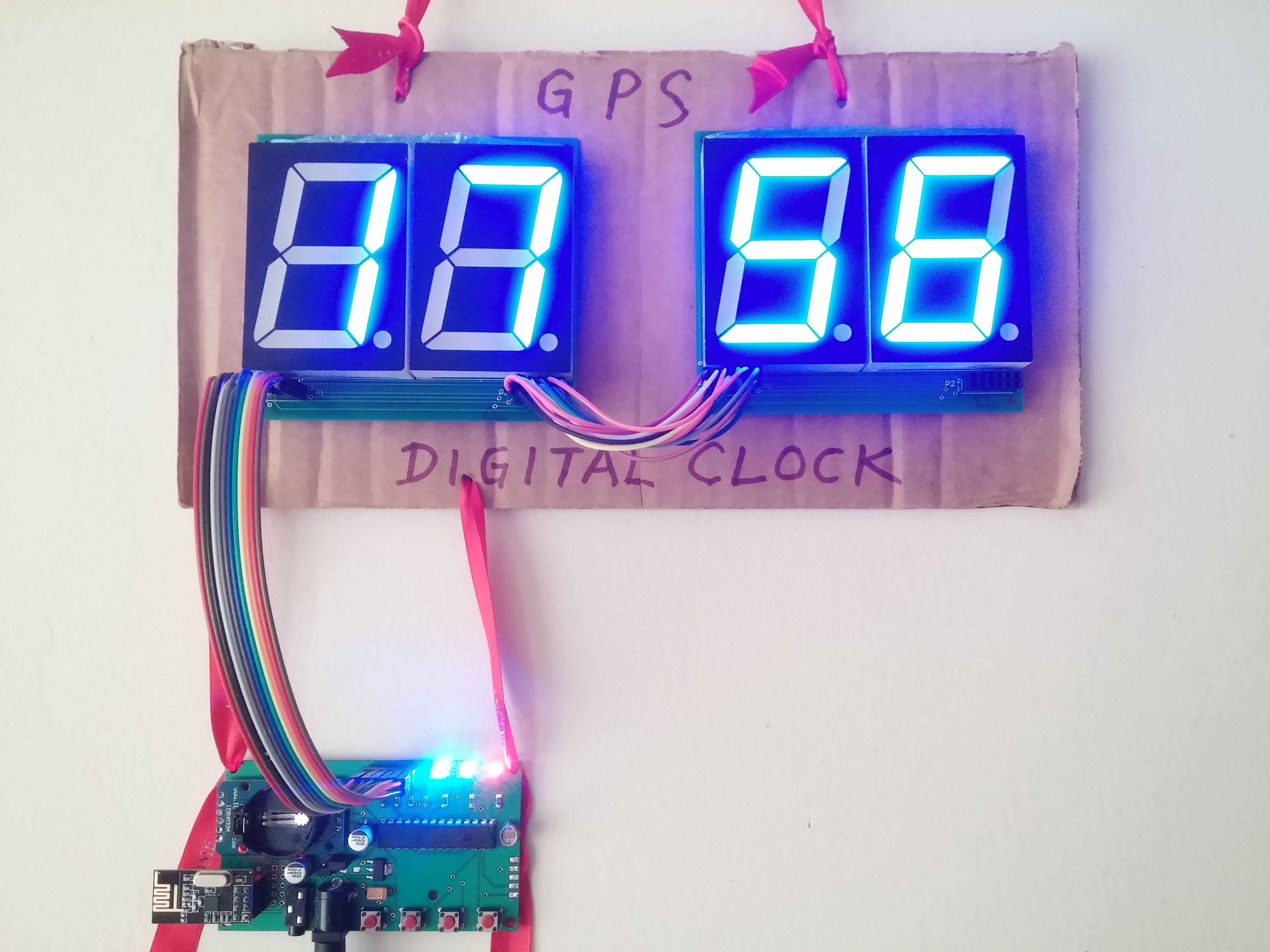
The first version is quite crude in its implementation, but does what its supposed to very well. It is now permanently hung on the bedroom wall with a red string. Wrote "GPS DIGITAL CLOCK" on the backing cardboard just to remind myself what it is...(haha).
Time Calculation
The industry standard NMEA strings that we are used to only provides serial data output (normally at 9600 bps) in GMT time. Malaysian time runs at GMT+8, and clearly some data manipulation is needed here. The easiest solution would be to add 8 hours to all incoming time, with the minutes kept the same. Easy. However, since there is also the calendar that I intended to use, this has to calculate the date, month (and year) to ensure accuracy. Data is obtained by filtering the right data from the GPRMC string.
Since the time is based off valid GPS data, it is obvious that time should only be displayed when there is valid data for calculation. An added benefit of having the RTC on board is that upon obtaining the first valid GPS data, the clock will continue to run from the internal RTC even when the GPS data is no longer available. This is true when I am running the clock over the GPS RF module. The GPS RF module in my living room can be switched off for a few days and the clock in the bedroom will continue to run. Switching on the GPS RF module in the living room after a few days for about 30 mins or so will sync back the bedroom clock.
Ensuring that the clock shows the right time every time, the offset value from GMT is saved in the EEPROM. During startup and initialization, the last stored value of the offset is read from EEPROM into working memory. Upon obtaining a valid GPS time / date, the local time is calculated based on this offset. No batteries needed.
Time Sync
This is technically quite challenging for me as it needs to do several things. However, in general, these are the steps taken.
- Ensure that GPS data is valid (i.e "FIX"). This ensures that the time and date is valid. If it is not valid, ignore.
- Check and calculate the current time / date offset from GMT (determines the current hour and calendar date). Update the RTC with the current time and display on the clock.
- Constantly read and compare the RTC time and live GPS time. If there are differences, update the RTC time.
- If there is no incoming GPS data, continue to run the clock from the internal RTC only. Continuously check for any valid incoming GPS data, and repeat the steps above when there is GPS data again.
Satellite Count
Knowing how many satellites are currently in use the by the GPS module will be much more useful than just the FIX LED indicator. This feature allows the user to place the GPS antenna in the best possible location by finding the spot with the highest number of satellites. Data is obtained by filtering the right data from the GPGGA string.
Other Versions
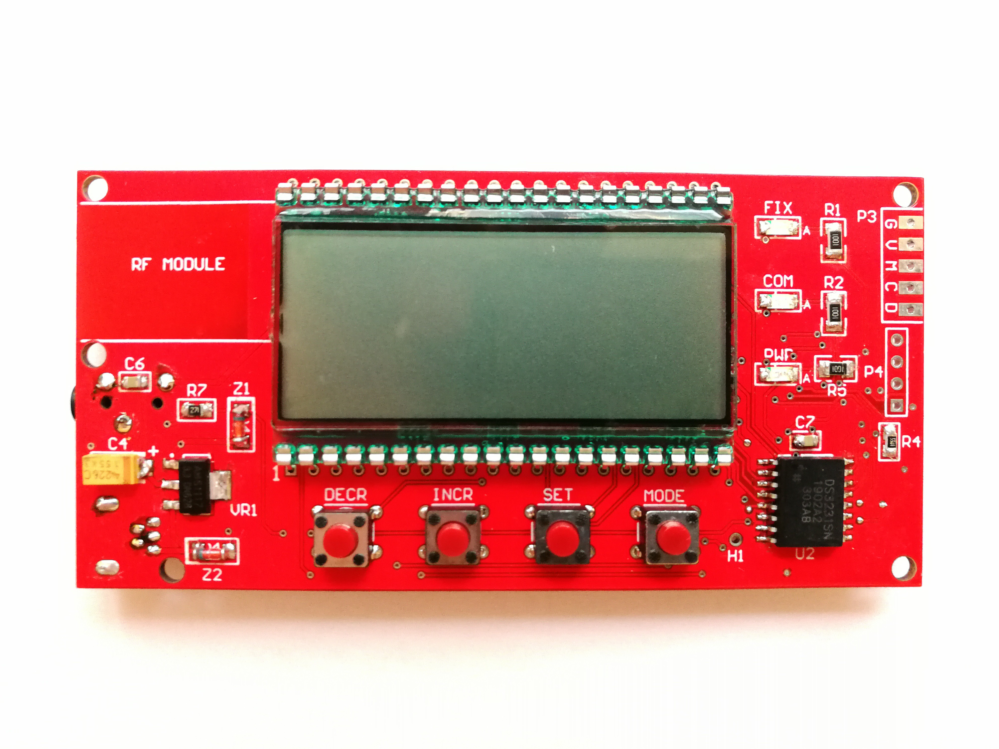
An LCD based version was done for fun just to see how small I could cram all this. It was very time consuming to solder all the SMD parts and only 4 were ever made. Save for the LED dimming features everything else remained quite similar with hardware changes to accommodate the LCD. Runs from 5V very well.
Current Version
A more practical all in one version would have to be the table clock version. This version is sold on Tindie (and other platforms here in Malaysia). The hardware is revised to display only 4 digits HH:MM only. Also, the display size is changed to 1.8 inch 7 segment LEDs and it runs on 5V DC only. It is an integrated clock with the digits mounted on the clock board itself (rather than separately). Also, this board uses an RTC IC (instead of a module like the original version) and more SMD parts. Besides that, additional functions are added:
- 12 / 24 hour time format
- One touch Daylight Saving Time mode (adds 1 hour to the time)
- Automatic selection of GPS input (either via direct connection or via the RF module)
This clock is probably at the maximum of its design limit with the 1.8 inch LED display. Any larger and it cannot be practically powered from 5V DC source (the Vf of the LED display would have exceeded our input voltage of 5V).
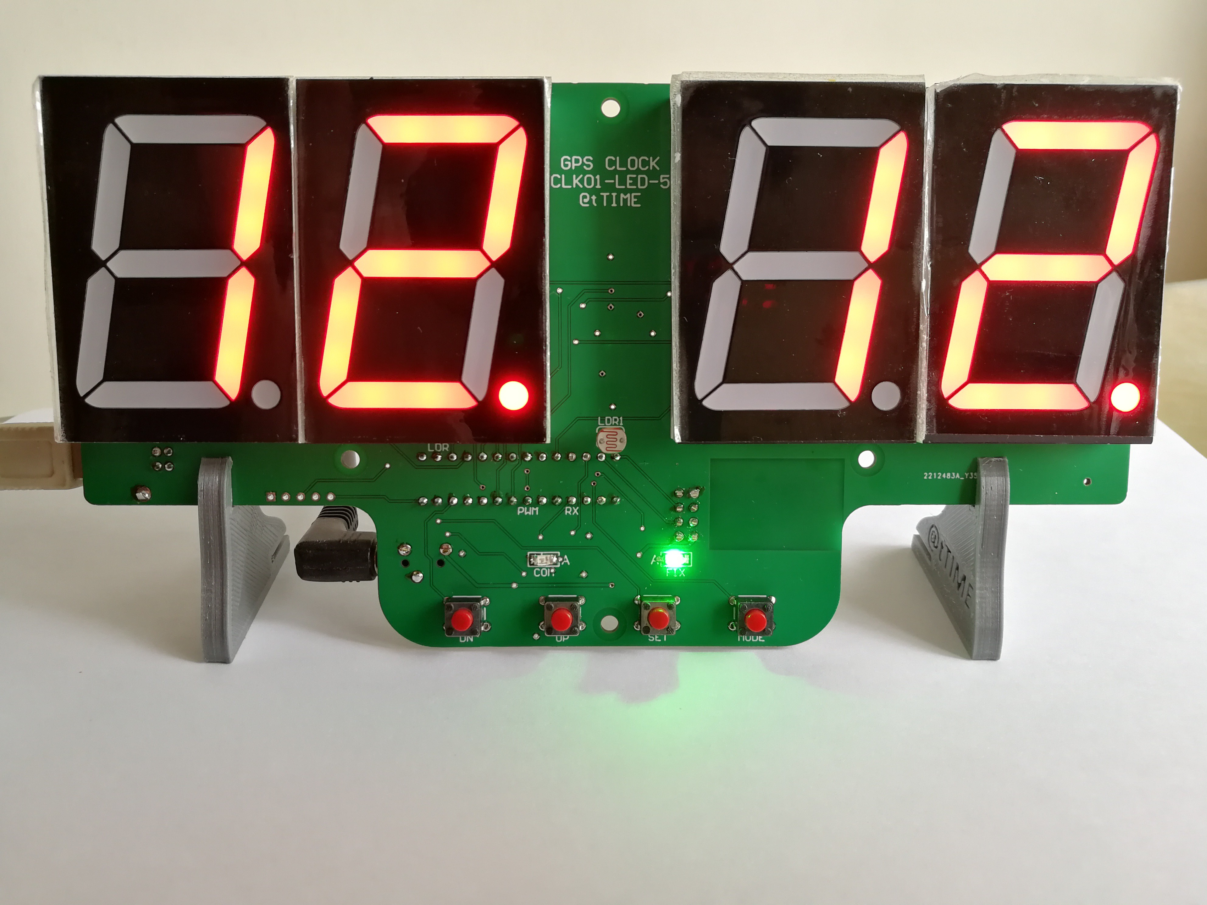
The latest revision suitable for desktop use (can get this in Tindie).
Future Enhancements
There are no further enhancements I can think of to do for this design as of now, except maybe to design some sort of enclosure for the clock. Otherwise, it would be bare PCB with just 3D printed stands.