Sina Roughani
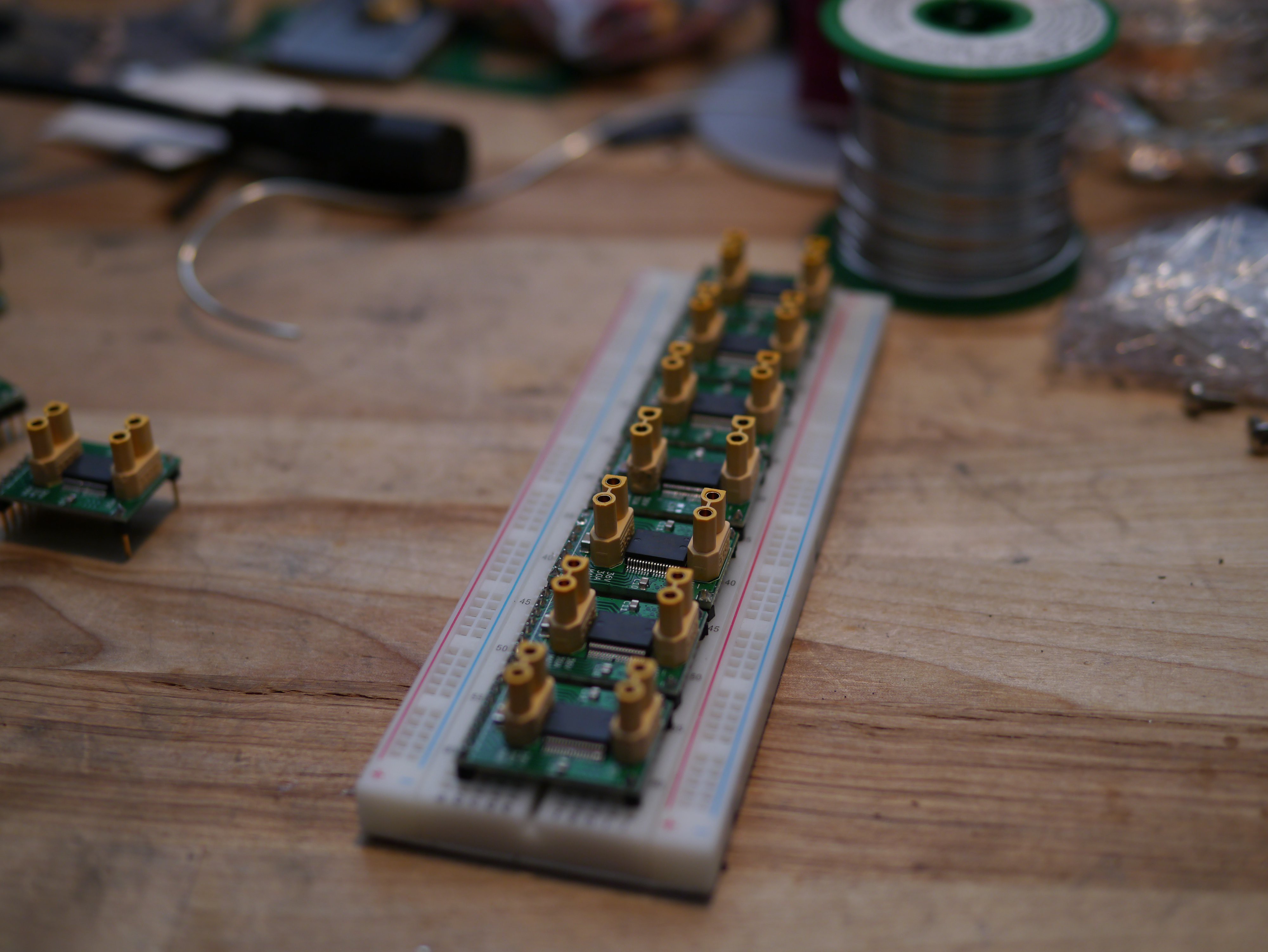
I've used XT30 connectors since I really love the friction fit. I've made the form factor breadboard friendly and compact so that you can maximize your density, but also have one exposed column on the breadboard for your wire connections. I could have added data pin resistors, but on this revision, you need to put resistors at the inputs to protect your MCU.
0%
0%
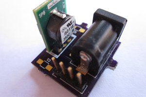
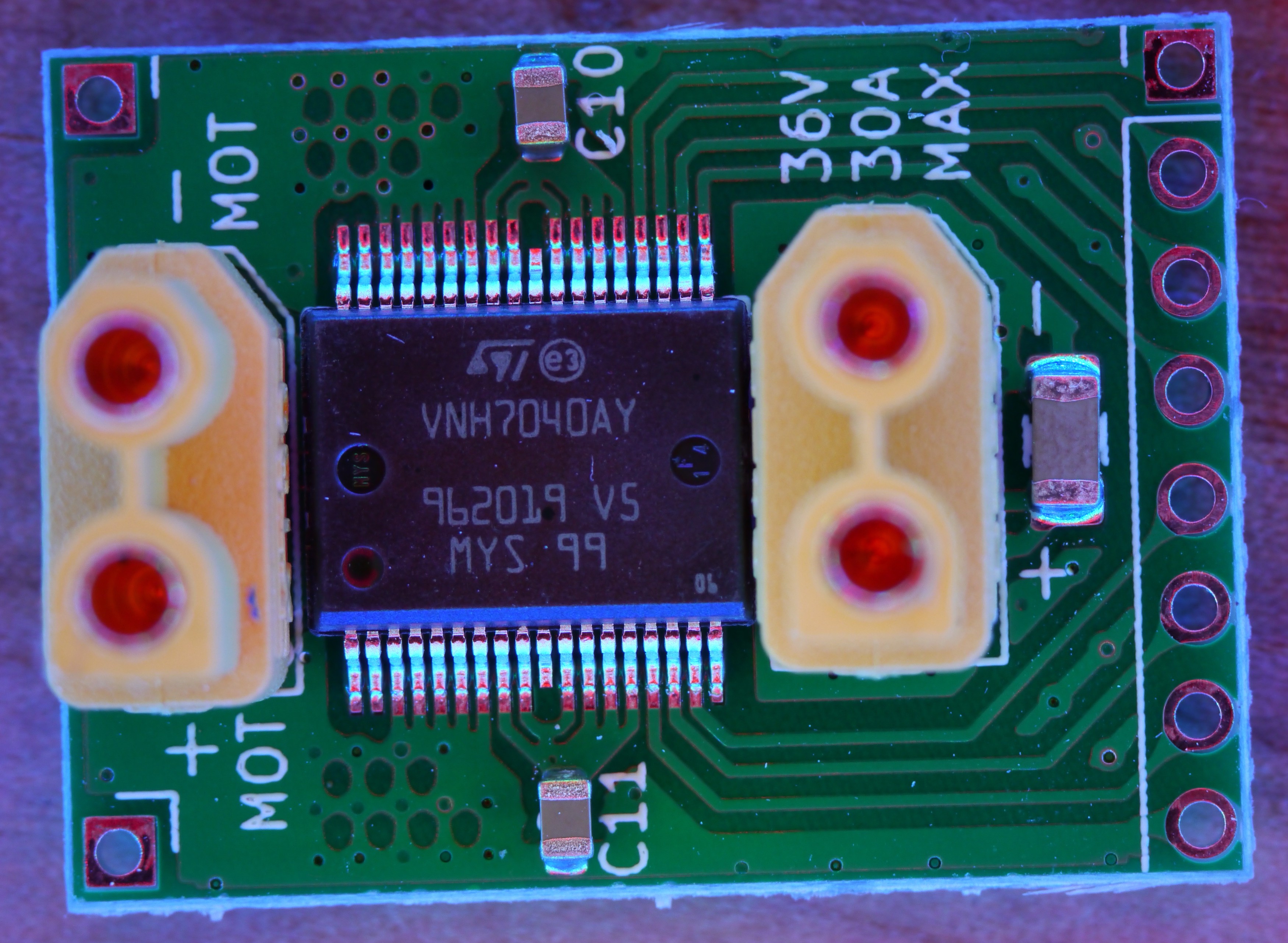
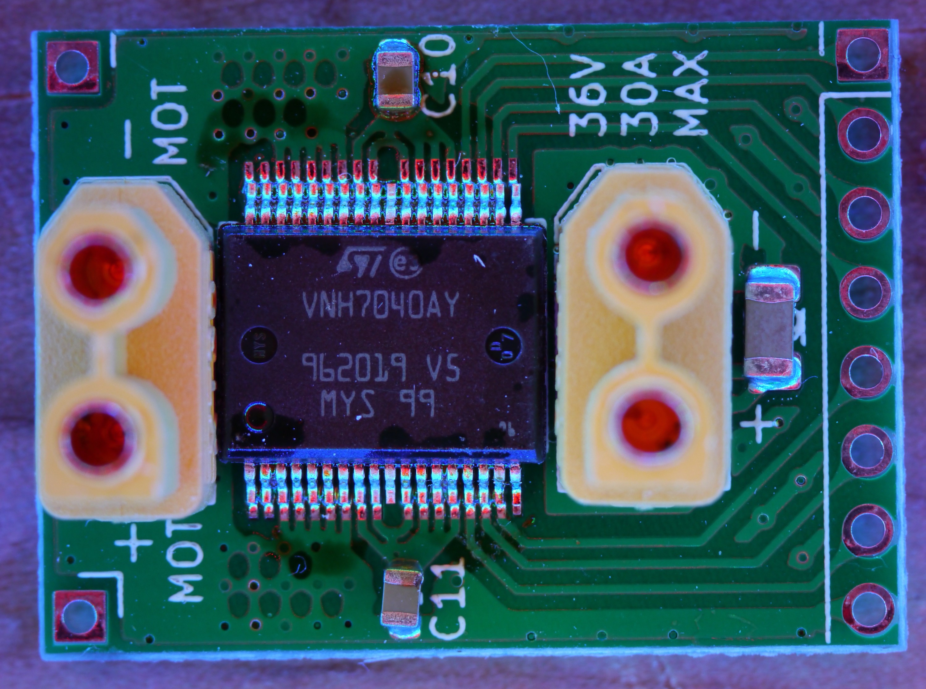
Compact DC Servo Driver
A breadboard friendly VNH7040 breakout board to power all sorts of DC motor related tasks up to 36V and 35A.
Become a Hackaday.io member
Already have an account? Log in.
Just one more thing
To make the experience fit your profile, pick a username and tell us what interests you.
Pick an awesome username
hackaday.io/
Your profile's URL: hackaday.io/username. Max 25 alphanumeric characters.
Pick a few interests
Projects that share your interests
People that share your interests

 bobgreenwade
 Tawez
Tawez