Close
0%
0%

Smarter Micro Servo (SMS) MOD

Hack a micro servo and make it smarter !

Similar projects worth following
This projet is a tiny control board for micro servo. It replaces the original servo control board and provides a smart bus interface (TTL level, Up to 1Mbps) and configurable closed-loop regulation for robotic applications. Any micro and mini servo may be hacked and driven by this board (5-pin interface : 2 for DC motor, 3 for potentiometer). The control board may be directly powered by a LIPo 2S battery (min 6.5V, max 10V).

Commercial off-the-shelf smart 3-pin cables, hubs, accessories and physical interface adapter boards (e.g. TTLinker) may be used to connect the hacked servo to the host controller (Arduino board, Arm-based board, RPi, and Jetson). User can drive up to 254 servo, with the same bus.

Position, velocity, and torque of each servo are controlable. Present voltage, position, velocity, and torque feedback are avaible. Communication protocol is developed for Python and C/C++ Arduino. Ping, read, write, sync write, reboot, factory reset commands are supported.

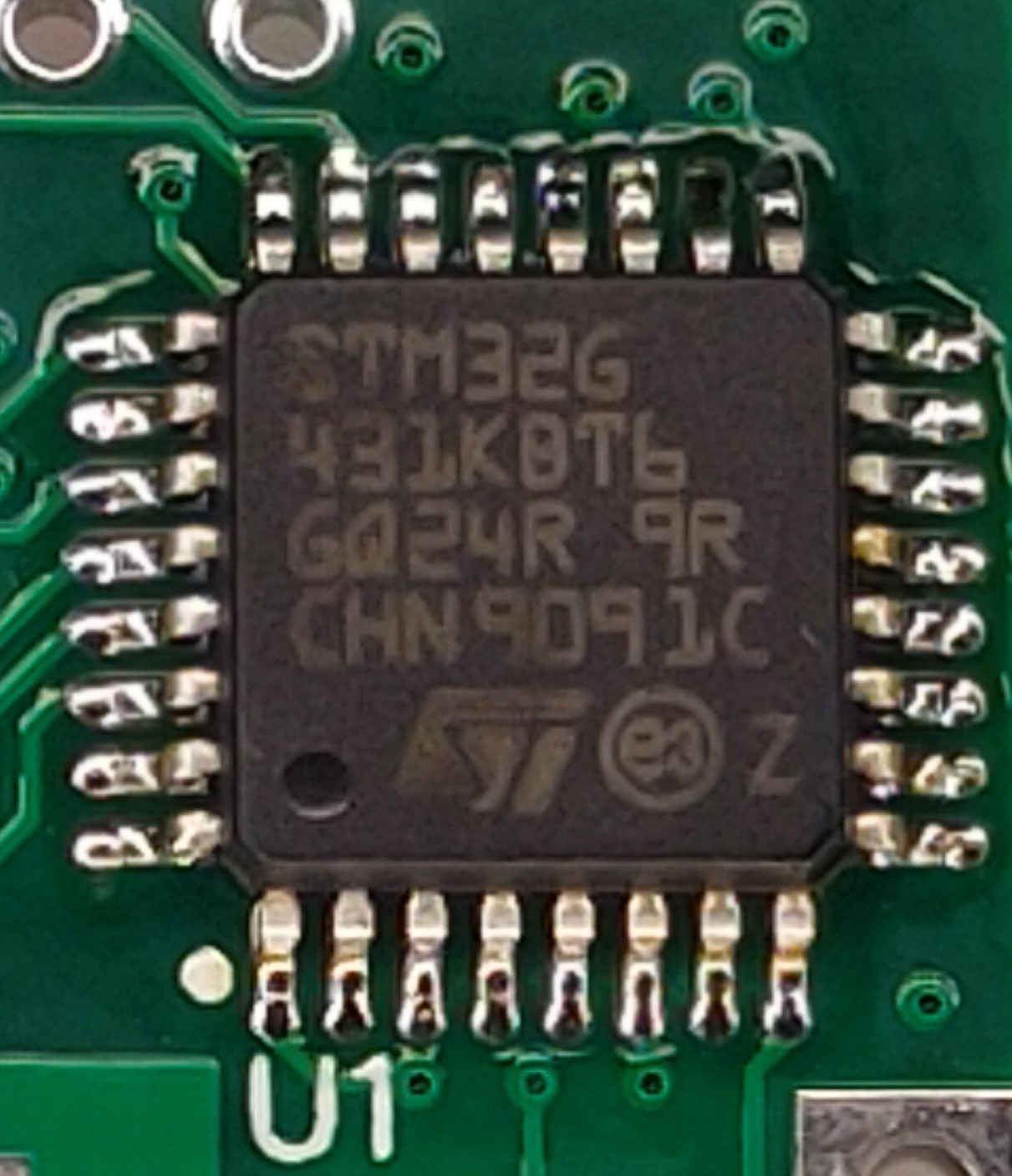
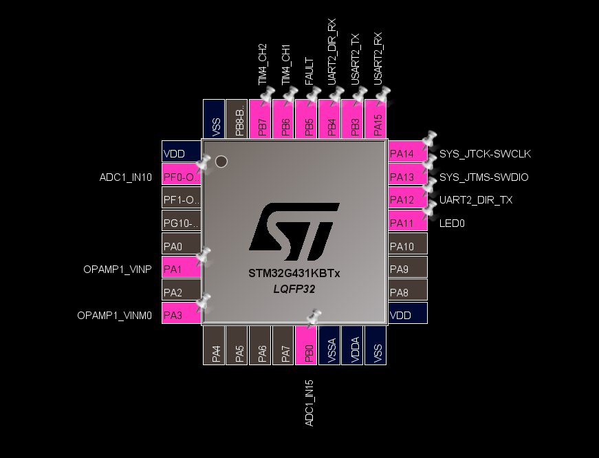
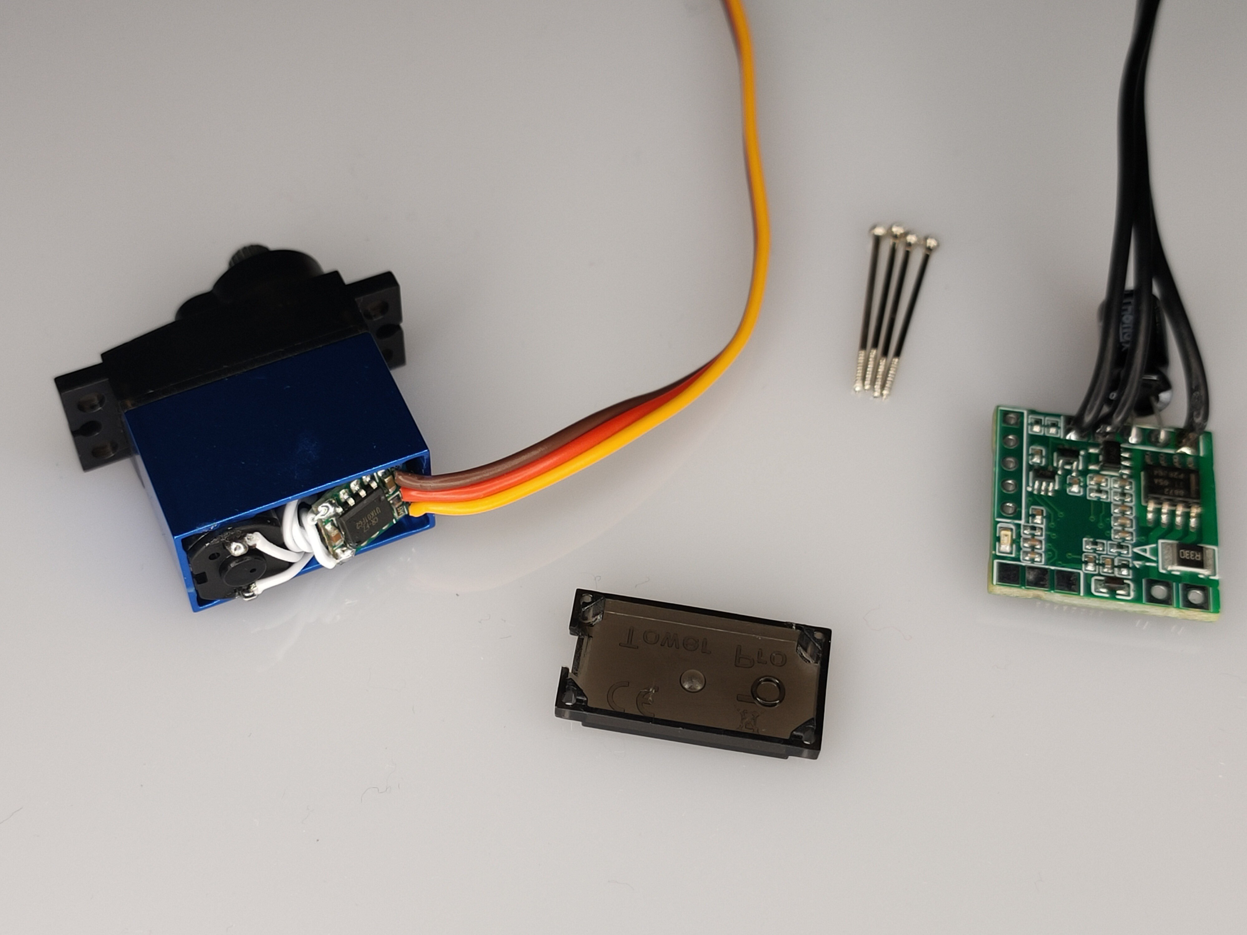
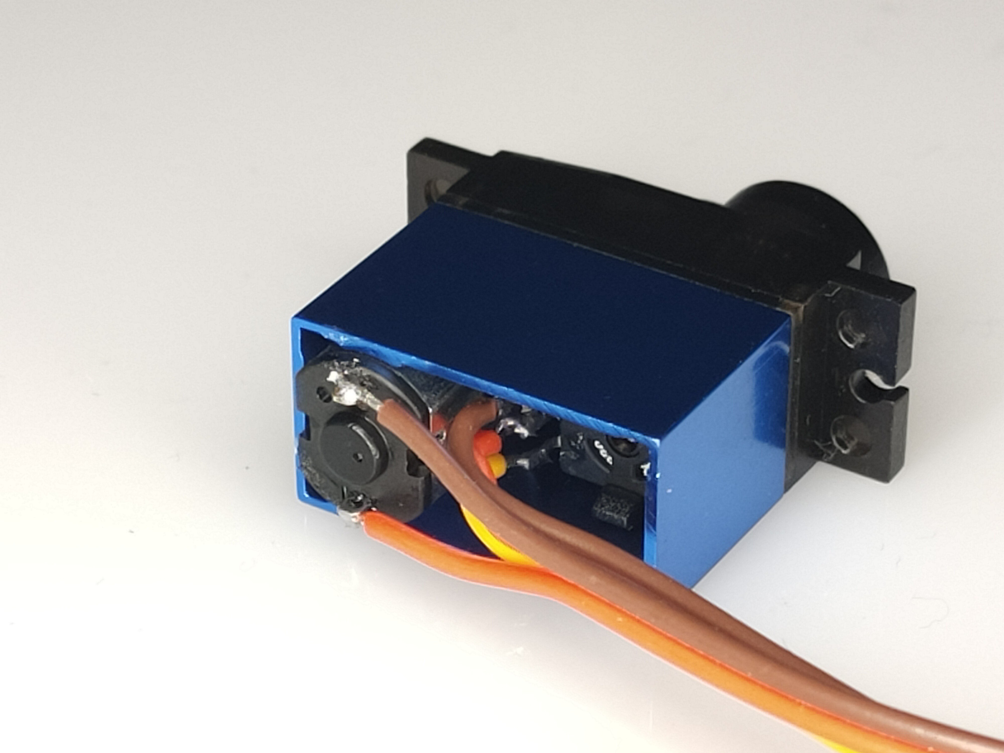
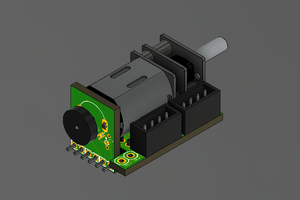
The SMS controller board is a 4-layer tiny 20x20mm PCB, that features a STM32G431KB, based on a Arm Cortex-M4 32-bit RISC core operating at 150 MHz.

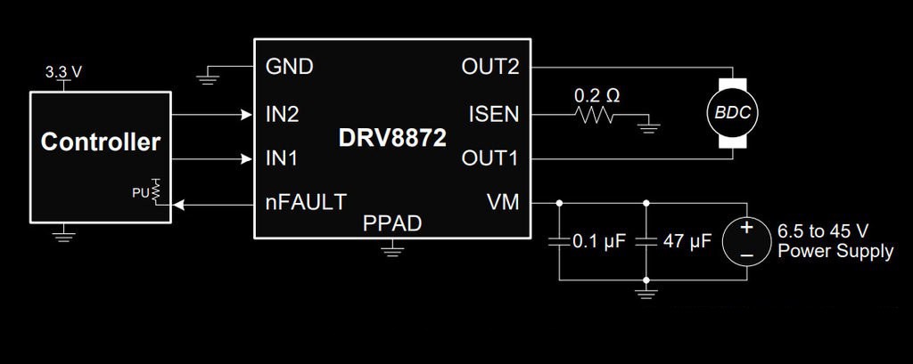
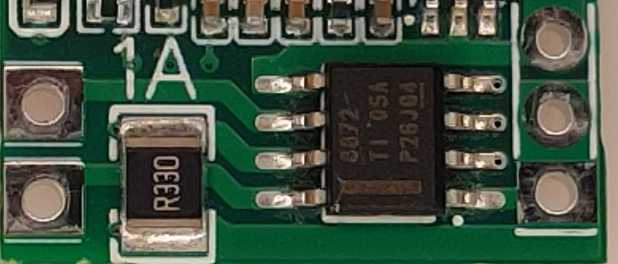
The SMS controller board also features a Ti DRV8872 3.6-A H-bridge motor driver with fault reporting & current regulation, a shunt resistor (Rsense) and a large bulk capacitor on power supply input.

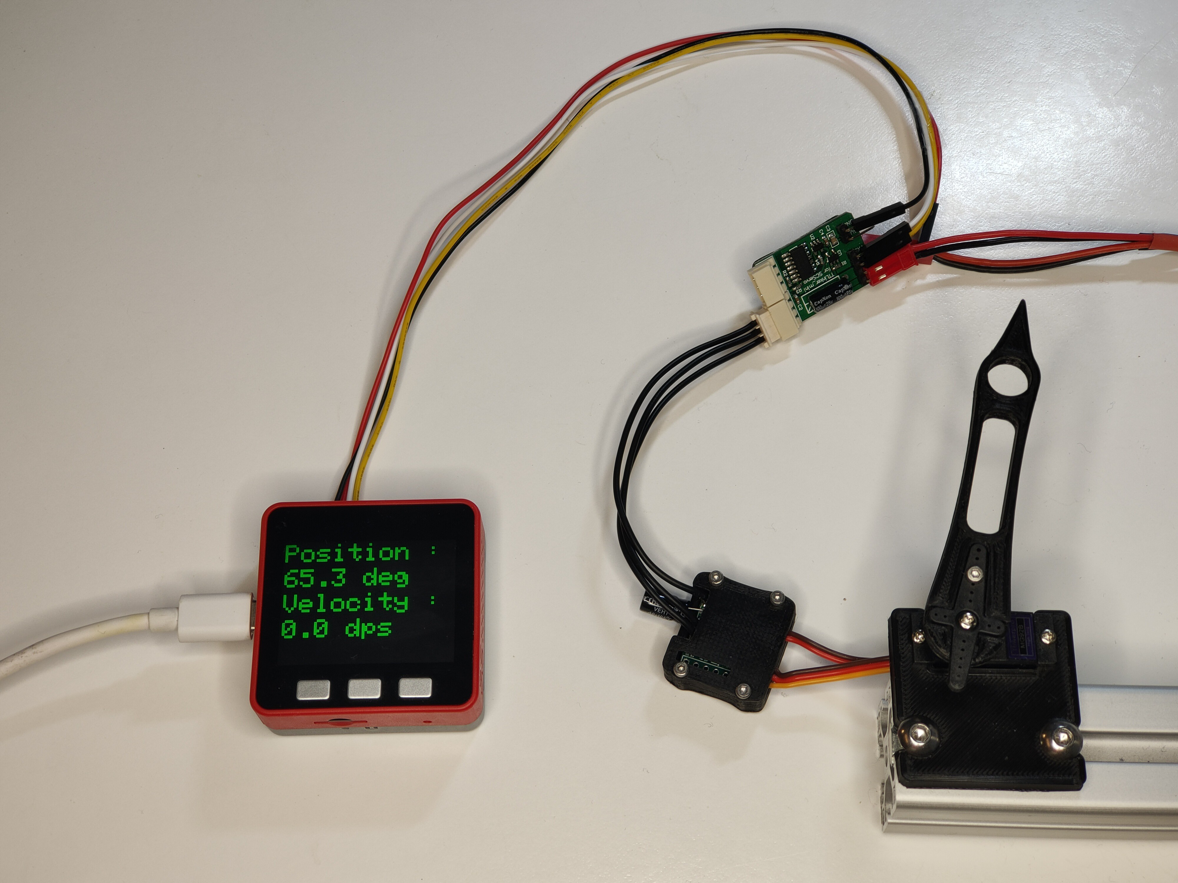
The SMS board is compatible with any micro and mini servo based on a DC brushed motor (2 leads) and an absolute position sensor based on a potentiometer (3 leads).  The position is acquired by the STM32 with a precision of 12 bits (ADC) and the positionnal resolution is less than 1°. 

The DRV8872 device is used in the "PWM With Current Regulation" mode. The maximum motor current is set to 1A. The maximum ouput current depends on R1, the shunt resistor, which is 0.33R. This shunt resistor is also used to measure the motor current in FORWARD and REVERSE drive modes (unipolar current sensing). The signal comming from the sense resistor is amplified and sampled by the STM32 with a precision of 12-bits (built-in OP-AMP PGA gain=8 and ADC).

The frequency of motor PWM is set to 20KHz. Servo position, motor current and battery voltage are sampled at 20KHz. The control algorithm (PID) executed by the STM32 firmware is clocked at 1KHz.

The SMS board offers different control algorithms, selectable and parametrable by user :

  • Position control mode
  • Current-based position control mode (default mode)
  • Current-based position control mode with velocity/acceleration profil (most advanced)
  • Current control mode
  • Direct motor PWM control mode

The SMS board does not offer a velocity control mode because the potentiometer, used as position and velocity sensor, cannot handle multiple turns.

The current-based position control mode (with and w/o profil) use a position PID and a current PI.  The goal position is the setpoint for the first PID. The output of the first PID is the setpoint of the second PI. This control loop allow position compliance. This operating mode is designed for legged robot, with fast servo moves and high goal position refresh rate.

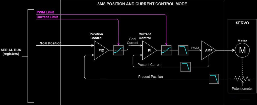
The profil takes in account velocity and acceleration limits, and provides real time position, velocity and acceleration setpoints to the position PID with feed forwards. This operating mode is desgined for robot arm for smotth and precise positionning, avoiding vibrations and jerk.

The STM32 firmware is built using STM32CubeIDE. Serial communication is handled by the UART2 and DMA. Motor PWM signals are generated by the TIM4 (two channels). Position, current and voltage are sampled using ADC1 and DMA, when TIM4 ouputs trigger update event. LED is driven by a GPIO (output). DRV8872 fault signal is monitored by a GPIO (input) too.

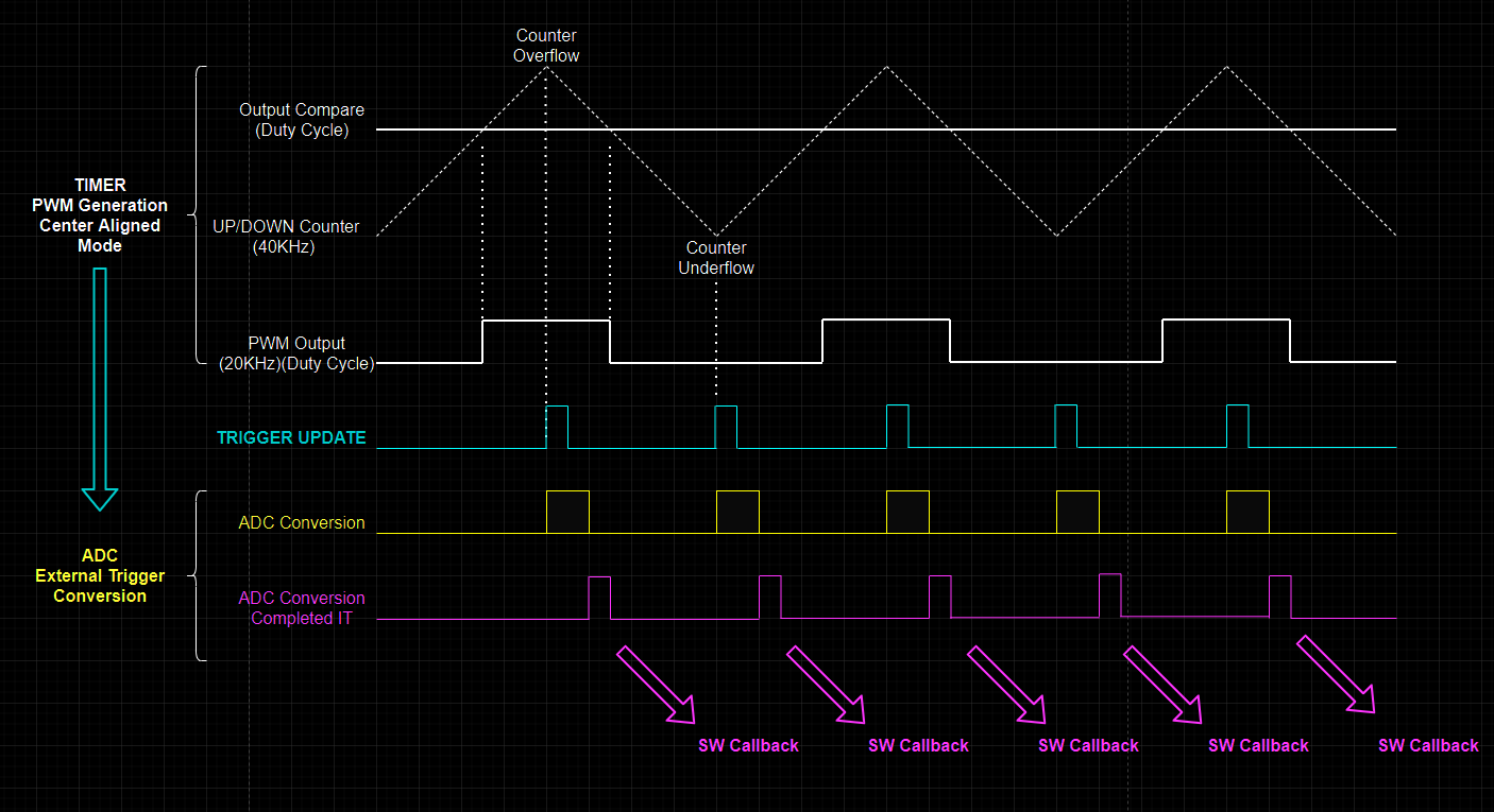
Average motor current is estimated using only one ADC sample per motor PWM period.

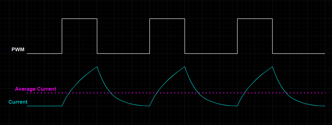
In order to measure motor current during PWM pulse, the TIMER4 is configured in the mode "PWM generation center-aligned", with a trigger ouput event on counter update. The ADC is configured to start conversion on TIMER4 trigger event (rising edge). ADC samples motor current, servo position and battery voltage in a 3-stage scan. A DMA is configred to transfer conversion from peripheral to memory in a target circular buffer. The completed conversion interupt is catched by software. Samples are filtered and scaled according calibration parameters.

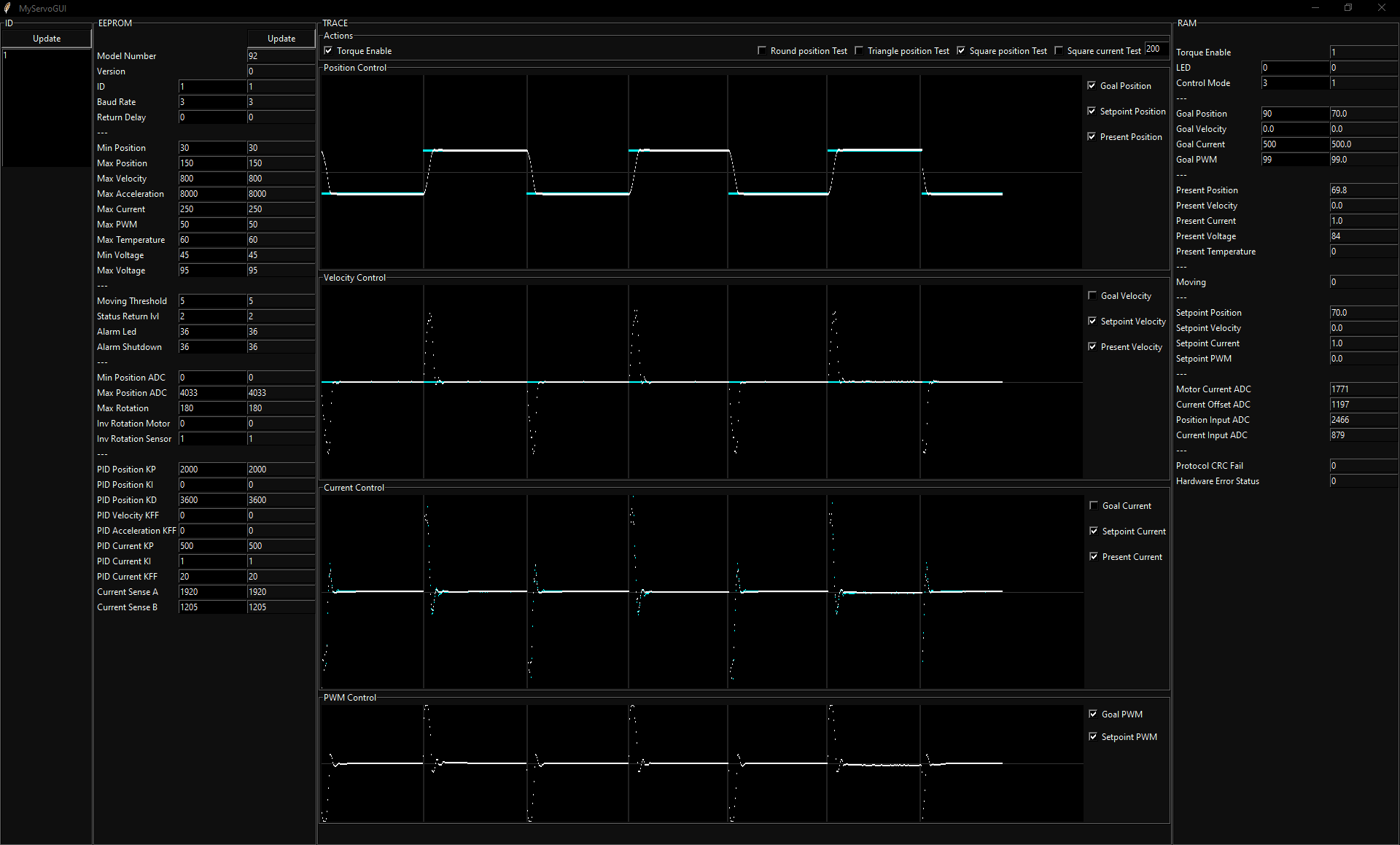
A python script for PC allows configuration and monitoring of SMS controller board.

Arduino example sketchs are also provided.

Main forum thread (Fr) : Robot Maker Forum

Development processus (Videos) : MG90s hack playlist

Examples (Videos) : SMS Controller Board

Adobe Portable Document Format - 121.90 kB - 01/08/2021 at 14:32

Preview
Download

ms-excel - 3.86 kB - 01/05/2021 at 07:41

Download

Portable Network Graphics (PNG) - 83.23 kB - 01/05/2021 at 07:40

Preview
Download

SMS control table.xlsx

EEPROM and RAM registers

sheet - 15.47 kB - 01/08/2021 at 14:31

Download

  • 1 × STM32G431 Microcontroller ARM Cortex M4 32 bits 150MHz
  • 1 × DRV8872 DC Brushed Motor controller 3.6A

  • Haptic demonstration

    pat92fr01/23/2021 at 14:20 0 comments

    Hello, 

    This is the latest use case of the SMS board with two MG92b low cost servo.

    The Arduino M5StickC Plus captures "present position" of both servo, computes the average position and sends it as "goal position" to both servo, in order to produce the haptic effect. Due to the high gear ratio of R/C servo, the effect is not as impressive as low ratio high power brushless servo, but it is working quite well. For this demo, I have just lowered the Kp of the PID position (one of the EEPROM settings) handled by the SMS board. On the right, you can see the power consumption of both servo in mA. The power voltage is set to 8V (intended to be powered by 2s Lipo battery at the end).

    Bye. Patrick.

  • Design shrinking

    pat92fr01/05/2021 at 07:55 0 comments

    Hello ! The next step will be probably shrinking the control board. I am looking for a PCBA that can build such a small PCB and assemble it in small quantity. The first revision of PCB has been assembled by JLCPCB (PCB & SMT Assembly services).

View all 2 project logs

  • 1
    Hacking a MG92b : Open the servo

    Remove the cover that has the 4 screws, exposing the motor and PCB.

  • 2
    Hacking a MG92b : Remove PCB

    Unsolder all wires and remove genuine PCB

  • 3
    Hacking a MG92b : Wiring the servo

    Re-use the servo wires and solder 2 short wires on the motor, 3 short wires on the potentiometer.

View all 5 instructions

Enjoy this project?

Share

Discussions

agarner3 wrote 04/08/2024 at 06:41 point

hey @pat92fr, just curious if there where any updates to this project? I would love a smaller form factor. Is there a reason the positive and negative supply wires are seperate for the POT and motor?

  Are you sure? yes | no

55222091 wrote 07/08/2023 at 04:56 point

Hello, read your share, I would like to learn, may I ask what programming software you use for firmware programming?

  Are you sure? yes | no

Anthrobotics wrote 01/11/2021 at 03:50 point

This definitely has potential for use in compliant robot drives! The nice thing is that a lot of these hobby servos are pretty affordable, and combined with this board, it's almost like an ODrive but for servos. Awesome work, we'll be following this closely!

  Are you sure? yes | no

pat92fr wrote 01/12/2021 at 21:44 point

Thank you very much for your comment! You have fully understood the interest of this project. I hope it will be useful to (robot) makers.

  Are you sure? yes | no

pat92fr wrote 01/05/2021 at 07:57 point

Any comment for a better smarter micro servo, is welcome. Thank you.

  Are you sure? yes | no

Similar Projects

Does this project spark your interest?

Become a member to follow this project and never miss any updates