 Jesús Tamez-Duque
Alice addresses manufacturing, material and cost restrictions specifically encountered in Latin America and other developing countries, promoting successful exoskeleton deployment within budget-restricted communities.
Furthermore, the exoskeleton proposes a specialized combination of hardware, software and operation conditions focused on reducing complexity while achieving the minimum required functionality for previously-unattended patients.
Her Clinical Validation
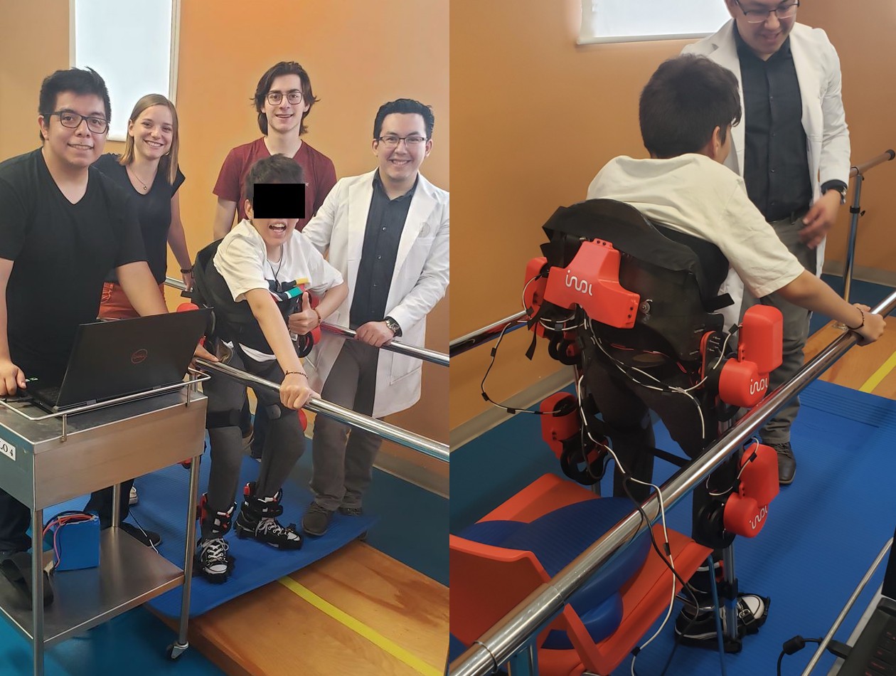
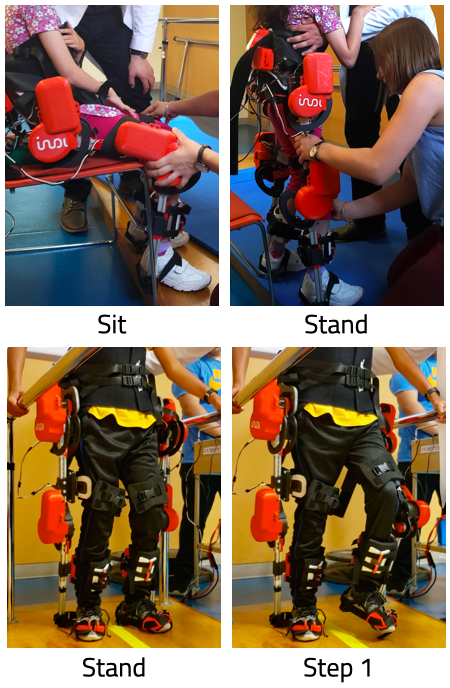
ALICE has successfully been deployed with patients exhibiting different medical conditions and covering a diversity of socio-economic backgrounds primarily in Monterrey, México.
A total of 12 pediatric subjects have participated in short-term clinical usage which has proved beneficial in improving patient psychology as well as due to potential positive impacts in blood circulation and internal organ functioning.
Conditions exhibited by users included Muscular Dystrophy (MD), Cerebral Palsy (CP), Spinal Muscular Atrophy (SMA), and Cephalic Disorder (CD).
Mechanics:
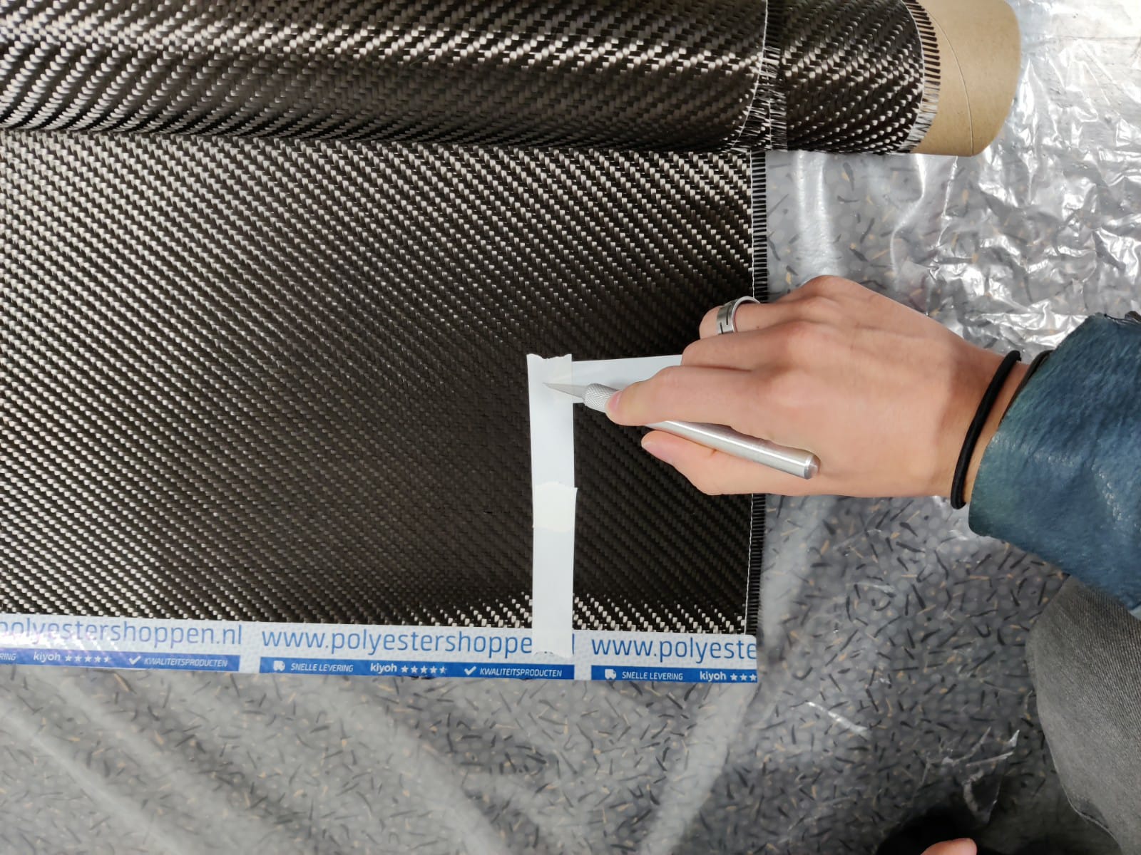
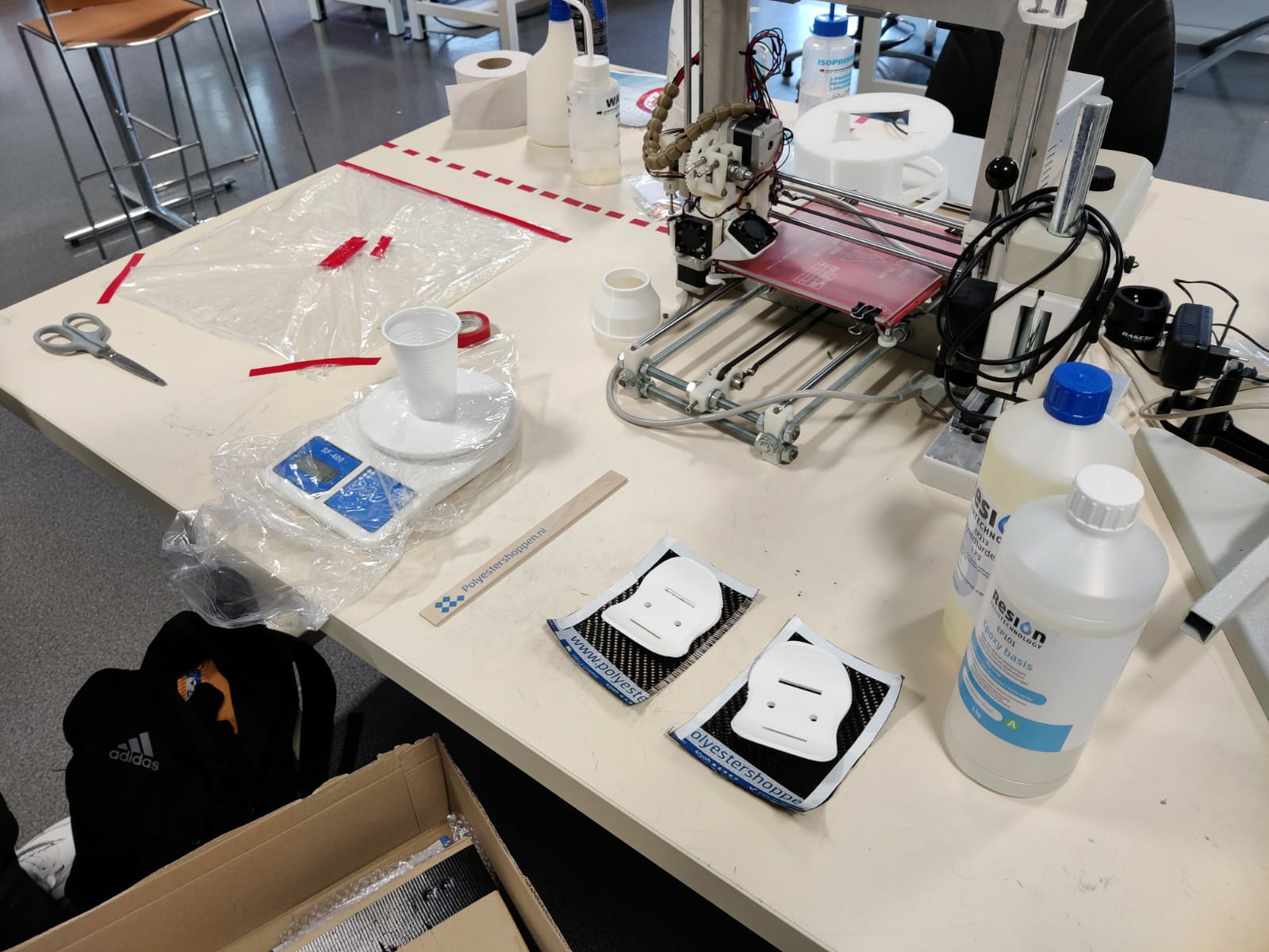
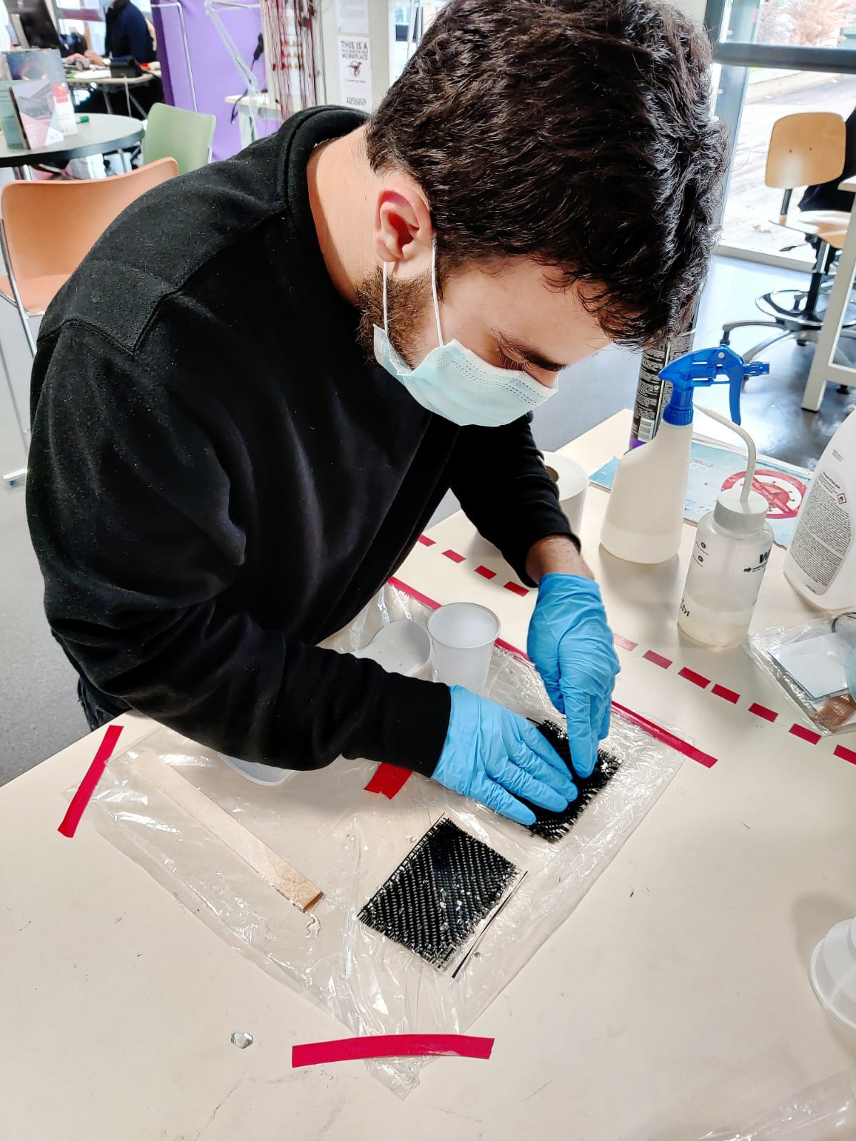
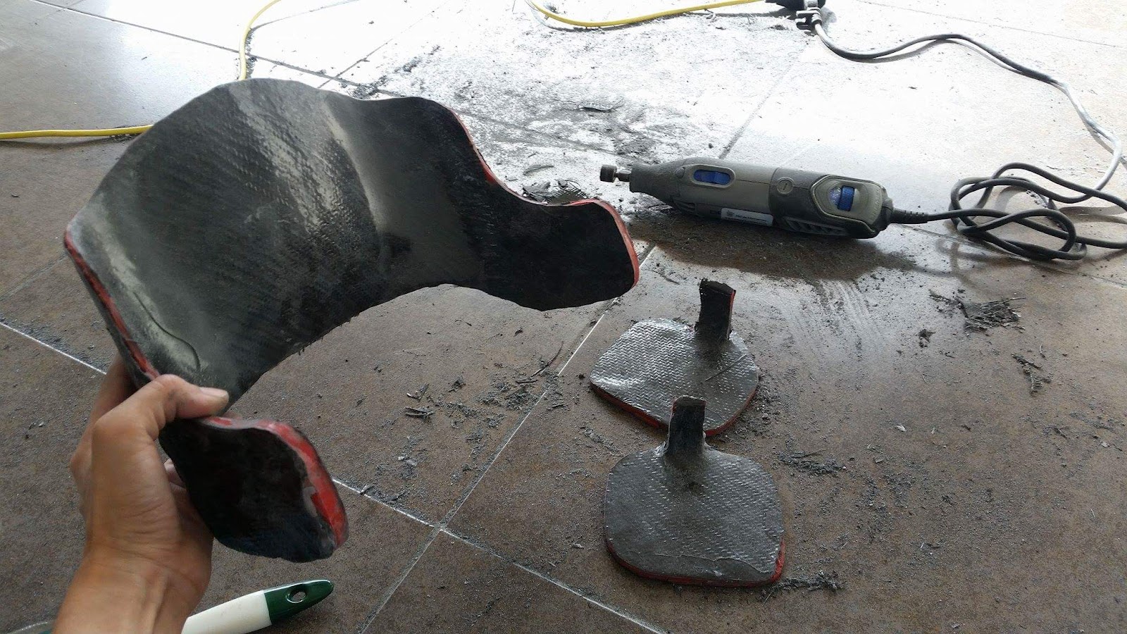
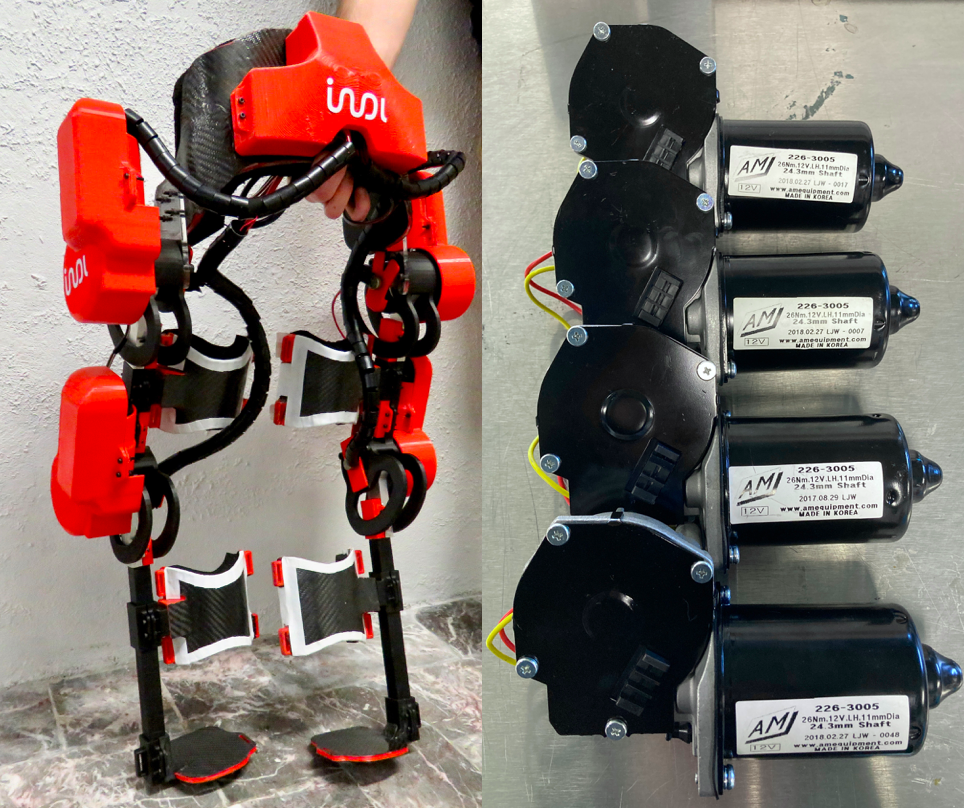
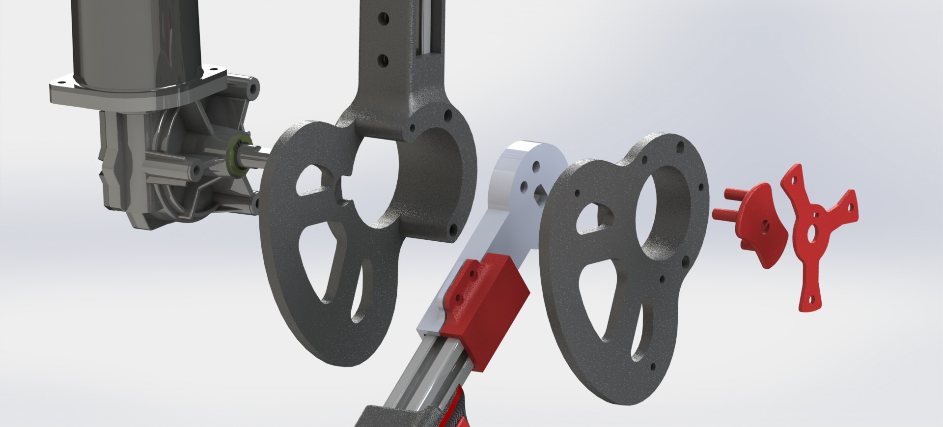
The system features only 4 DOFs powered by automotive DC 26Nm actuators as well as a significant portion of parts manufactured on PLA and commercial 3D-Printing composites.
Programming:
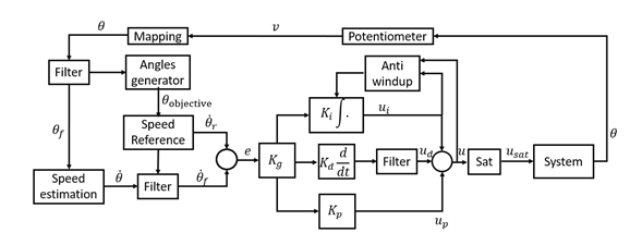
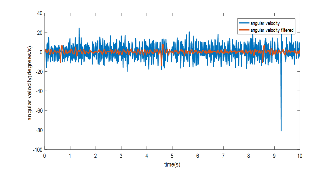
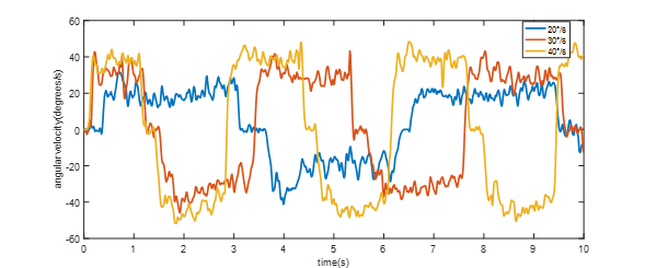
Motion is achieved through simplified PID controllers designed and implemented over low-cost electronics and in conjunction with non-specialized actuators + basic potentiometer-based feedback. Controllers are designed to counter actuator nonlinearities through customized filtering, anti-windup algorithms, and static friction compensations.
Operation Layout:
ALICE operates using a decentralized layout where the power source and system operation modules are separated from the exoskeleton. Standard automotive 12V Lithium / Lead batteries and a PC or Mac running Arduino IDE are enough to successfully operate the exoskeleton in safety-compliant clinical contexts.
Patents:
1. (2019, China) CN201930193288.2 Electromechanical Structure for Pediatric Mobility.
2. (2019, México) MX/f/2019/000922 Estructura electromecánica para movilidad pediátrica.
A basic model of ALICE can be constructed with a material budget of ~1,500 EUR.


 Vaibhav Chhabra
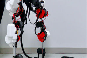
 Michael Graham
Hi. Good Morning. congratulations for the great job. could you provide the stl case of the engines. please.