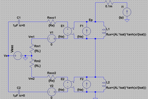
• First prototype build

    Richard Dudley01/06/2021 at 04:48 0 comments

    I figured that building the DACs into stacks would be the simplest and quickest way to get a prototype up and running. The PCB I based this on already had 4 sites for TDA1387s so I piled 5 DAC chips on each site. Rather than connecting all the DAC outputs in parallel I pass each through a 2N7002 arranged as a common-gate (or cascode) stage and only then parallel the outputs from the 2N7002s. The G-S voltage in the current range of interest is ~2V for this FET so I began with a 3V zener feeding the gates to give ~1V at the DAC output.

    Each DAC output is a current source, (i.e. current is fed from the DAC's positive supply pin) to get current to flow into the source of the FET I needed a biassing current source. This in effect creates what's called a 'folded cascode' configuration.

    The first prototype oscillated like crazy around 40MHz when I first powered up. The problem was in my haste to get a working circuit I omitted some important components - gate stopping resistors. The cascode stage seems to need mitigation of oscillation - a 510R resistor in series with each gate does the trick. The 3V zener also needs a bit more current than is normal for zeners to get to its advertized voltage, so its given around 7mA bias.