 mbsg99
Water Level Detection Module article is being published in collaboration with JLCPCB. It is one of the most experienced PCB manufacturers in China with more than a decade in the field of PCB prototype and fabrication, they are committed to meeting the needs of our customers from different industries in terms of quality, delivery, cost-effectiveness and any other demanding requests.
Introduction
Water tank surge is a big occurrence that leads to water wastage. Although there are many solutions to this like ball valves that automatically stop the flow of water once the tank is filled. So here's a quick and useful DIY that will direct you on making a circuit that senses the water level and raises an alarm when you get the water tank full or a preset level.
This simple water level indicator circuit based on transistors is very useful for indicating the water levels in a tank. Whenever tank is filled we receive alerts at specific levels. We've created 4 levels here (low, medium, strong, and full), so we can build alarms for more. We've inserted 3 LEDs to indicate three initial levels (A, B, C) and one Buzzer to signify Total (D).
Components Required:
- 4 - BC547 transistors
- 6 - 220 ohm resistors
- 3 - Colour LEDs - red, green, and yellow
- 1 – Buzzer
- 9V battery and Barrel Jack

Schematics

Project Description
When the water level reaches point A, the circuit is completed with RED LED & transistor Q1, and the RED LED glows. Likewise when the water level reaches point B, the YELLOW LED and transistor Q2 circuit is completed and the Yellow LED glows, so does point C. And then when the tank gets full (Point D), the circuit with buzzer is done and the buzzer begins to beep.
BC-547 Transistor
The BC547 transistor is an NPN transistor. A transistor is nothing but the transfer of resistance which is used for amplifying the current. A small current of the base terminal of this transistor will control the large current of emitter and base terminals. The main function of this transistor is to amplify as well as switching purposes. The maximum gain current of this transistor is 800A.
· Pin1 (Collector): This pin is denoted with symbol ‘C’ and the flow of current will be through the collector terminal.
· Pin2 (Base): This pin controls the transistor biasing.
· Pin3 (Emitter): The current supplies out through emitter terminal
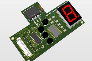
PCB Design

3D model (Top View)

Find All the above hardware components as follows:
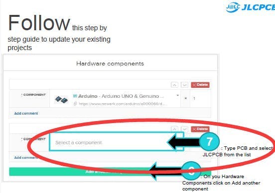
Ordering the PCBs From JLCPCB

Full Process is shown using Screenshots Step-wise
Now we have got the PCB design and it’s time to order the PCB’s. For that, you just have to go to JLCPCB.com, and click on “QUOTE NOW” button.
JLCPCB are also sponsor of this project. JLCPCB (ShenzhenJLC Electronics Co., Ltd.), is the largest PCB prototype enterprise in China and a high-tech manufacturer specializing in quick PCB prototype and small-batch PCB production. You can order a minimum of 5 PCBs for just $2.
To get the PCB manufactured, upload the gerber file you downloaded in the last step. Upload the.zip file or you can also drag and drop the gerber files.
After uploading the zip file, you’ll see a success message at the bottom if the file is successfully uploaded.
You can review the PCB in the Gerber viewer to make sure everything is good. You can view both top and bottom of the PCB. After making sure our PCB looks good, we can now place the order at a reasonable price. You can order 5 PCBs for just $2 but if it’s your first order then you can get 5 PCBs for $2.
To place the order, click on “SAVE TO CART” button. My PCBs took 2 days to get manufactured and arrived within a week using DHL delivery option. PCBs were well packed and the quality was really good.
 Arshmah Shahkar
 electronicsworkshops
 CustomElectronics
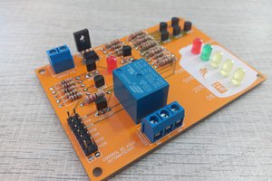
 ElectronicABC