 Vedant Paranjape
I was always amazed at these small devices. My dad uses these to log into his work laptop, I couldn't understand how can it generate a code without being connected to any network.
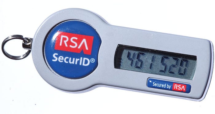
I fired up google and tried to search about it, and surprisingly it used a pretty amazing concept. It had a shared key with the server and then it did some computation on the shared key and current UTC time to get a 6-digit number. So, the remote device just had to be accurate at timekeeping. It uses a algorithm called TOTP (Time based one time password), it's been standardized and there's no point in getting into the details, here's the standard if anyone wants to take a look. You can read this article on freecodecamp.org for more layman-ish approach to the whole algorithm.
First Prototype
Coming back, so I decided to implement this using ESP32, because I had a devkit lying around, and the OLED and RTC libraries were solid, and I could use WiFi to get accurate time, which is absolutely need to generate the codes, here's a picture of the first prototype.
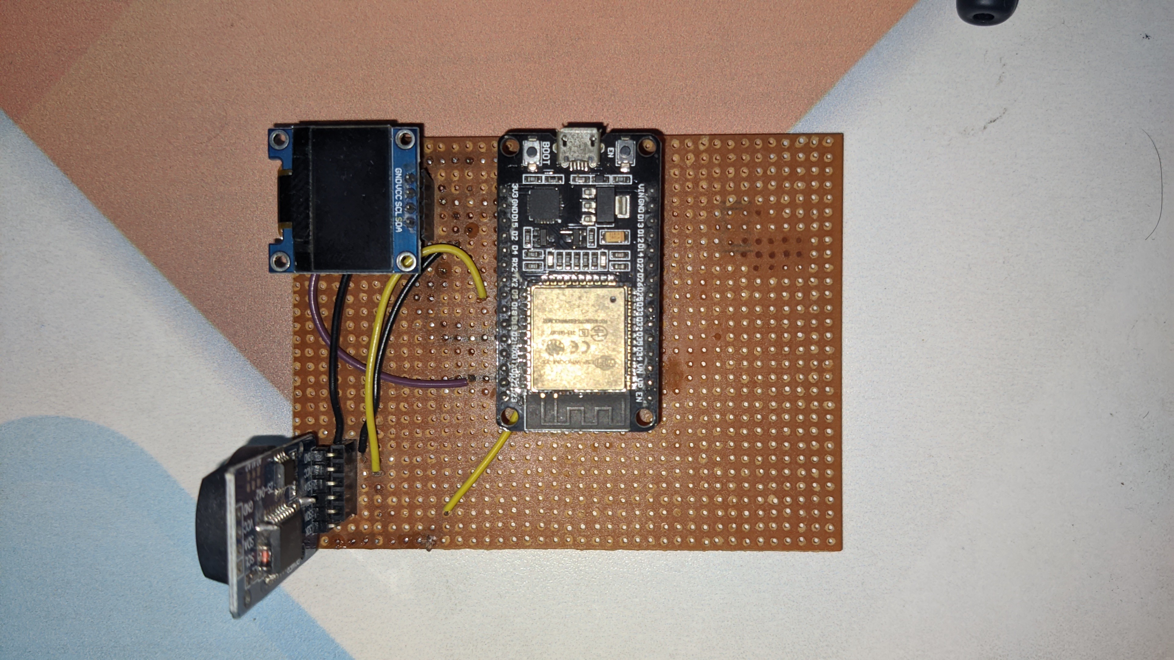
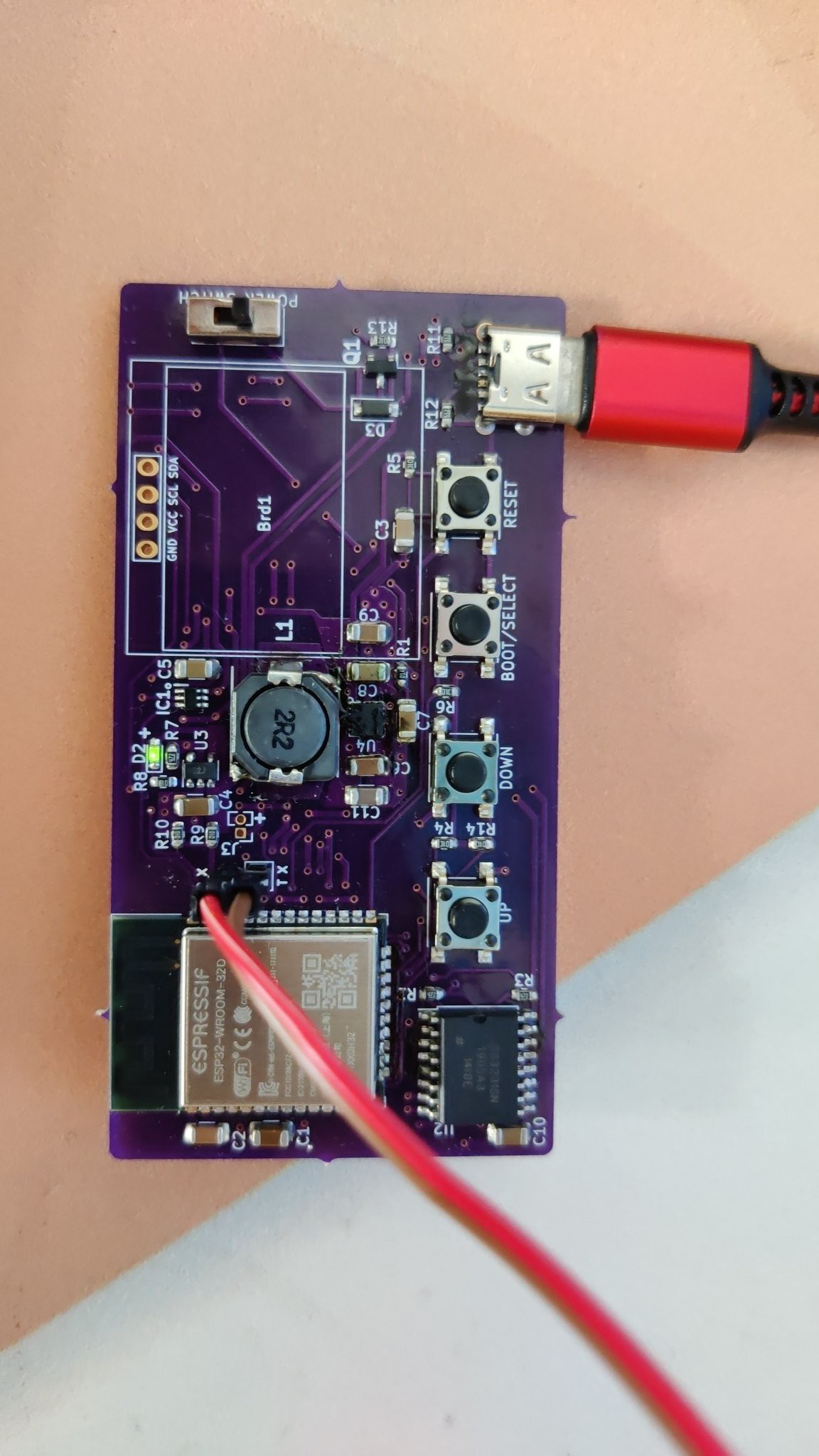
It worked fine, I used to generate a secret key from here, and then flash the esp32 with the new key and boom, it generated codes I wanted to (It was not as easy as it sounds, I had to spend days putting together a firmware to do it, and it was start of Covid-19 Lock down so I had a lot of free time).
Second Prototype
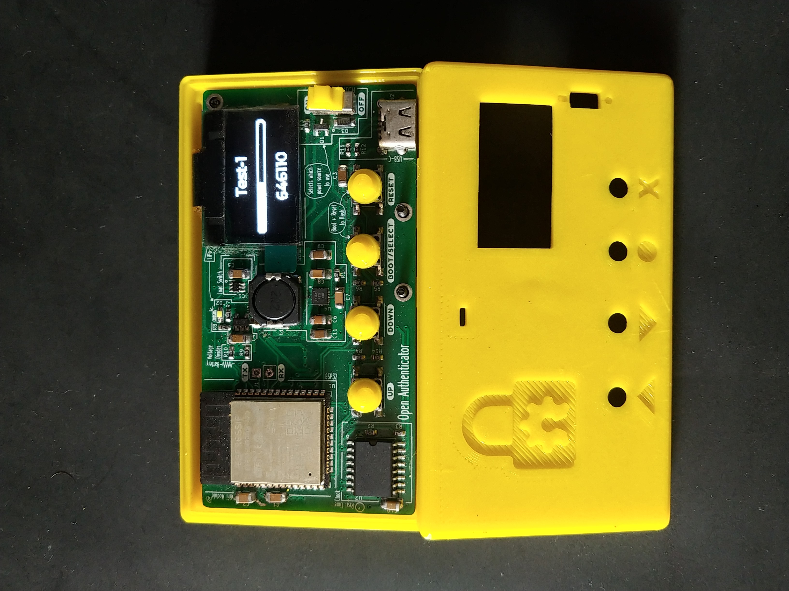
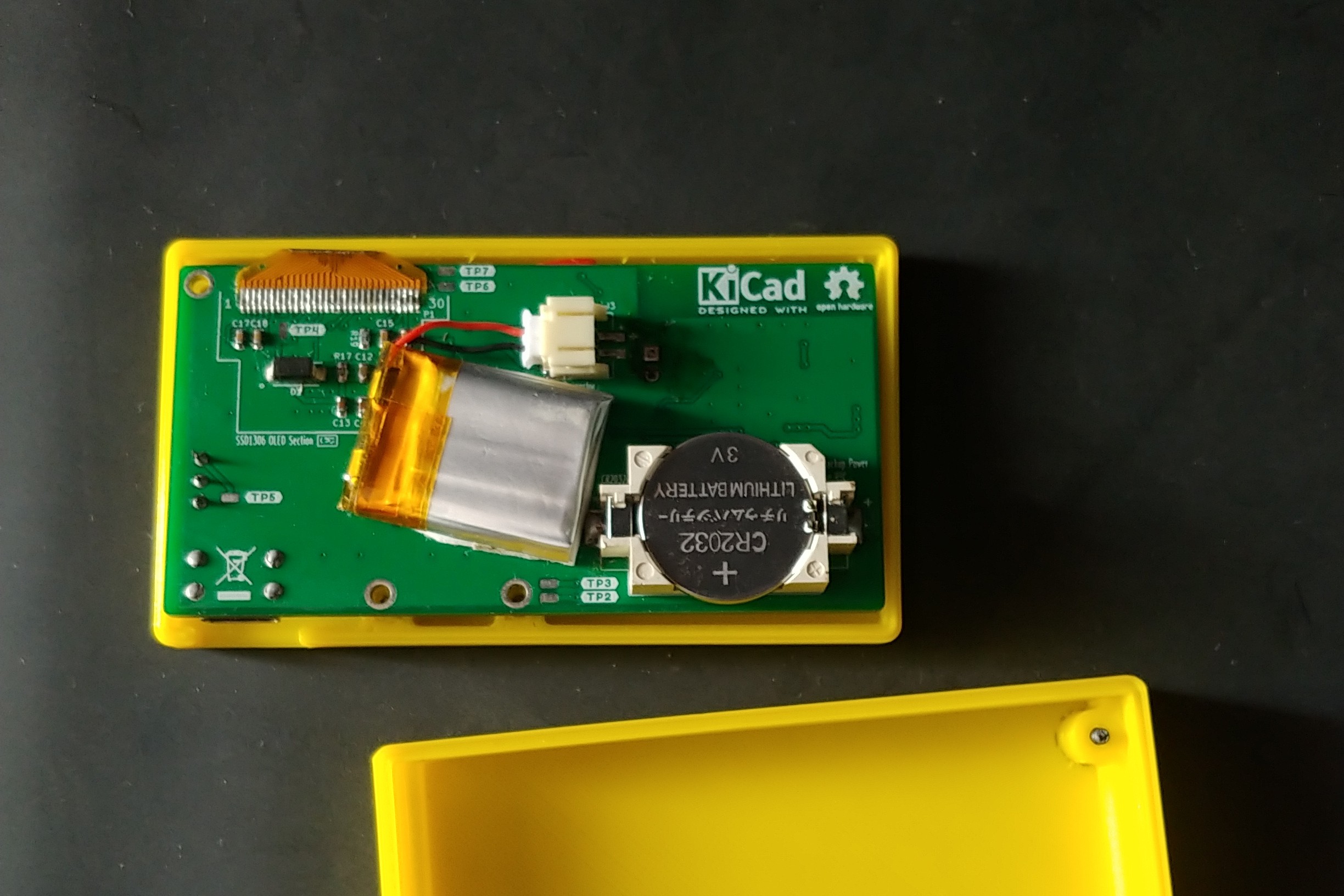
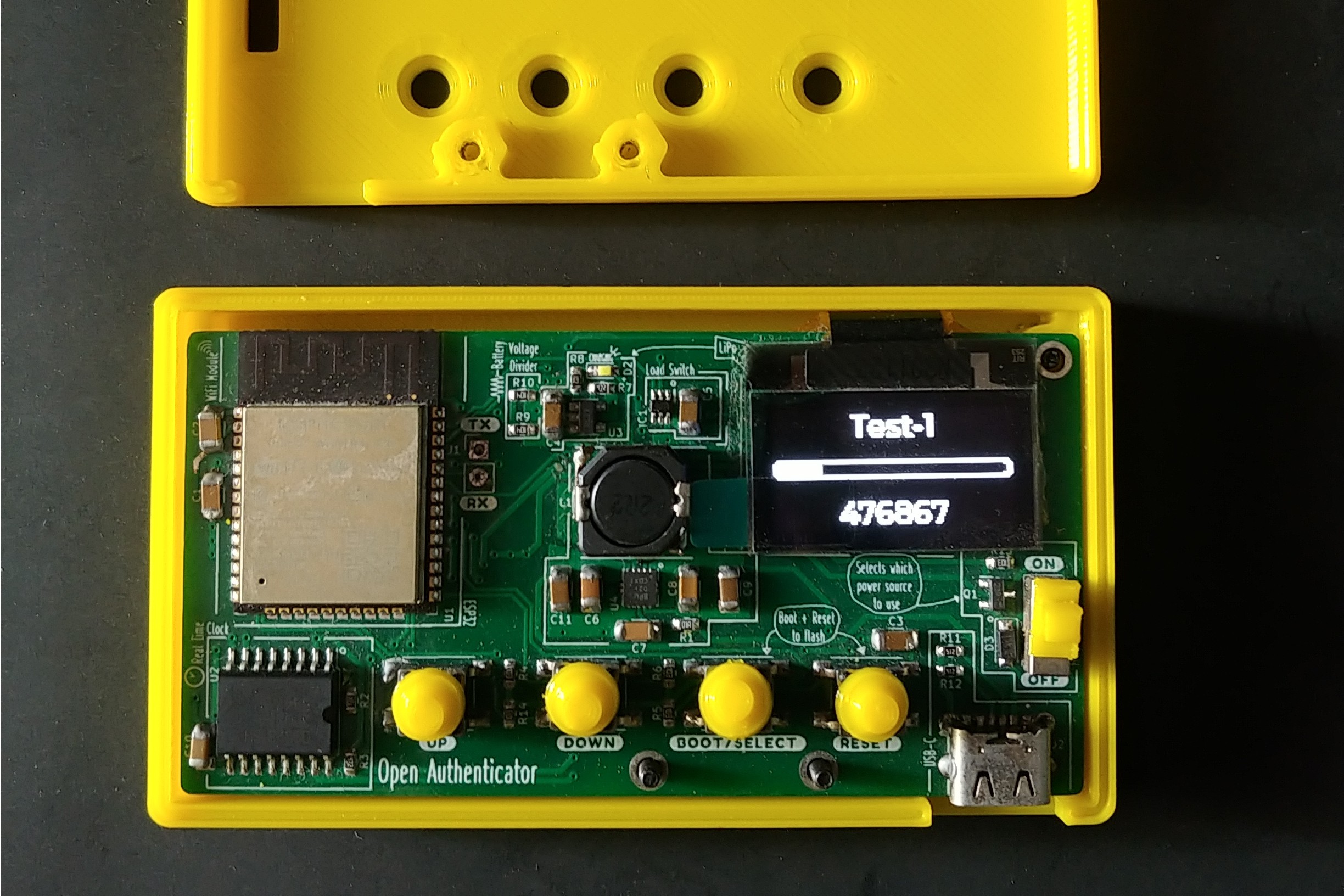
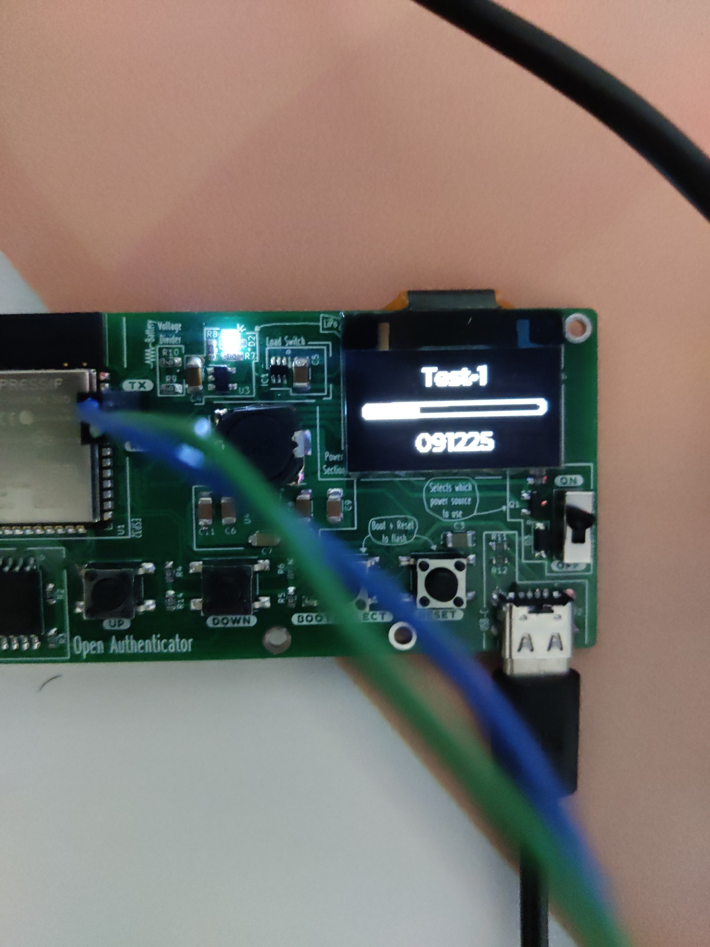
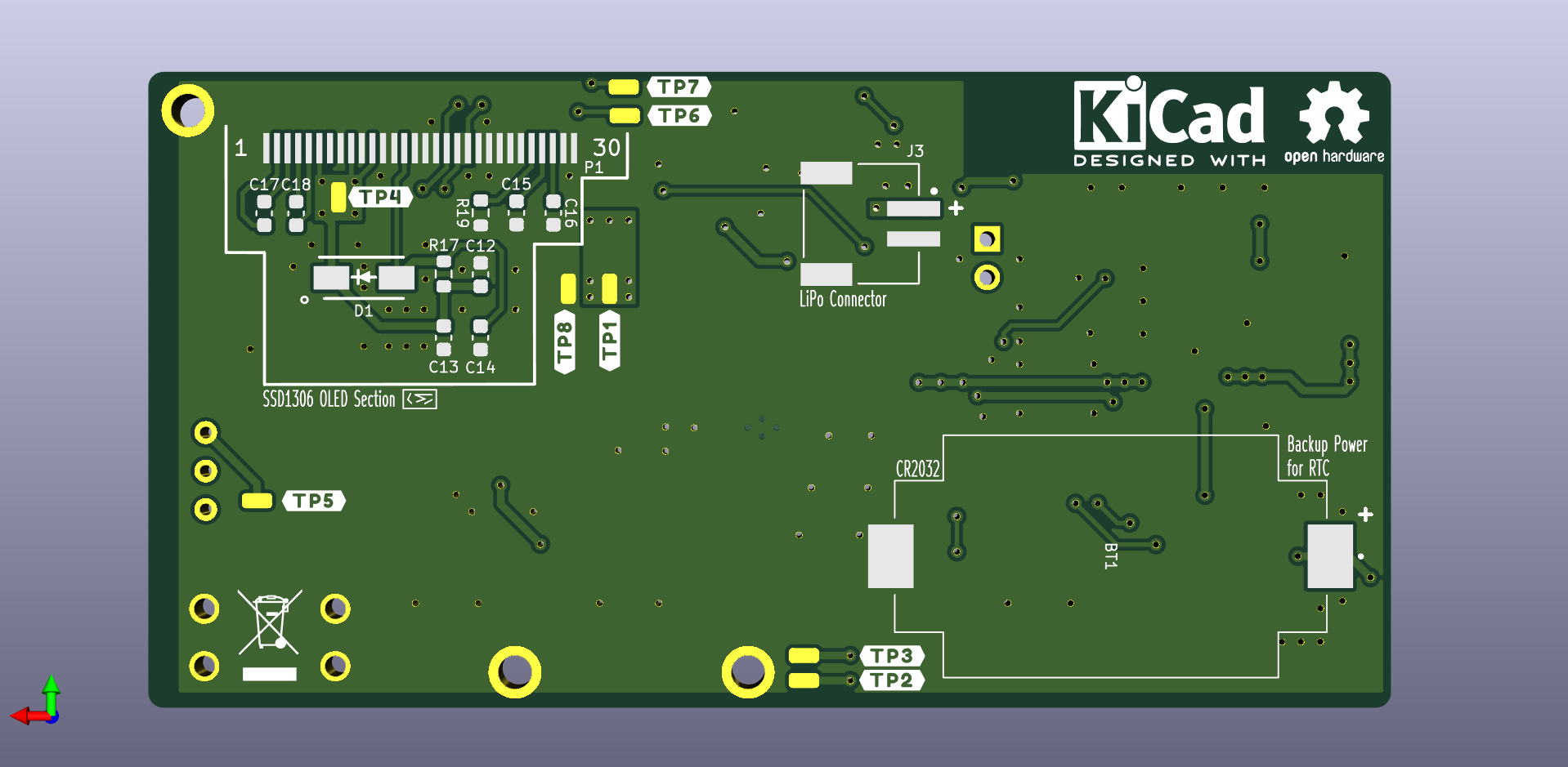
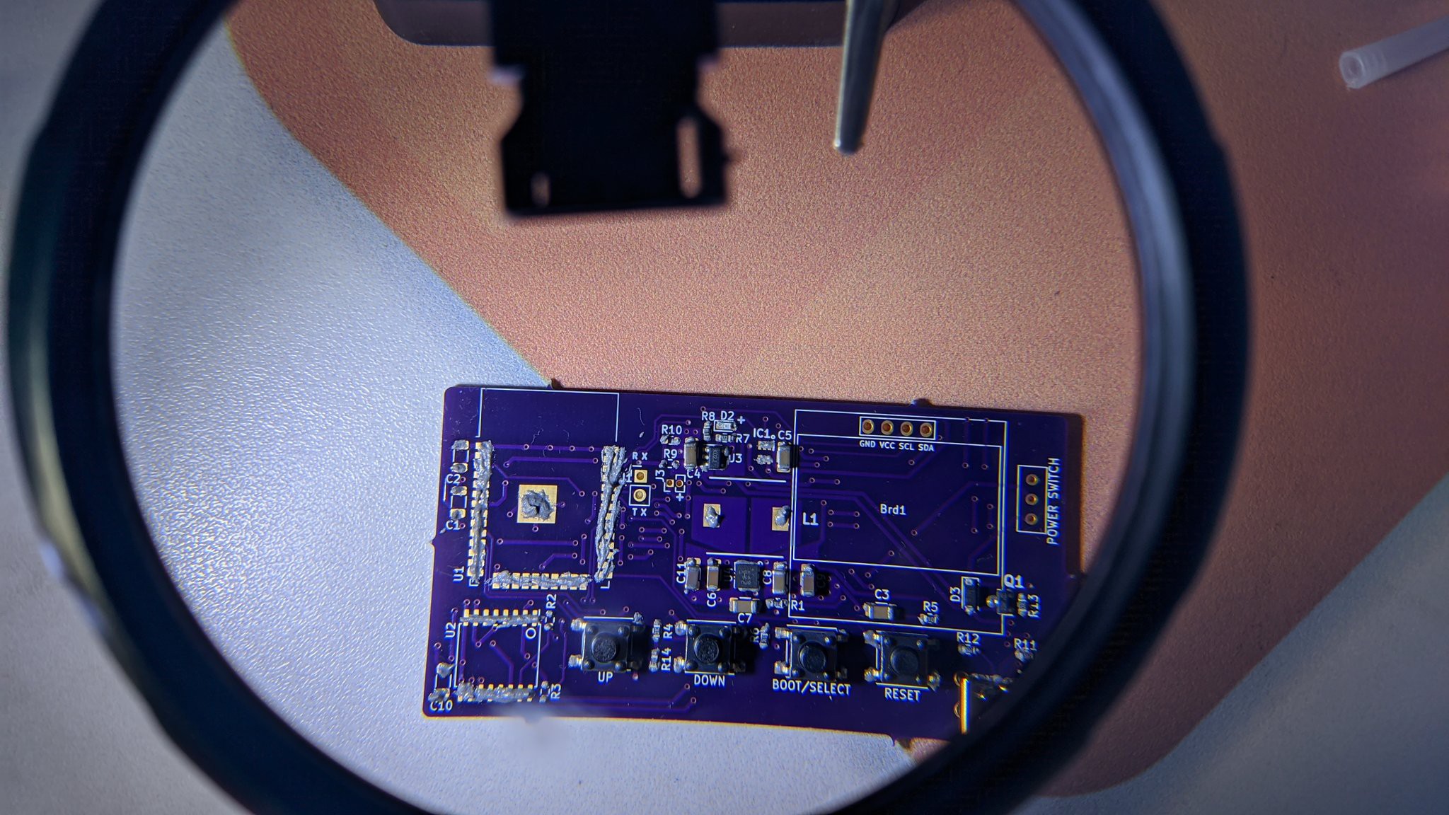
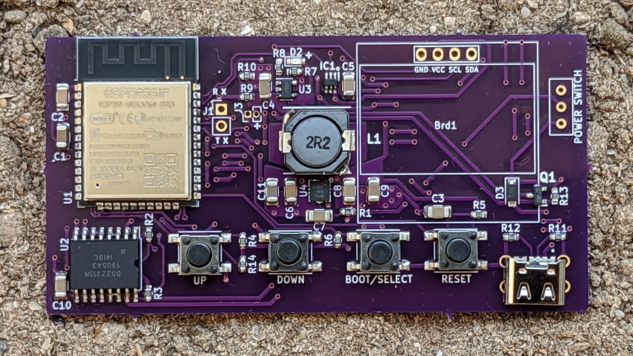
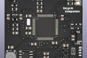
I wanted to take this to next level, make something like those RSA key id devices, but more configurable and not exactly use and throw like those and ESP32 was the right tool for it. So, I designed a PCB for the same. It was a long process, I had to handle my summer internship, finally by October I finished designing it and after getting it reviewed and rerouting again after two weeks, my PCB was ready to be ordered.

Thanks to guys at OSHpark, I got these PCBs for free, you can order it from here.
![]()
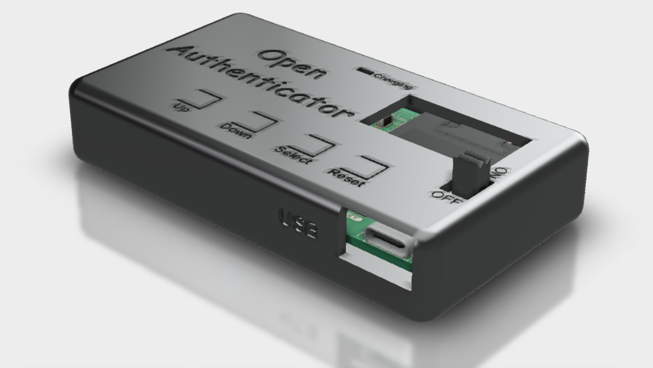
Thanks to PCBway for sponsoring the PCBA of final prototype.
You can checkout the project on PCBway here: https://www.pcbway.com/project/sponsor/Open_Authenticator.html

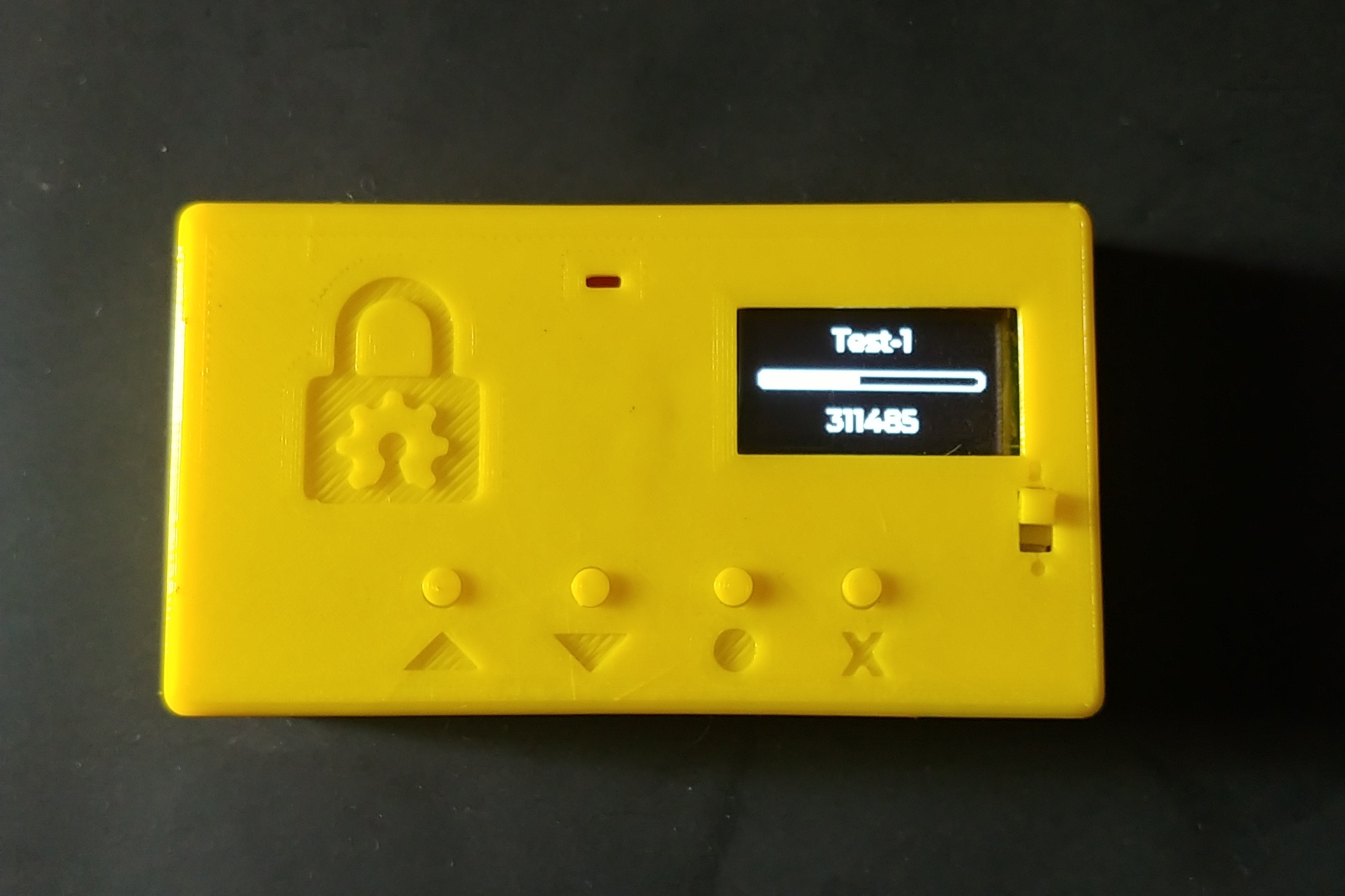
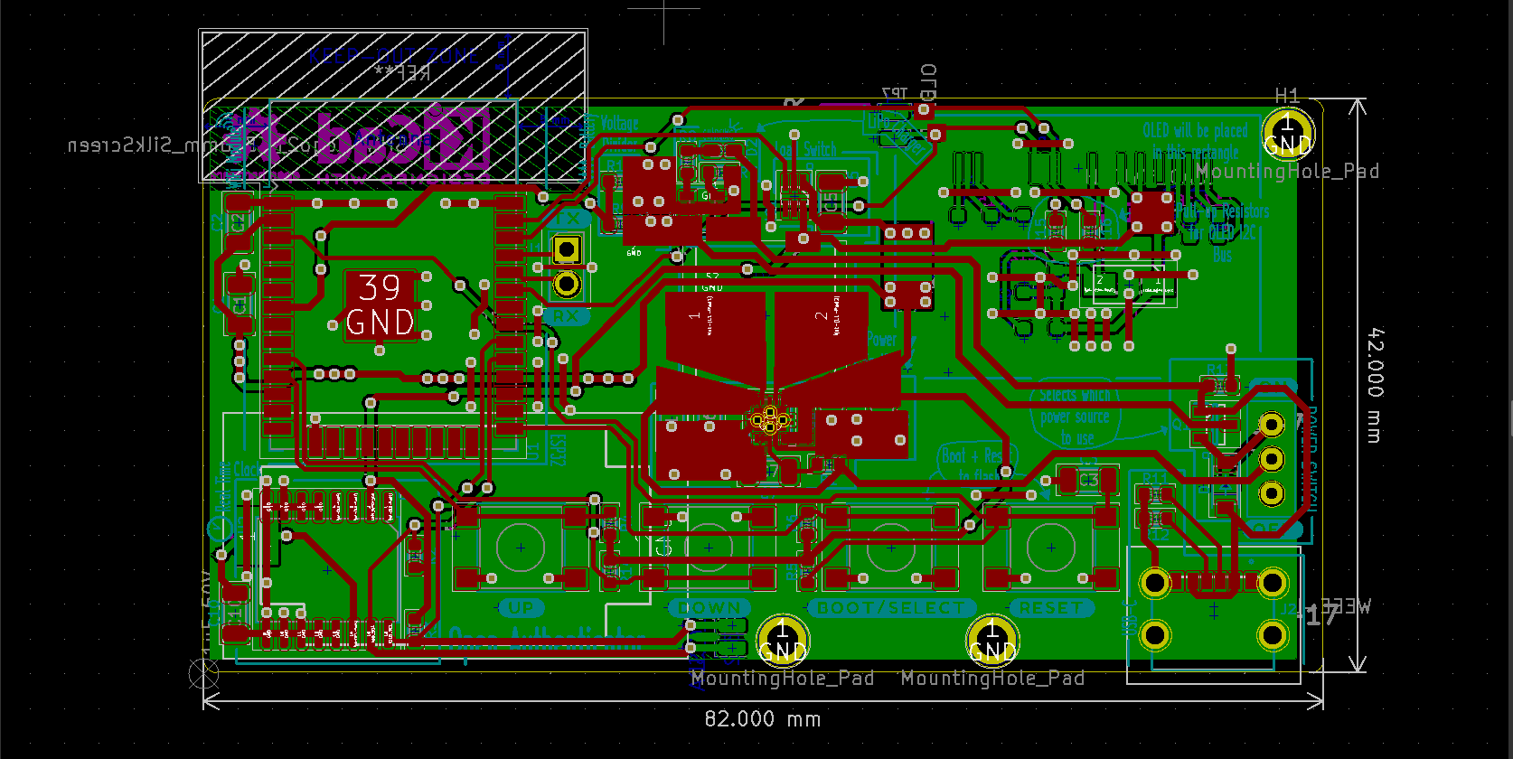
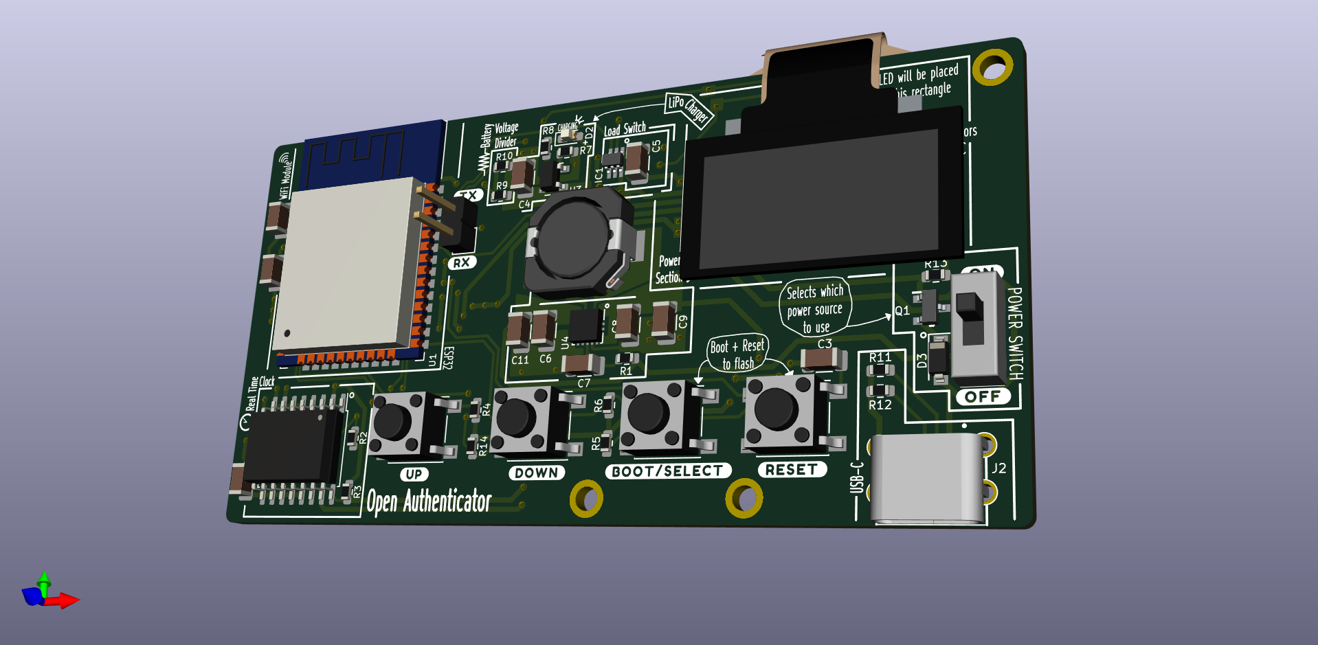
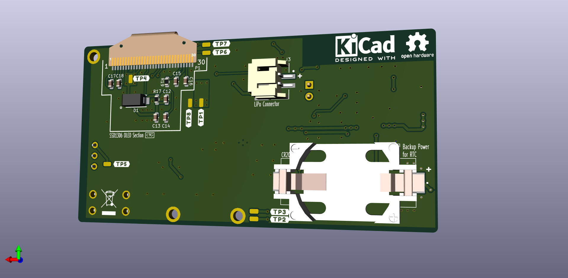
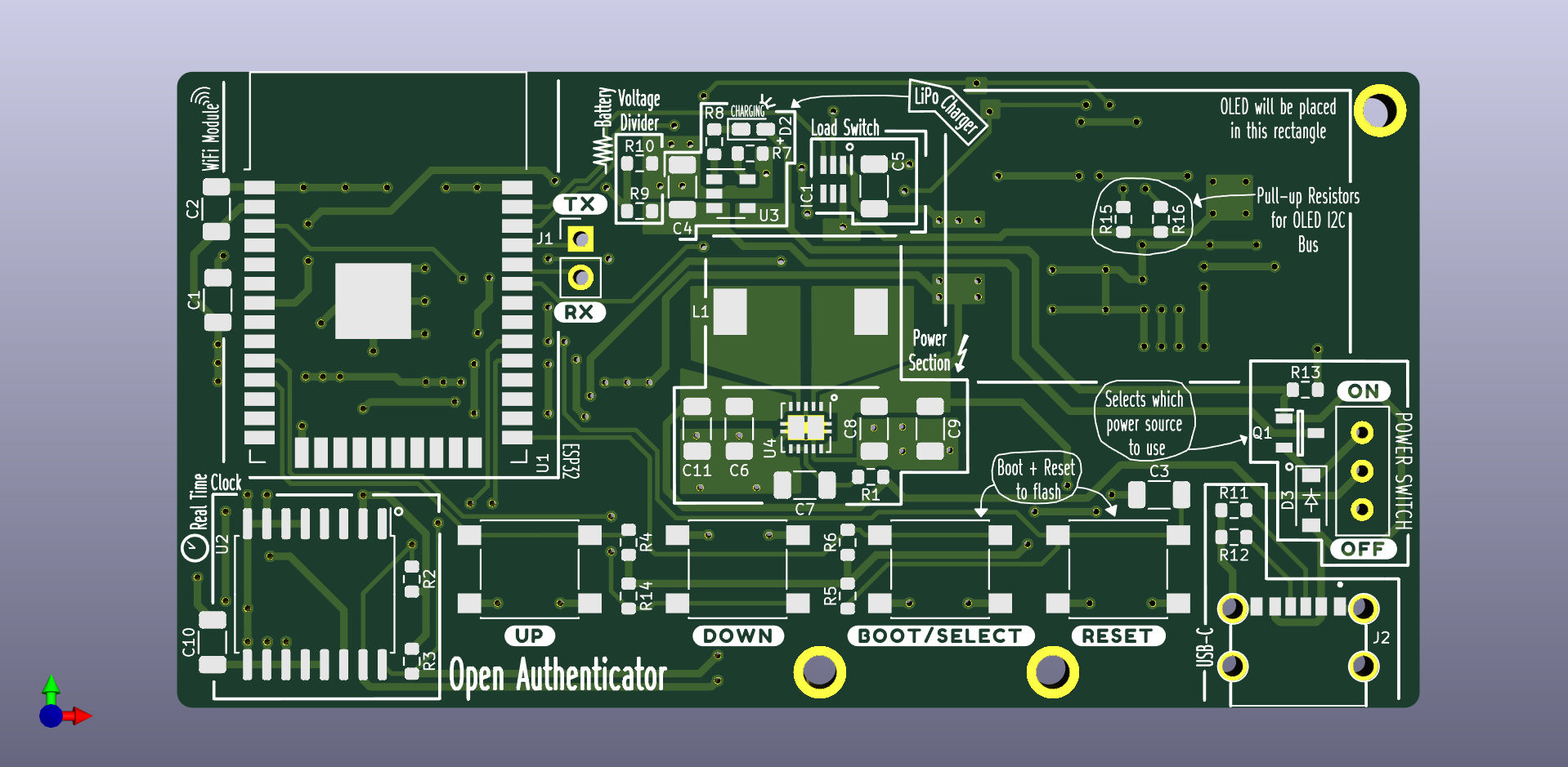
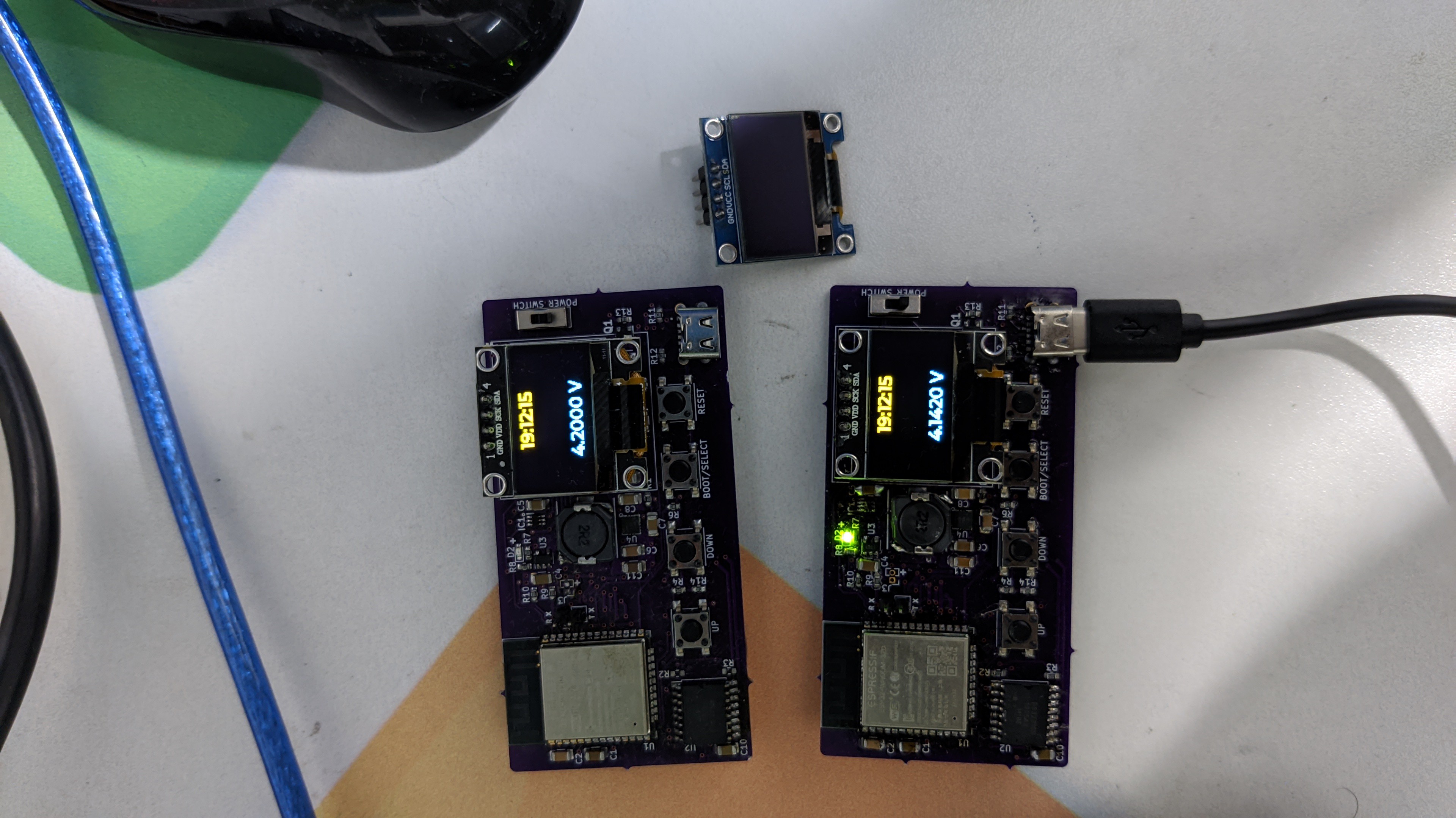
Details of the device
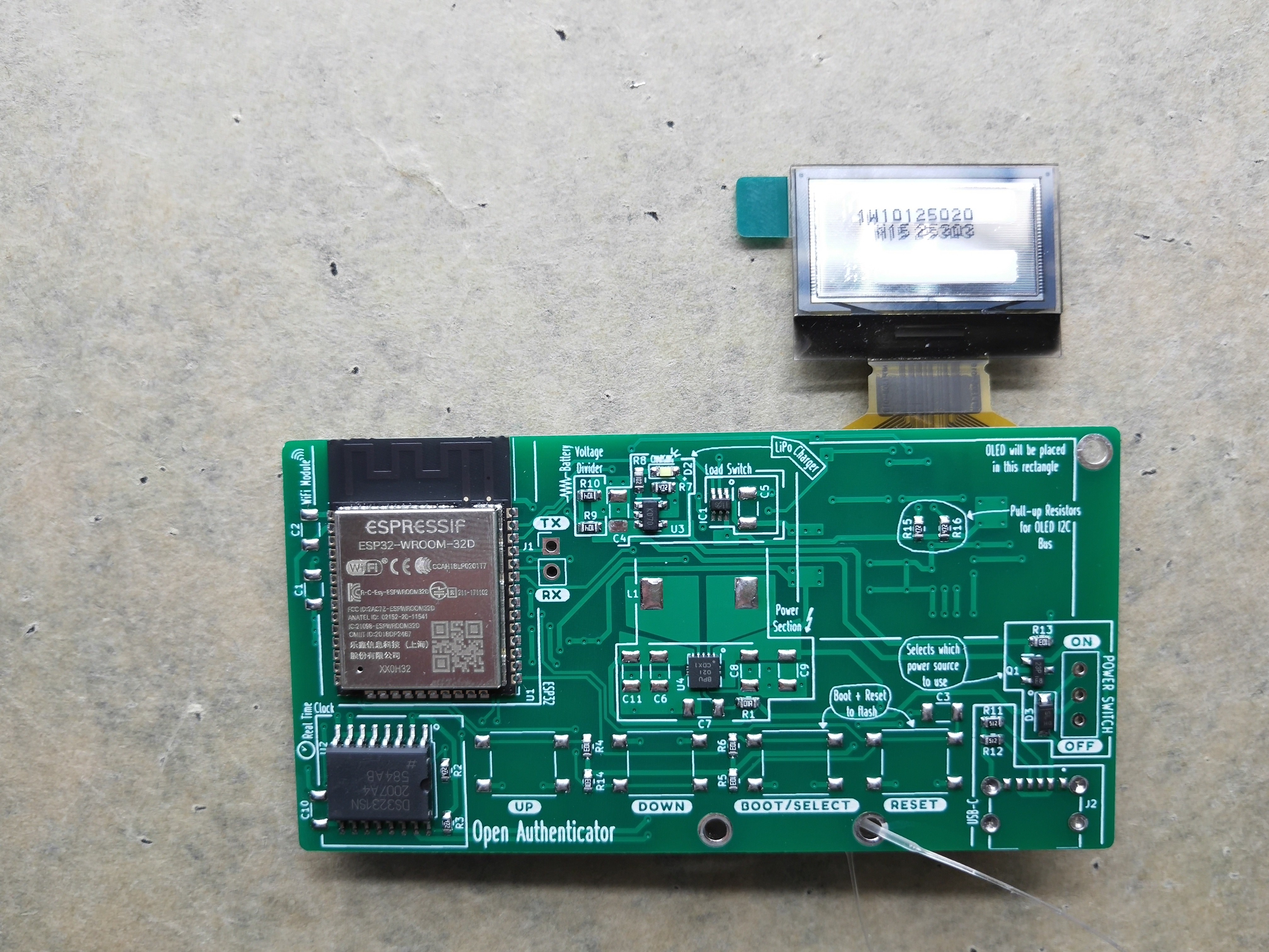
- Small form factor of 82mm x 42mm
- Uses ESP32-WROOM-32D module
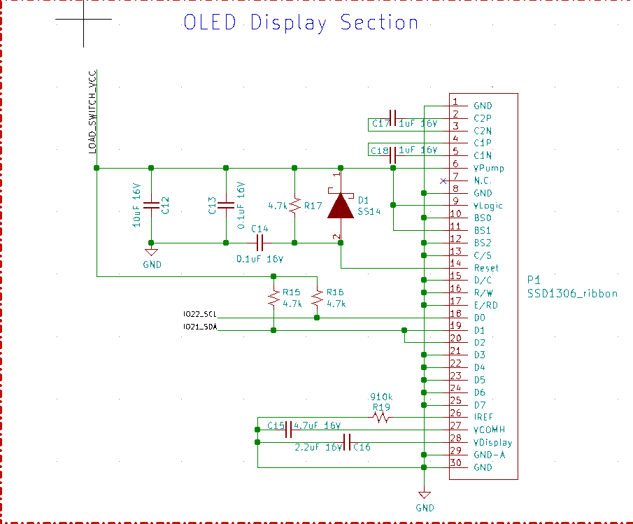
- Uses 128x64 0.96" inch OLED module
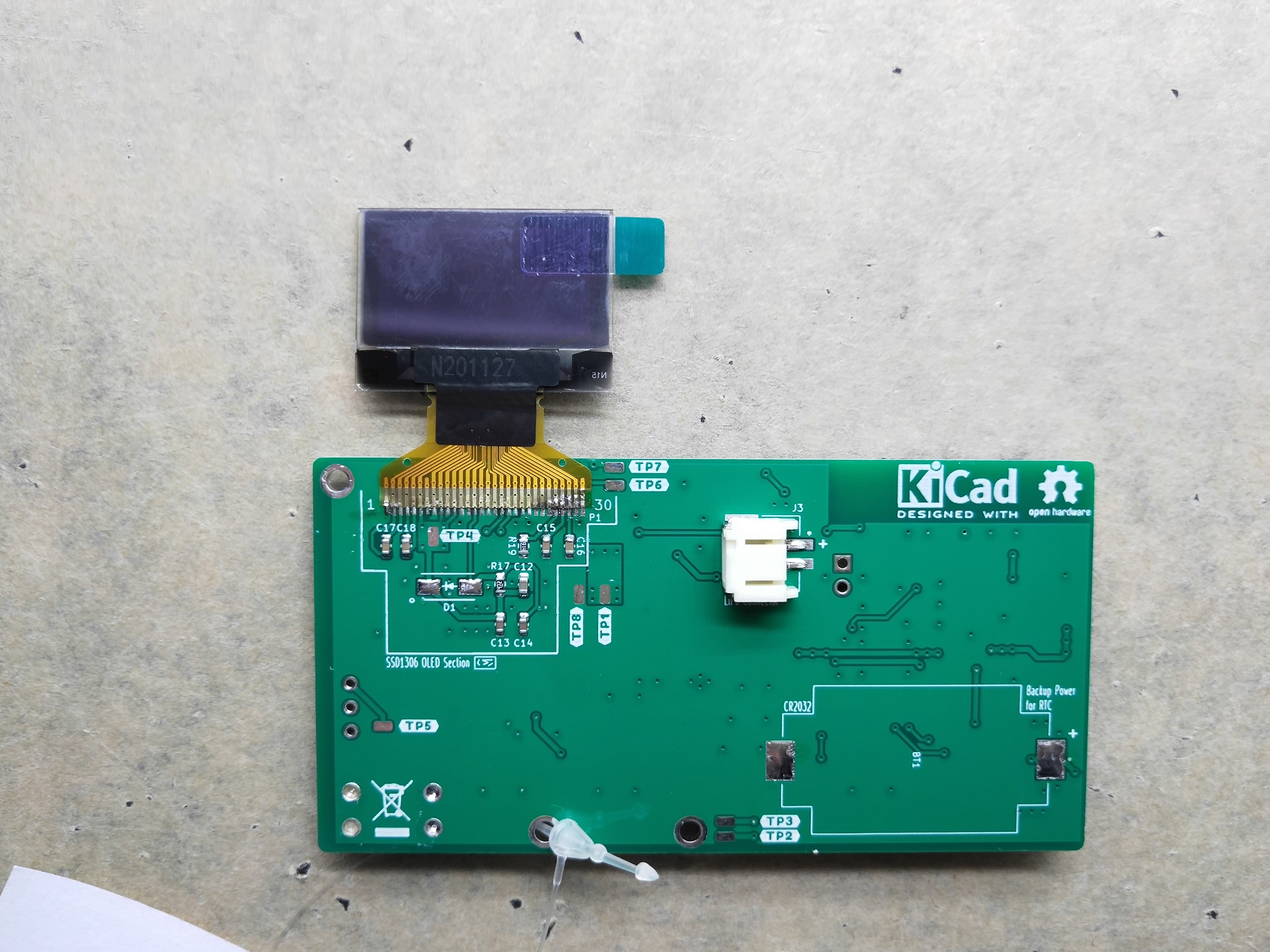
- Uses DS3231 RTC with battery backup (CR2032) for timekeeping
- Powered by 3.7V 300 mAh LiPo battery
- Uses MCP73831 for charging LiPo battery
- Uses TPS63001 Buck Boost Converter IC for efficient 3.3V power supply, with input range from 1.8V - 5.5V
- Uses TPS22919 Load switch to control power to OLED and RTC chip
- Autoselect power source, i.e., battery or USB
- USB Type-C for charging only (no data pins connected)


 Matias N.
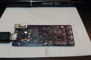
 morgan
 Edward Li
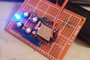
 K Gilbert
please add power to this device. and a month working time on one charge