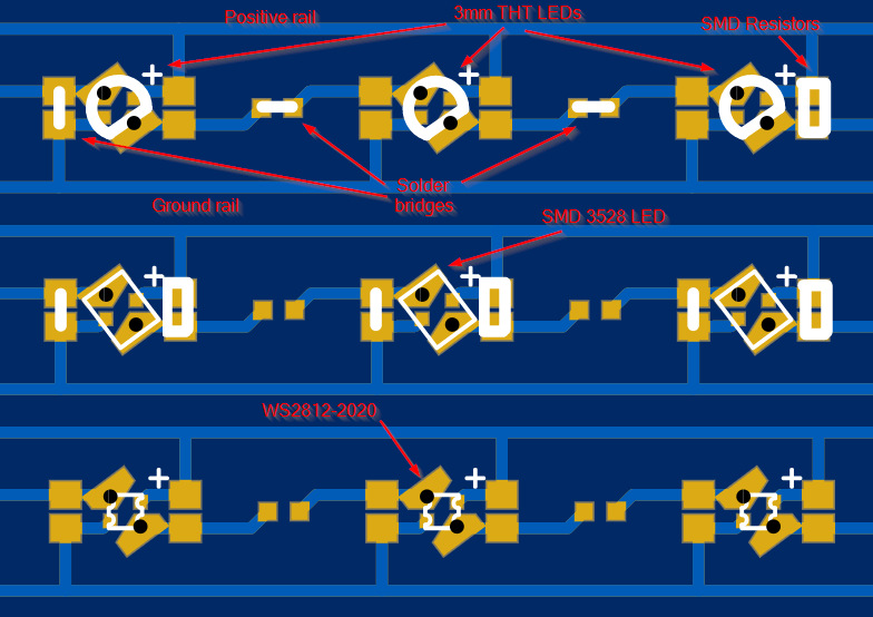
I'm not really a fan for RGB, in the {something}-puking-rainbows way, so my first thought was to use single color LEDs. This means I need to create some steady current through a resistor for each N pieces of LEDs. If you want to drive 105 LEDs from a battery, you need to minimize the power lost on the resistors, and limit the current quite a bit.
Plain battery driven LEDs
I was thinking 1 - 2 mA for each LED that would mean 105 - 300 mA which, when drawn from a single cell 3000 mAh tablet battery, would last 10 hours. But let's calculate power:
A single red LED has a forward voltage of about 2V. This means that in a single LED per resistor would consume
but the resistor consumes
This means about 54% of efficiency, tons of energy loss to the current limiting resistors. That's terrible to use in a battery powered application. Not only that, but the LED brightness in this context would significally vary with the battery draining over time. Since 3.7V is just the nominal voltage, and the real value will be somewhere within the 4.2-2.9V range.
Boosting voltage
However. If I stabilize the voltage with a simple boost converter module, how would it work?
Let's take the LED from teh previous example. 2V forward voltage driven with 1mA of current. If I boost the voltage to 12V, I could use 5 LEDs in series and a single resistor. This way the LEDs use
and the resistor would consume
This is way better, at around 83%. However, boosting the voltage comes at a price, which is the 80% of efficiency with the cheap chinese modules I'm planning to use. That means the total power consumed by the 5 LEDs and the resistor would be about 14.4mW which will result in the efficiency range of about 67%. That's less optimal, but still better!
As you can see the main source of power loss is the resistor. Lowering the power consumed by the resistor means raising the efficiency. As one can see, the power is driven by two factors: Voltage and current. As for the current we can't do much, we need to provide 1mA to the LEDs. So the only option is to lower the voltage dropped on the resistor compared to the supply voltage.
And yes, if we drop the voltage to 11V, the resistor will now only drop 1V, consume 1mW, lowering the total consumption to 11mW.
This is a figure of 91% efficiency before, and 73% after adjusting for the boost converter. Not good, but way better than the 54% we began with.
NeoPixels maybe?
One great feature of the WS2812 smart LEDs is that they have integrated LED drivers. This means, that this whole efficiency thing and the resistor stuff is not my F-type problem anymore. Or at least I have an excuse why my design is crap. All it needs is a 5V boost and a bypass cap, but I guess you can just leave the cap out and it would still work fine.
Concluision
Conclusion? There is none. I'm trying to design a PCB where all these are possible. Single LED per resistor, multiple LEDs per resistor, and WS2812. We'll see which one works. How would I achieve this? Take a look:

 rOzzy87
Discussions
Become a Hackaday.io Member
Create an account to leave a comment. Already have an account? Log In.