 Wenting Zhang
I know it has been a long time since I have finished the PCB design. I have finally had it soldered and working:
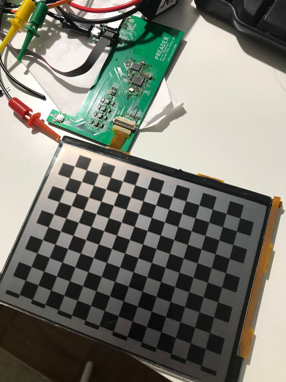
There aren't much to talk about right now, as the firmware is still mostly work in progress. The details about screen driving have been discussed in the previous log. But now with RP2040, It's possible to drive this screen at a refresh rate much higher than previously possible with CC1100.
This is a bistable LCD, and it takes ~1 sec to do a full screen update. But I would like to see, what if I don't need the image to be stable, but rather using it as a normal LCD? This first revision hardware also features a likely over-engineered bias generation circuit, to allow flexible bias generation to support high frame rate operation, if at all possible.
The answer is, yes, but actually no.
https://twitter.com/zephray_wenting/status/1382840220735971328
This is what it looks like when being driven at 30Hz, and the voltage is already at 32V. Driving it at higher refresh rate requires bumping up the voltage even higher, and will not improve the contrast ratio. This is the best contrast it could achieve when being driven like a normal LCD. So yes it could be, but the image quality is too poor to be used.
But what's happening here?
You've probably heard about different LCD technologies like TN, IPS, MVA for active matrix (TFT) LCDs. There are several different technologies for passive matrix LCDs as well: TN, HTN, STN, FSTN, and Double-layer STN (not to be confused with Dual-scan STN).
All passive matrix LCDs suffer from one issue: lines couldn't be driven individually. Think in an LED matrix scan situation, pixels in the active scan line are either forward-biased or zero-potential, and pixels in the non-active lines are either zero-potential or reverse-biased. But there is no reverse-bias in the LCD: they respond to the electric field, no matter its positive or negative. So all the unselected lines are being driven as well.
To deal with that, bias voltages and sophisticated driving waveform must be introduced. The goal is to make the RMS voltage on the active pixel higher than the RMS voltage on the inactive pixel (which is never zero, unfortunately). The contrast is then limited by two factors: the RMS voltage difference between active and inactive pixels, and how the LC responds to the voltage difference.
The first one is pretty much fixed value and can be calculated. The voltage difference decreases as the line count (vertical resolution) goes up. This means you are probably never going to see a very high resolution passive matrix LCD panel.
The second one could be improved by using different material and LC organization, which is doable but hard. TN only do well with resolutions under ~100 lines, and have poor viewing angle (20 deg or less). With STN technology and improved LC material, it is possible to scale up ~400 lines. With dual scan, which basically means putting 2 LC panels in one glass, the vertical resolution could scale up to ~800 lines. For this reason, there is basically no high-resolution TN passive matrix LCD. People had to use STN to get acceptable image quality.
So, what we are seeing here, is exactly a high resolution TN passive matrix LCD. It has extremely bad contrast ratio, just as expected. Yes though I expected that, but I still did it, just to see how bad it is.
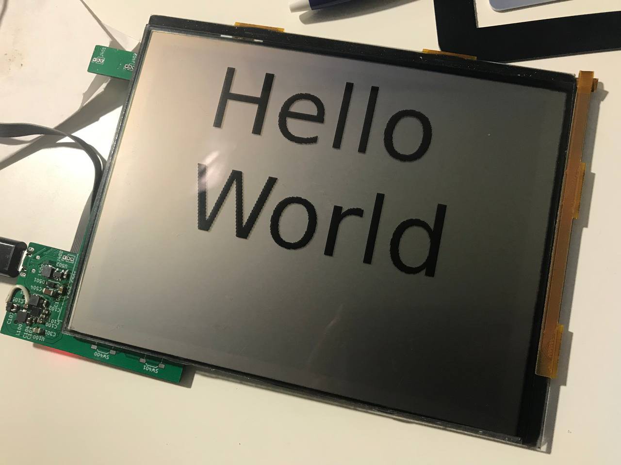
Note when driving them in the bistable scheme, the screen only needs to drive one line into the stable state, then move on to the next line. The rms value on the inactive lines only needs to be low enough so they are not being driven into stable state, instead of low-enough to be invisible. In this case, the contrast ratio limitation no longer applies. The end result is an extremely high contrast image, that is very unlikely to be seen on other high-res passive matrix screens:
Discussions
Become a Hackaday.io Member
Create an account to leave a comment. Already have an account? Log In.