 Nick
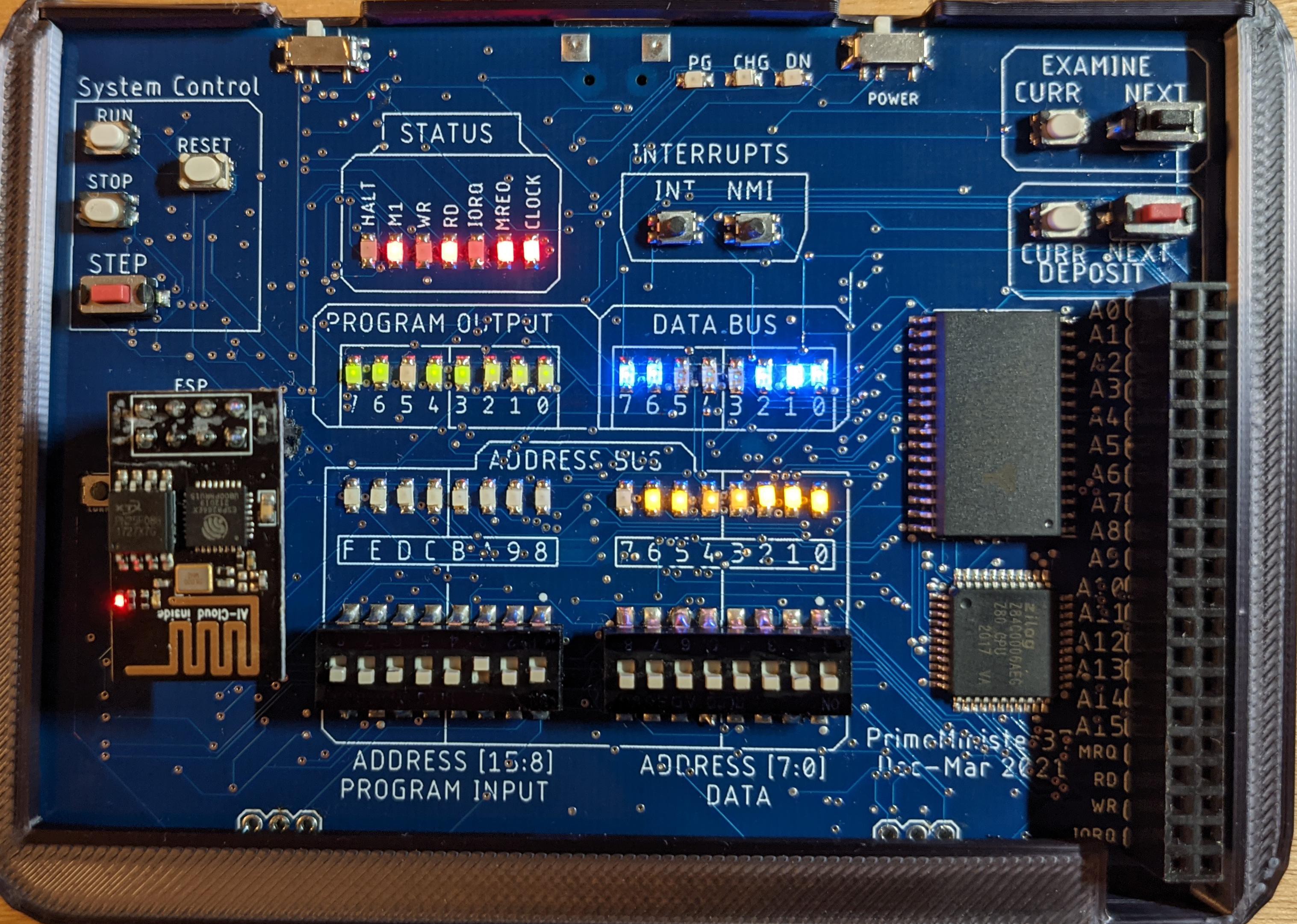
NickThe Version 2 board is complete!
This is a 4-layer PCB, and includes WiFi support, as well as headers for accessing all Z80 signals.
There is a draft of a user manual available here. There are numerous improvements to the CLI, and the general management of the Z80.
Runnable jar file and source code for the loader are available here.
Source code for the ATMega328 controller is here.
Board files - PDFs of the schematic, top and bottom of the board; as well as Eagle .brd and .sch files are available here. NOTE: The current version (A045) includes a bug in the I/O port addressing: a jumper wire is needed to restore addressability. This will be fixed in a subsequent version.

The main purpose of this project is to have fun soldering lots of tiny components onto a PCB :) The secondary purpose is to implement a pocket-sized system similar to the old IMSAI 8080

allowing front-panel manipulation and exploration of machine code.
Main Goals (form the original system):
- ability to enter and examine code via front panel switches
- display of address bus, data buse and system signals via banks of LEDs
- deposit Next/Examine Next option
- system can be in RUN or STOP state (different from HALT)
- input and output of user data (IN and OUT instructions)
- ability to single-step the CPU
Additional goals beyond the original system:
- pocket-sized
- rechargable
- Z80-based
- ability to save/restore main memory in non-volatile storage
- full system control (including a basic disassembler) through a command line interface via USB port
- multiple granularity of single-step (T-cycle, M-cycle, M1-cycle)
Wish-List (implemented in prototype to varying degrees):
- WiFi support (DONE)
- Allowing access to bus signals via headers (DONE)
- Make use of ATMega328's flash to save configuration info: default step size, default radix, power-up running or stopped, etc. Also give user the option to load (and optionally run) from flash on power-up.
Out of scope:
- S-100 bus (not implementing this)
- Peripherals
- most anything else I haven't thought of!


 Dan Julio
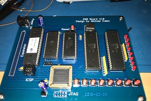
 Michael Cullen
Hi
I also have the problem with 0xaa
can you provide me your " send_now_special( PS2_KC_RESEND ); // hacked " or post it here
regards