Nick
Nick-
PCB Fab
03/03/2021 at 23:51 • 0 commentsI'd been using PCBWay and really enjoyed working with them. They're fast, friendly and helpful. They have cool videos on their website showing the fab process. They'd also been very fast, until these boards. They were made right before Chinese New Year, and they hit several snags leaving the country and entering the US. They hit Portland right as a snowstorm came in, and they spent a couple of weeks "held due to an Event Majeur." During this time, I got frustrated waiting, and so I re-ordered (after fixing some bugs I'd noticed) from JLCPCB. That second order arrived the same day as the original boards, so I mostly used the 2nd set.
I still order from PCBWay, but for 4-layer work, JLCPCB seemed a bit faster and cheaper, so I went with them for this latest order.
-
Next Version
03/03/2021 at 23:45 • 0 commentsSo I used one of the boards to test the 5V boost again (with a pair of 22 uF vs 22 pF output caps; and with more-careful soldering to avoid bridges etc.) and it works great! Seems to be a nice solid 5V output, and I can use it to drive the system AND a LDO 3V3 regulator driving an ESP-01. So I'm ready for the next version, which includes the WiFi interface and edge connectors for address/data/memory/control bus signals. Moved to a 4 layer PCB (and commercial version of Eagle).
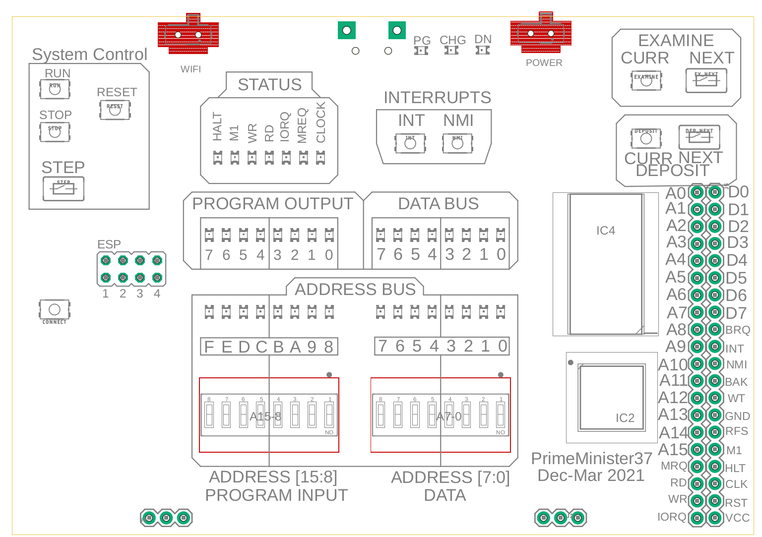
![]() Here's the new front panel. ESP-01 goes on the left, power for that is on the upper left (it draws a few hundred mA, so powering it off when not in use is good). The CONNECT button on the left simply grounds the ESP's RESET pin, forcing a reboot of the flash code in the ESP.
Here's the new front panel. ESP-01 goes on the left, power for that is on the upper left (it draws a few hundred mA, so powering it off when not in use is good). The CONNECT button on the left simply grounds the ESP's RESET pin, forcing a reboot of the flash code in the ESP.For better routing, I moved the Z80 and SRAM to the front of the board. They're the main stars anyway :)
-
Works Great!
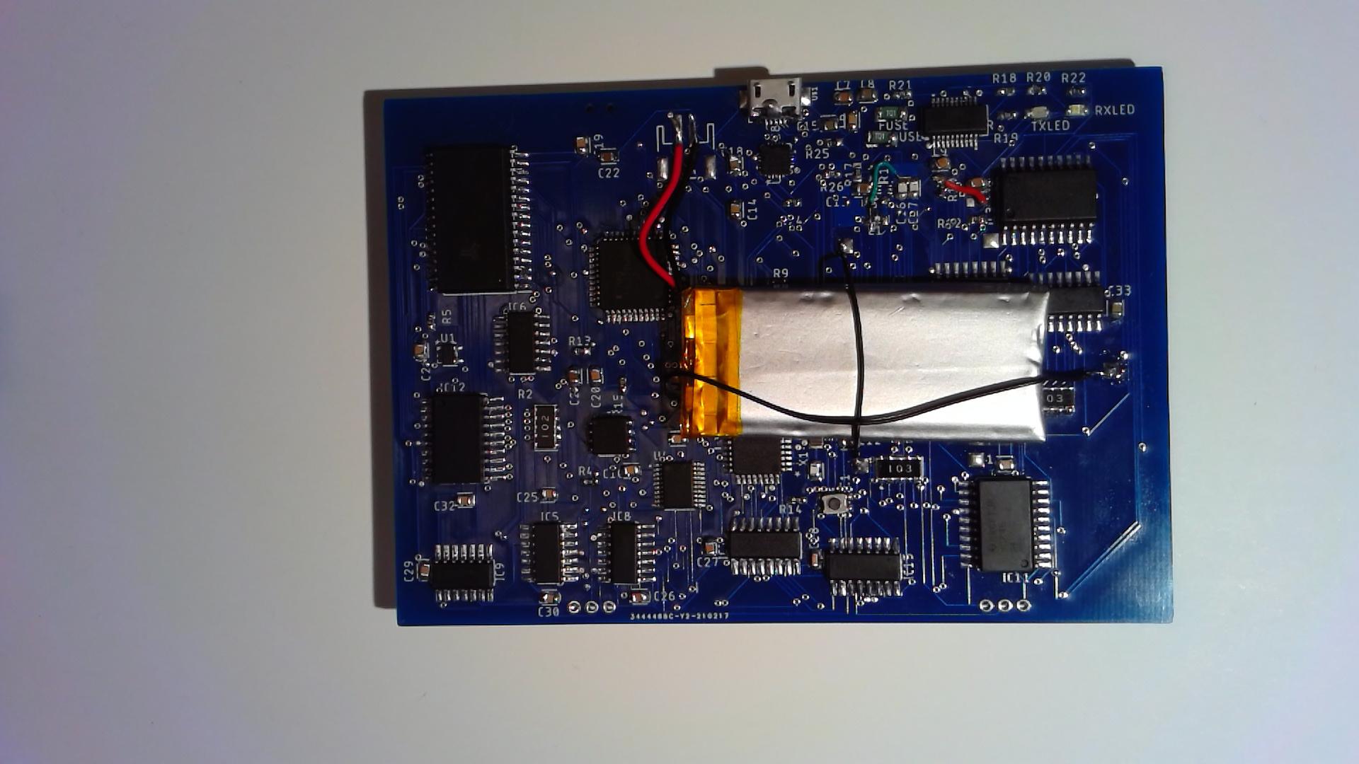
03/03/2021 at 23:37 • 0 commentsThe board seems to be working perfectly! Building it up took me about 8 hours (I'm still relatively new to SMD work), and other than the few issues mentioned in the prior log, it all worked as expected.
I found that solder paste + hot air isn't as precise as hand-soldering for me, and some of the parts which are close to vias ended up shorting in the process. Hand soldering is more fun anyway :)
The 3D printed box I had made earlier worked out great.
![]()
-
First Tests
03/03/2021 at 23:30 • 0 comments![]()
So the boards showed up (it seems they were riding around town in the back of a delivery truck for a few days). I soldered one, which resulted in a mostly working board :) A few issues:
- the 5V boost vented Magic Smoke when first powered. Used 22 pF instead of 22 uF on the main output (ooops!) I bypassed the boost, and the 3.7V power seemed fine for the whole board!
- The SRAM is really 128KB, and I left A16 floating. Shorted that to the adjacent pin (A14) and the SRAM stabilized. I'll ground it in the next version, maybe farm it out to an edge connector later for rapidd context switch :)
- The register I'm using for latching user output (OUT opcode) has an active-low CLEAR input. I tied that to ground by mistake, so user output was always 0. I wired it to a nearby 5V+resistor point, and that works fine now.
-
More Shipping Delays
02/12/2021 at 21:16 • 0 commentsThese boards are forever delayed. Multiple holds in China; 24 hr hold in LA; another 24 hrs to get to Seattle...another hold in Portland. Guessing they'll arrive Mon or Tue (a week after DHL's original estimate).
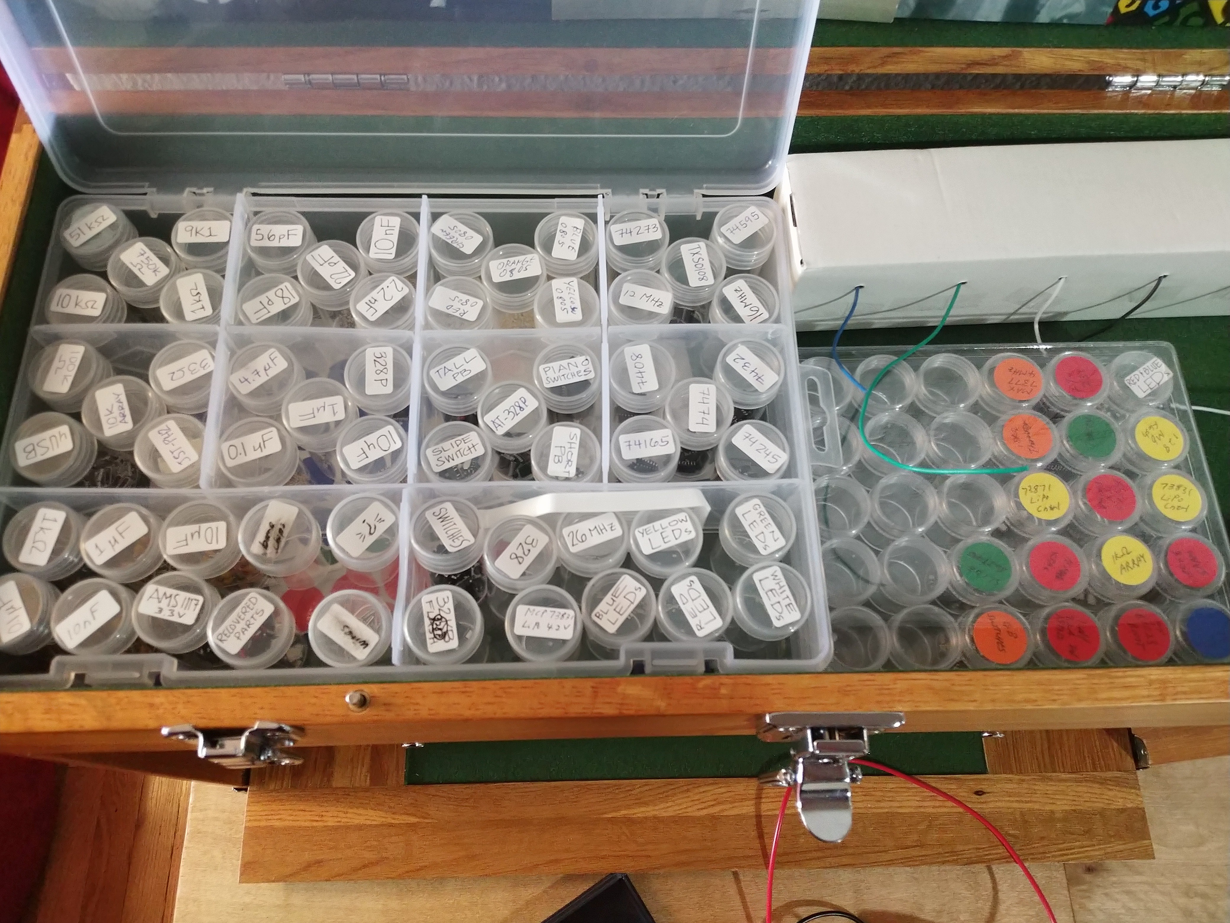
Meanwhile, I've been working on the WiFi interface (main issues turned out to be power) and the control software. Write the CB- and ED-prefix disassember code, and got unstable-state-detection working. Have an order of building worked out, all my parts sorted and organized. My fiancee loves organizing things as much (or more!) as I do, so we've been going through parts and labeling/containerizing them. Now all I need is the PCBs!
![]()
-
Boards on the way again
02/08/2021 at 06:34 • 0 commentsI ordered my boards last week from PCBWay. They were delayed because of pre-New-Year's rush. Then 2 of the boards failed testing, and they wanted to confirm with me that they should still ship the working ones (Yes, please do!) They almost made it off the mainland, but hit a Clearance Event, meaning some sort of paperwork holdup. After a day+ of no visible change, they just cleared, and are on their way again. The original arrival date of Tuesday is still listed, but seems unlikely now. Nonetheless, I already finished writing this week's midterms, so my plate is clear all week if they do show up, and clear for other things if they don't :)
-
Multi-Byte Madness
02/08/2021 at 06:30 • 0 commentsSo one difference between my board and a real Imsai 8080 is, well, I'm not using an 8080! I'm using a Z80, which is mostly code compatible. One difference though is that the Z80 designers re-purposed some unused opcodes to add a lot of new instructions to the Z80. They did this by using those opcodes as prefixes to multi-byte opcodes.
I didn't think this would affect anything, but it turns out the bus signals seem identical whether fetching the first or second byte of one of these instructions.
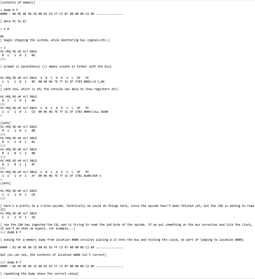
Why does this matter? Suppose you want to examine memory. This is done by forcing a JMP (0xC3) onto the data bus, followed by the desired address (which appear as operands to the JMP instruction). Obviously you don't want to do this in the middle of an instruction decode/execute, so I wait until M1, MREQ and RD are all active (meaning an opcode fetch is in progress). But this could well be the second byte of a multi-byte opcode fetch, which would be a problem.
Handling this has taken a few days of thinking, hit-and-miss, trial and error. It's slippery. Not only while stepping or ticking the clock, but also if the Z80 is free-running and then we stop it, we have no idea what just happened, and if a multi-byte opcode fetch may have been started.
My solution is to change the prompt -- from ">" to "(>)" -- whenever it can't be determined that it's safe to tinker with the bus.
--------------------------------------
LONG DETAILED EXAMPLE [comments in brackets]
![]()
-
ESP-01 Fun
02/07/2021 at 06:07 • 0 commentsI've had a wireless interface to this working for a while, but want to reduce it to as small an add-on as possible. Got some ESP-01's which seemed like the right size. All they need to do is route between WiFi and TX/RX.
Got a small burner from Amazon, loaded a simple script, and it works great! WiFiManager (Arduino library) is awesome. When you first run it, it offers a captive portal for selecting a router and saving credentials. After that, it always connects via that access mechanism, and then runs your script. If the router isn't available, it goes back to captive portal mode.
When I tried wiring an ESP-01 stand-alone (i.e. without the burner board), I mostly couldn't get it to boot, though sometimes it would randomly work.
I had EN and RST pulled high, but that wasn't sufficient. I believe I found the problem though :) Normally, to pull multiple inputs high, I'd run a single resistor to Vcc and tie all the inputs together. I think one or more of the inputs temporarily goes into output mode (and drives LOW) during boot, and, since it's tied to other inputs, they are driven low too, which, in the case of EN, is a bad thing.
There was some testimonial evidence that tying EN directly to Vcc sometimes helps. I suspect this may be the reason: it may have worked in cases where multiple inputs were tied together and pulled up.
Anyway, it boots every time now, which is great. Gonna use a SP3T power switch to drive the main board (T2) and then the ESP-01 (T3). So middle position is board only, 3rd position enables the WiFi. So no extra power draw in position 2 :) In position 3, I'll use the power going to the ESP to flip a pair of MUXes and connect the ESP's Tx/Rx to the AT328 (and disconnect the FT231).
Plans...
-
Starting Log
02/06/2021 at 20:02 • 0 commentsOpened HackADay account to begin tracking this project. Will eventually make public once I see it works :)
Pocket-Sized Imsai-Style Z80 Board
Similar to the old IMSAI 8080, but small enough to fit in your pocket :)
 Here's the new front panel. ESP-01 goes on the left, power for that is on the upper left (it draws a few hundred mA, so powering it off when not in use is good). The CONNECT button on the left simply grounds the ESP's RESET pin, forcing a reboot of the flash code in the ESP.