 deftcoyote
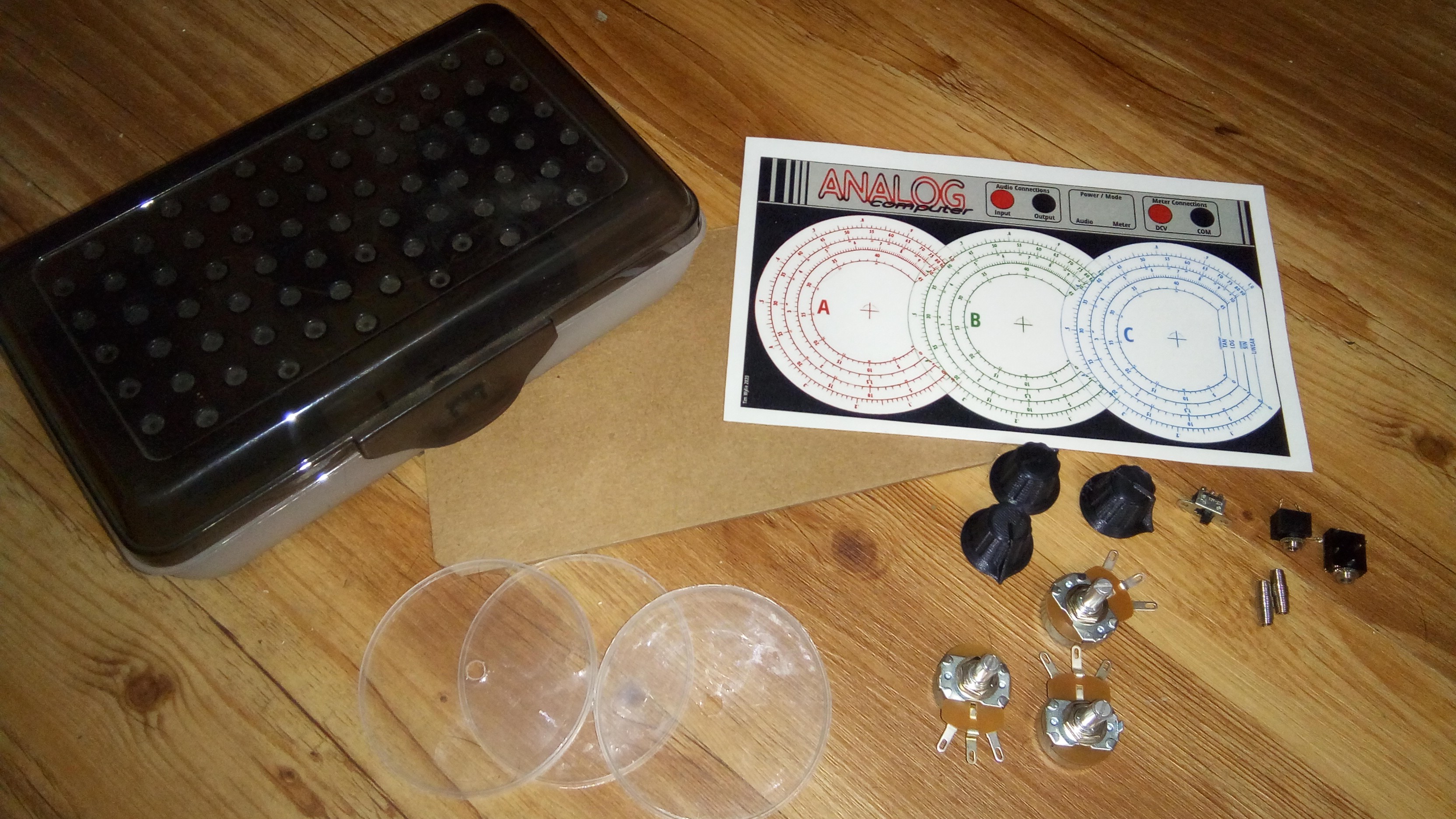
The pieces used to build the analog computer.
- 3 knobs that are 3d printed (https://www.thingiverse.com/thing:3460654)
- 3 potentiometers (Two 50 Ohm, One 1K Ohm)
- 2 springs
- 2 headphone jacks
- 1 SPDT switch
- 3 pringles lids or circles cut from clear plastic
- battery holder that is 3d printed (https://www.thingiverse.com/thing:3115171)
- a pencilbox :)
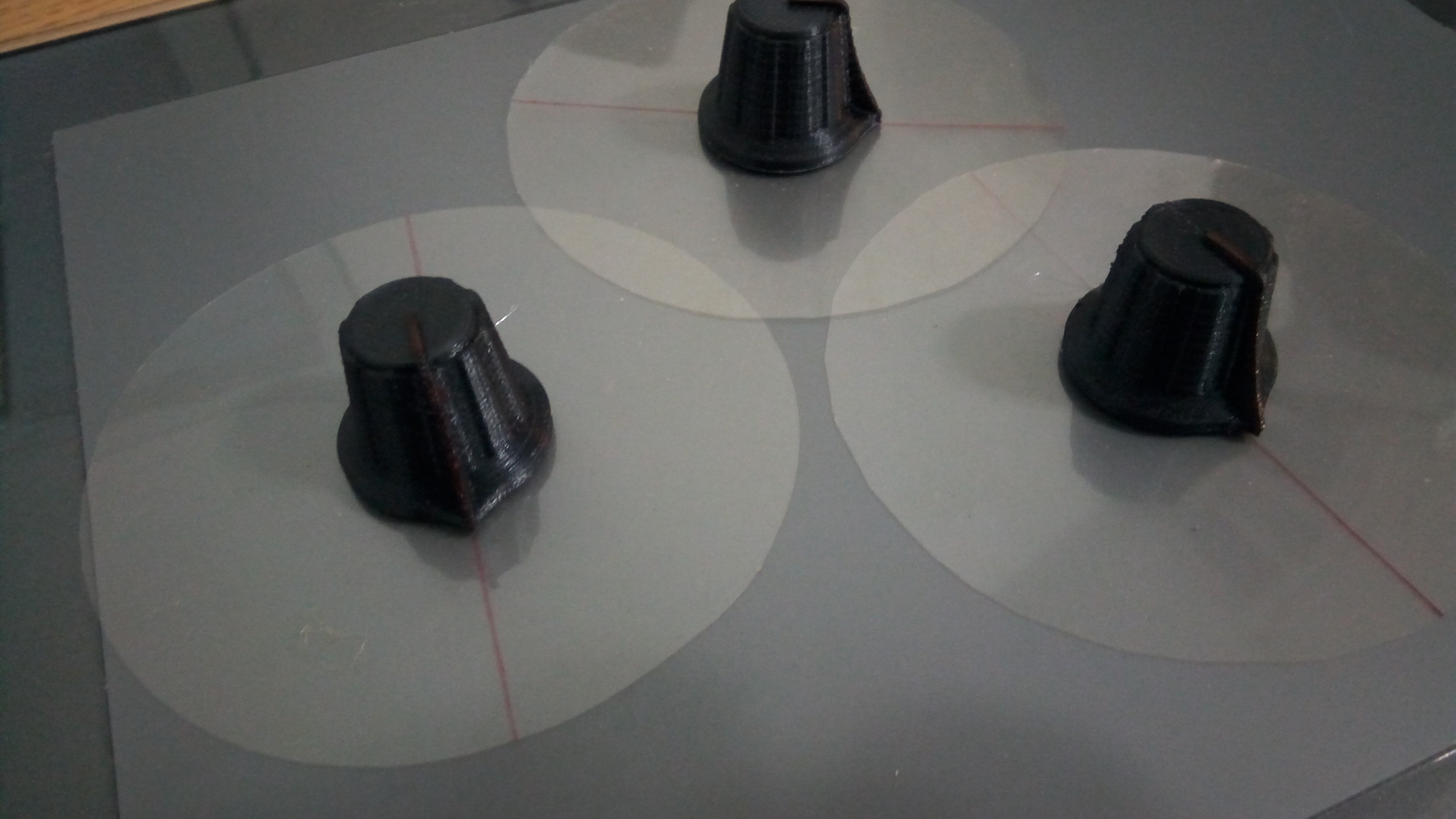
For space, I overlapped the 3 potentiometer gauges. Rather than 3d print needles, which might hit each other, I glued the plastic circles to the knobs and drew a line on it for the needle.
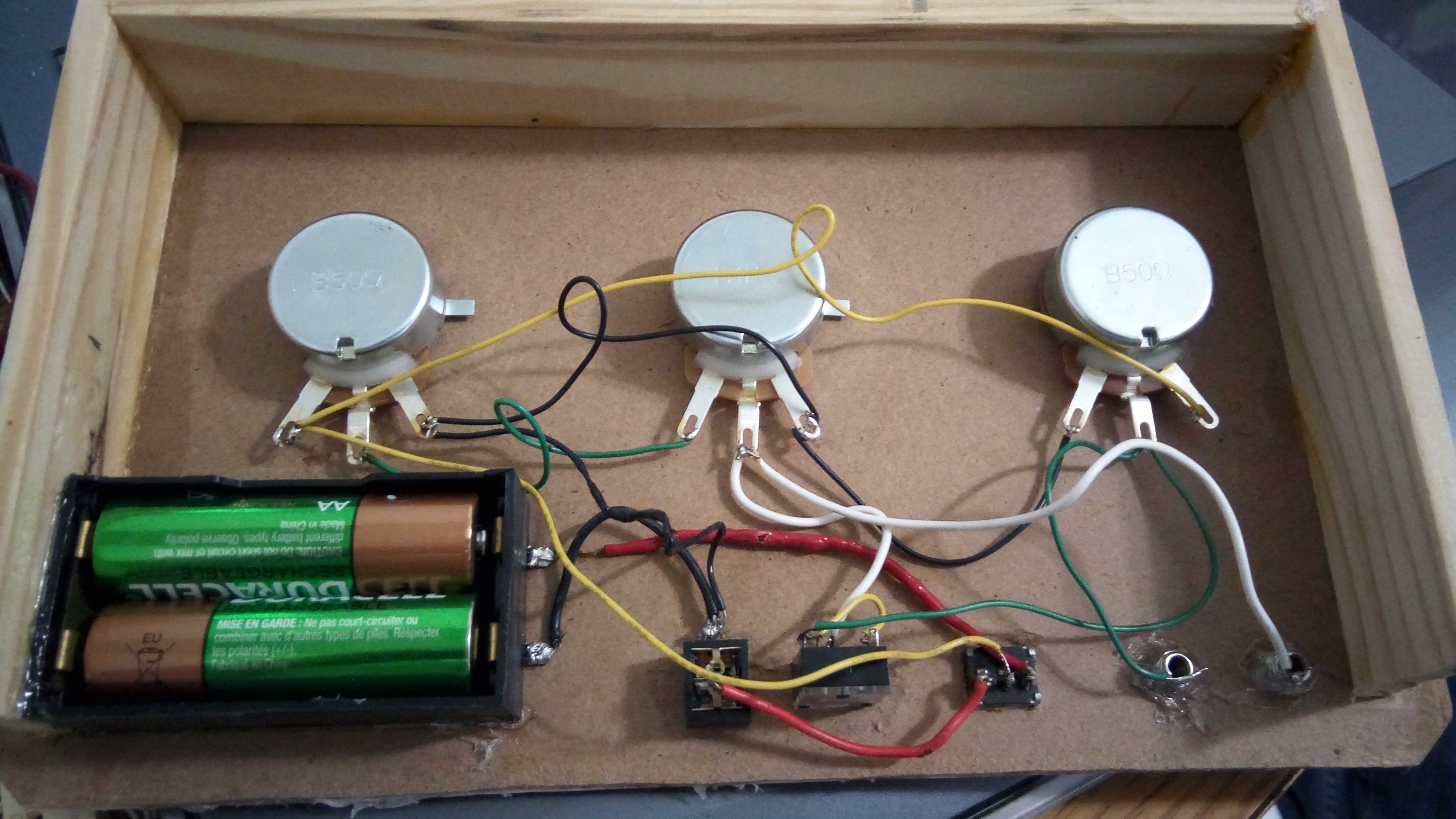
The face of the computer with the gauges was laminated and glued to wood. I thin added side walls to mount in the pencilbox. I also 3d printed a battery holder for AA batteries. Again this is wired for either the voltage or the audio input. The finished bottom looks like this.
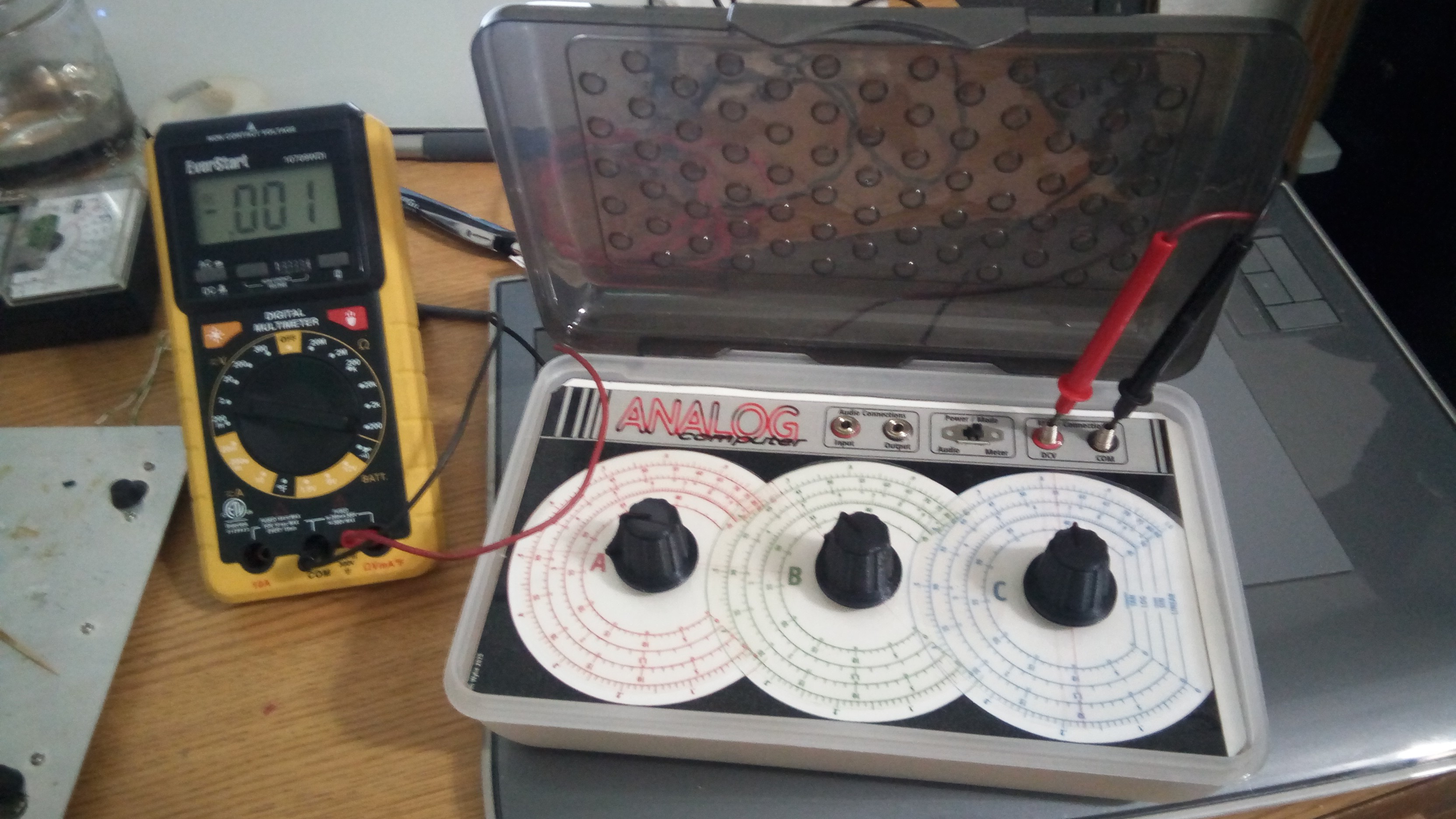
And that's it! There's a lot to be said about the actual potentiometers used. The tolerance should be less than 5% in order to get fairly accurate results. Using 20% tolerance means that between the 3 pots, your error could be too large to be useful.
 I included in the files the gauge section without any numbers as well. This allows you to mark the gauges specific to your pots so that they're more accurate.
Discussions
Become a Hackaday.io Member
Create an account to leave a comment. Already have an account? Log In.