 Andrey Bykanov
CONCEPT
Maxim Integrated MAX1978 was chosen as the core of the controller, this is a highly integrated controller for Peltier thermoelectric modules, there is a PWM controller, chopper op-amps, power output switches, reference voltage source and more. It is a bipolar controller, produces both heating and cooling mode at the same time. There is no difference between the ambient temperature above or below the box temperature, the box temperature will be stabilized in any case.
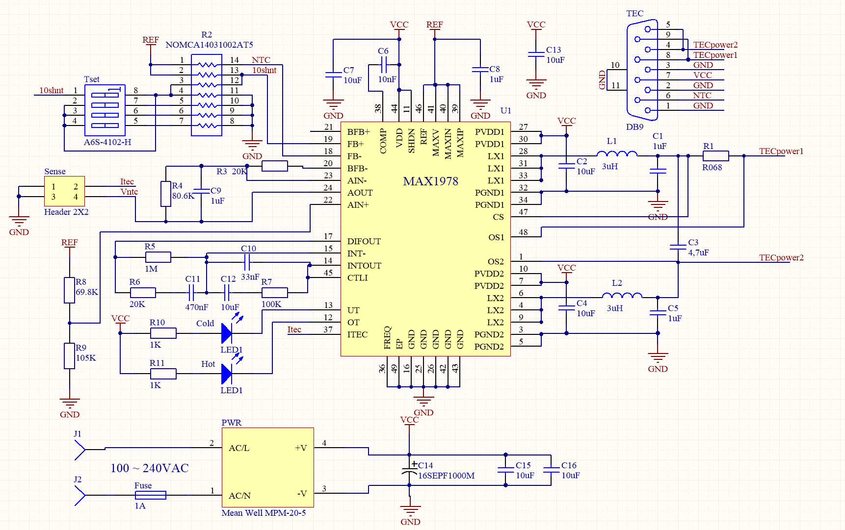
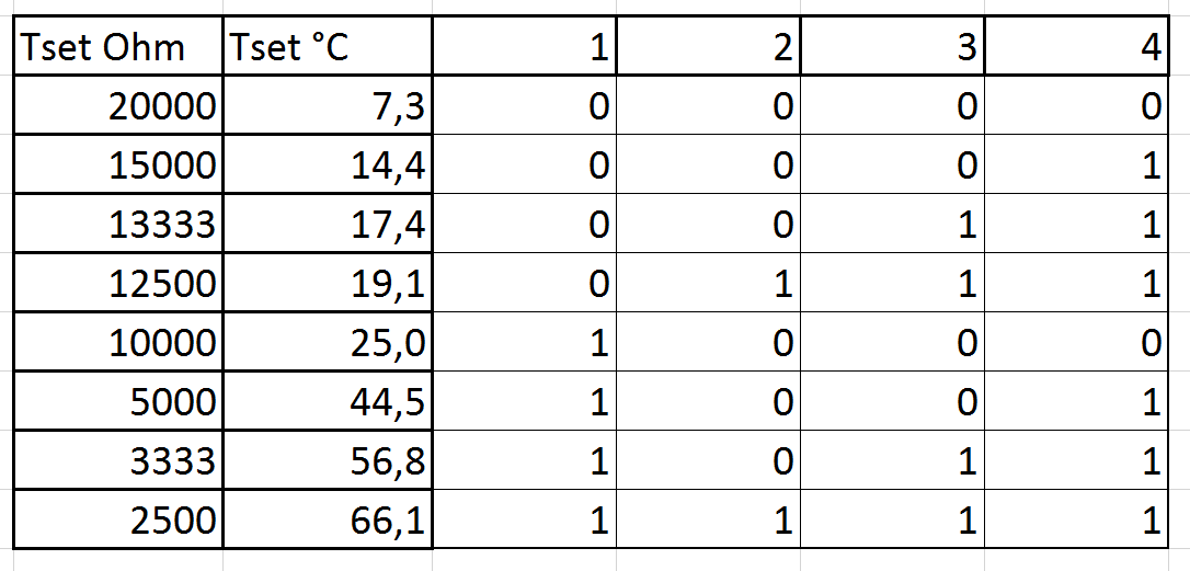
The feedback circuit is made on a miniature NTC-thermistor Murata NXFT15XH103FA1B150 connected to a programmable bridge circuit, assembled on a precision set of resistors Vishay NOMCA14031002AT5. Switch allows you to program bridge resistance, this switch called Tset. The switch allows setting the comparator resistances of 2.5 kOhm, 3.3 kOhm, 5 kOhm, 10 kOhm, 12.5 kOhm, 13.3 kOhm, 15 kOhm, 20 kOhm, which provides 8 points of stabilization temperature in the range from + 7.3 ° C to + 66.1 ° C.
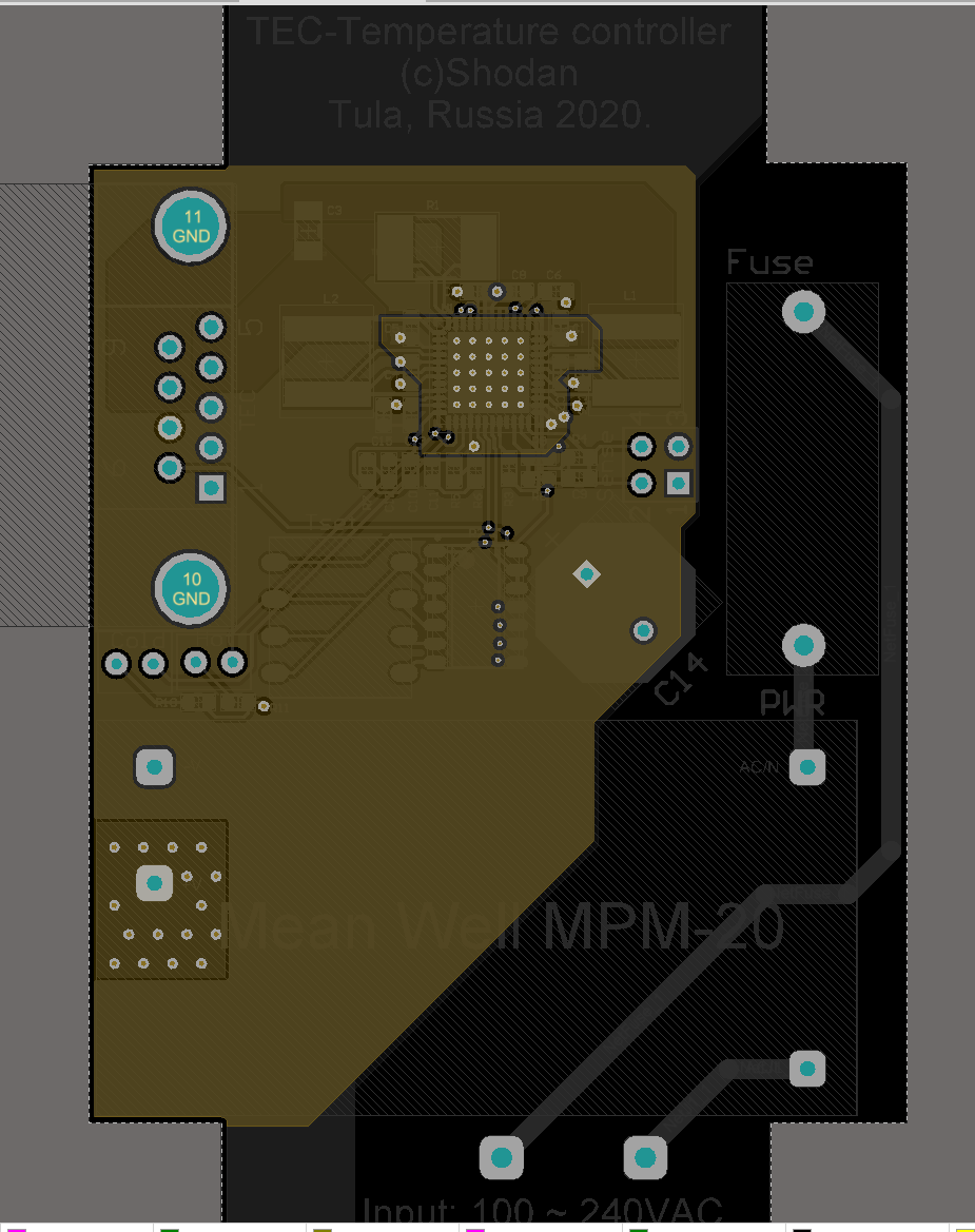
A Mean Well MPM-20-5 20 W was used as a power source.
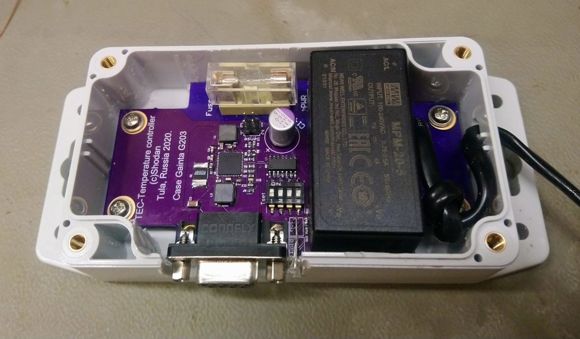
TEC module, NTC thermistor and optional cooler are connected to the DB9 connector. Please note of the DB9 connector, the TEC pins paired to provide 3A current flow. The board itself is packed into a series of Gainta G203 cases.
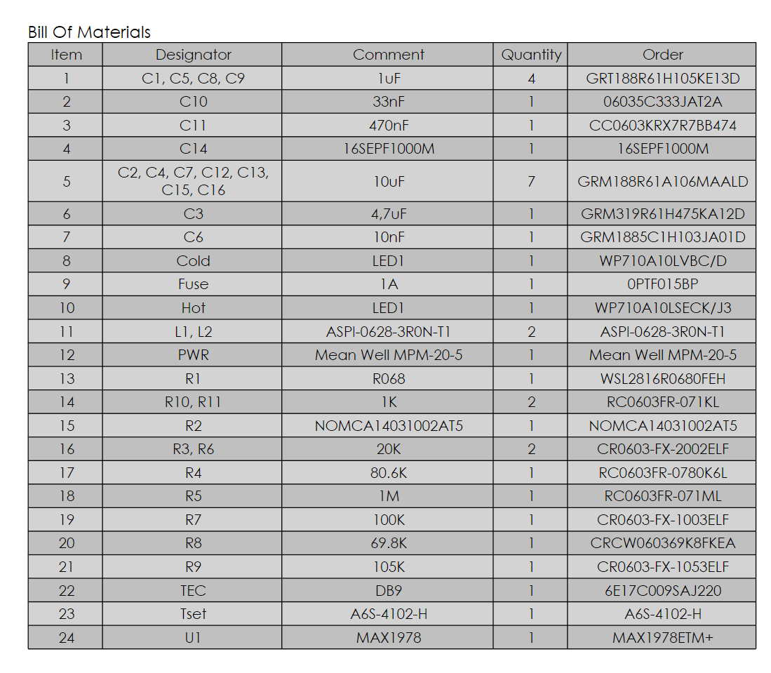
All components in 0603 size except the 4.7μF capacitor, 68mΩ resistor and chokes.
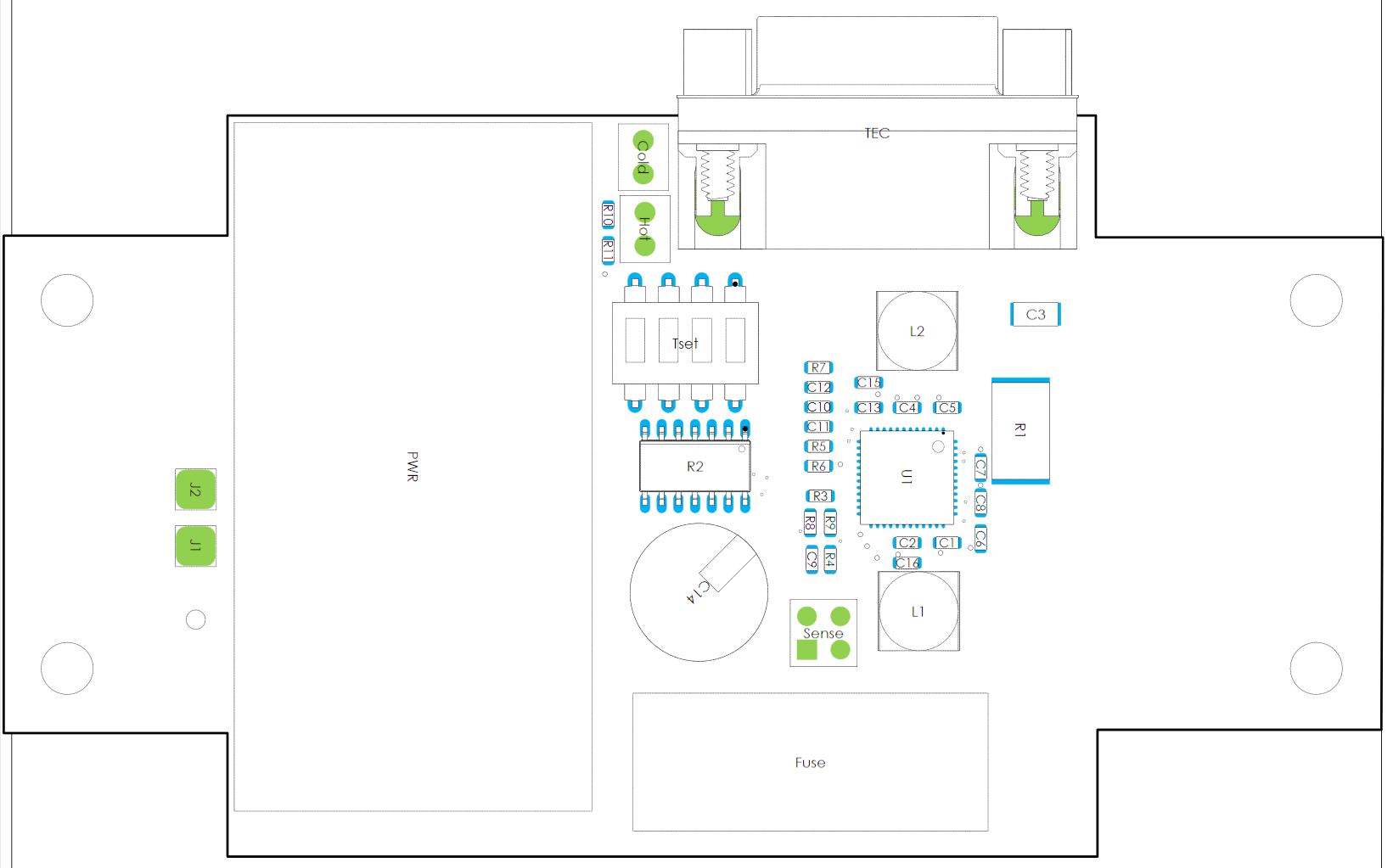
The controller board is routed in 4 layers to ensure better heat absorption from IC.


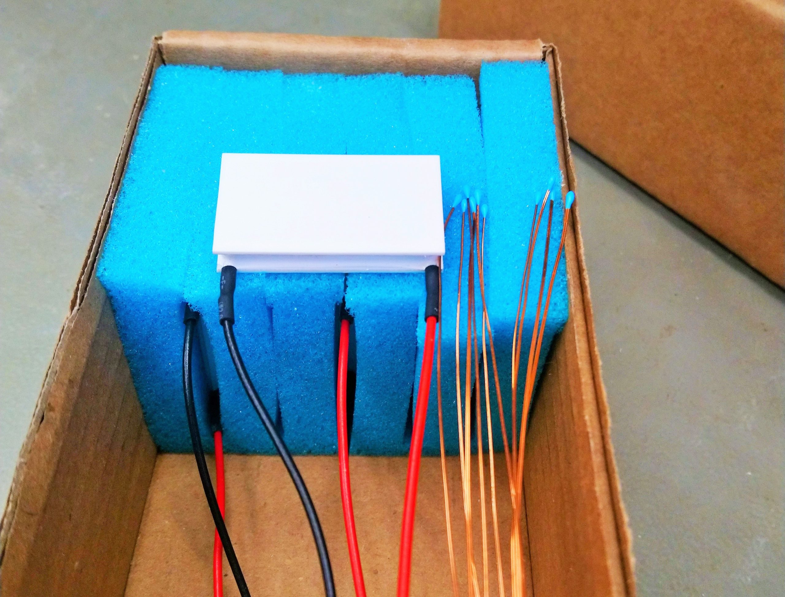
Peltier modules are low-voltage, is Cryotherm TB-48-1.4-2.5 with a flange sealing to extend life.
CHAMBER
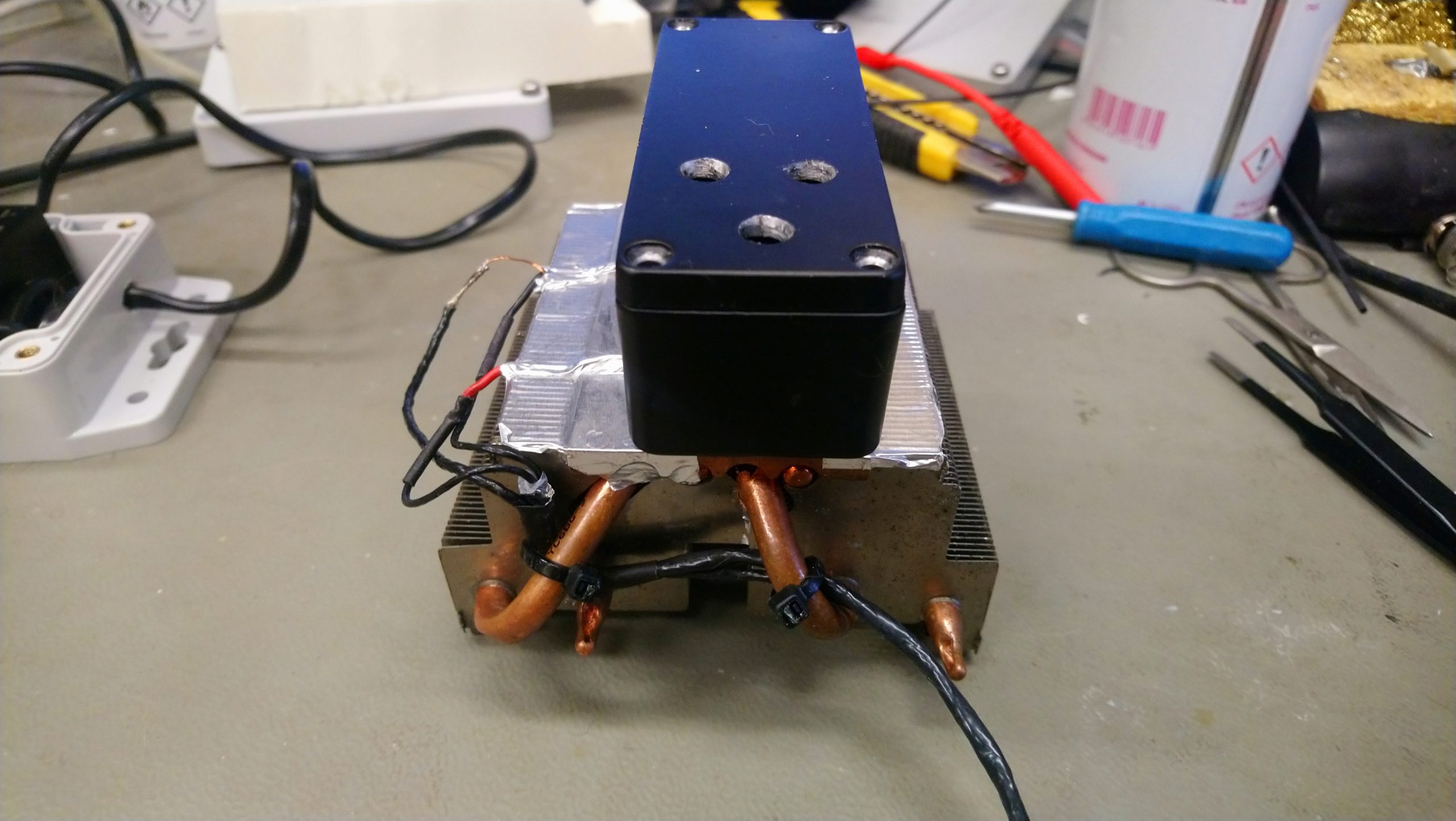
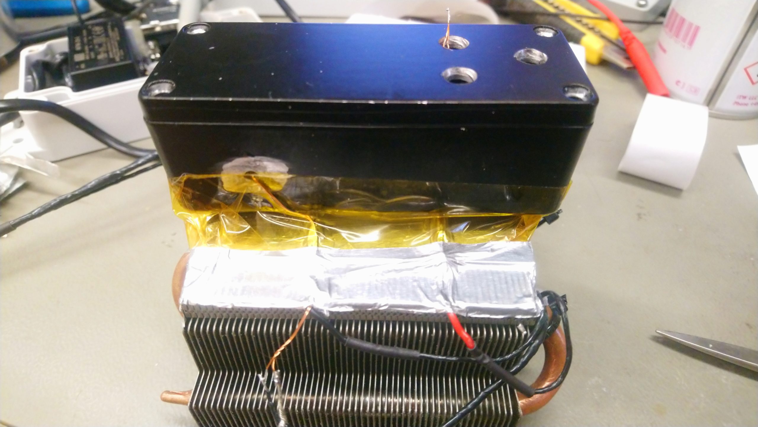
I use old CPU heatsink without fan with 4 heat pipes. Two holes drilled in it. Of course, one heat pipe suffered in this process, The holes were threaded for screws. The same mating holes without thread drilled into chamber.
Paint was removed from the bottom of the box with a metall brush. Then I put together a classic way: CPU heatsink - Arctic Cooling MX4 - Peltier - Arctic Cooling MX4 - Chamber. And all was pulled with nylon screws from AliExpress to minimize parasitic heat transfer through the screws.

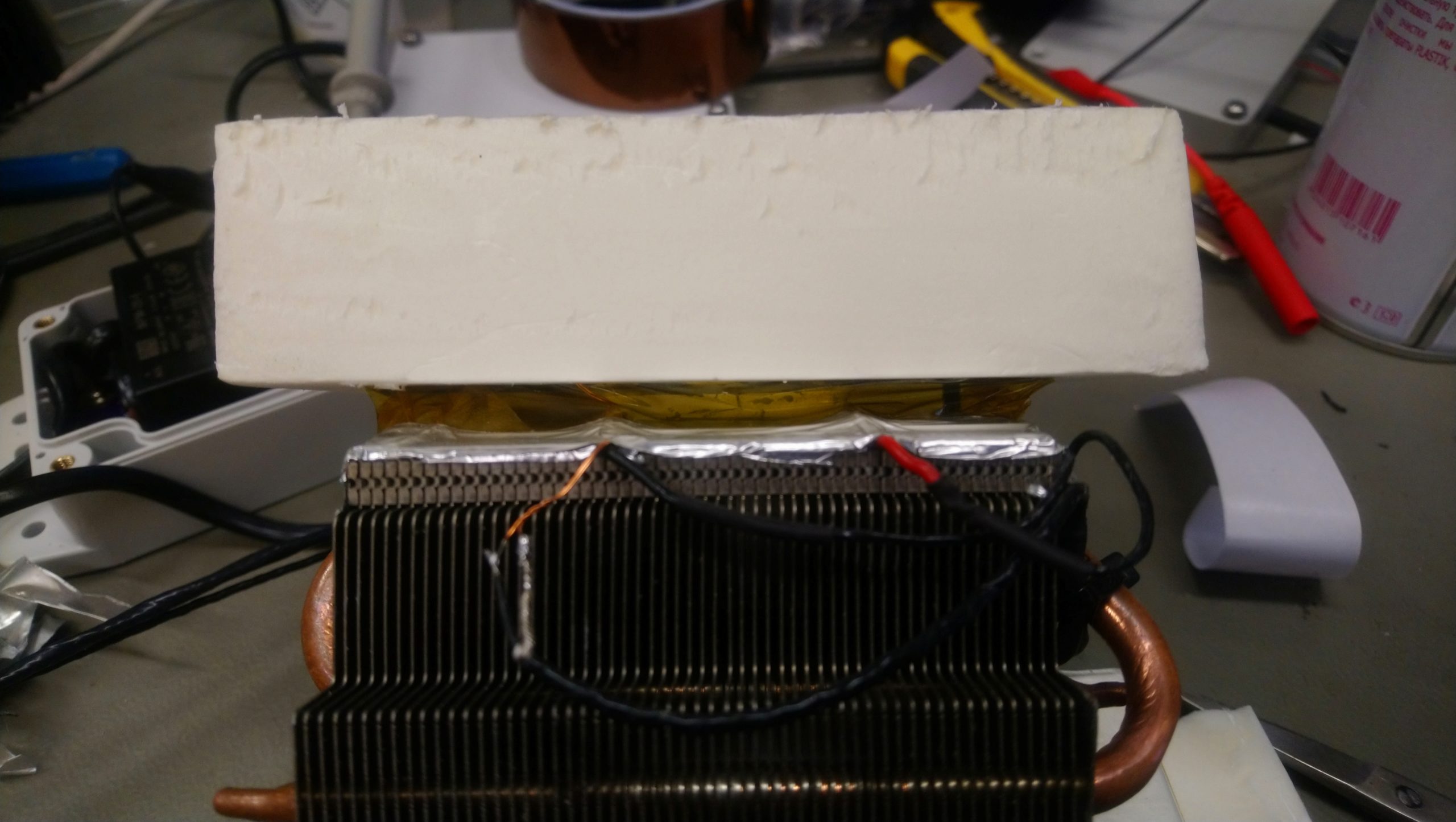
A heat shield was cut from XPS (Extruded Polystyrene Foam).
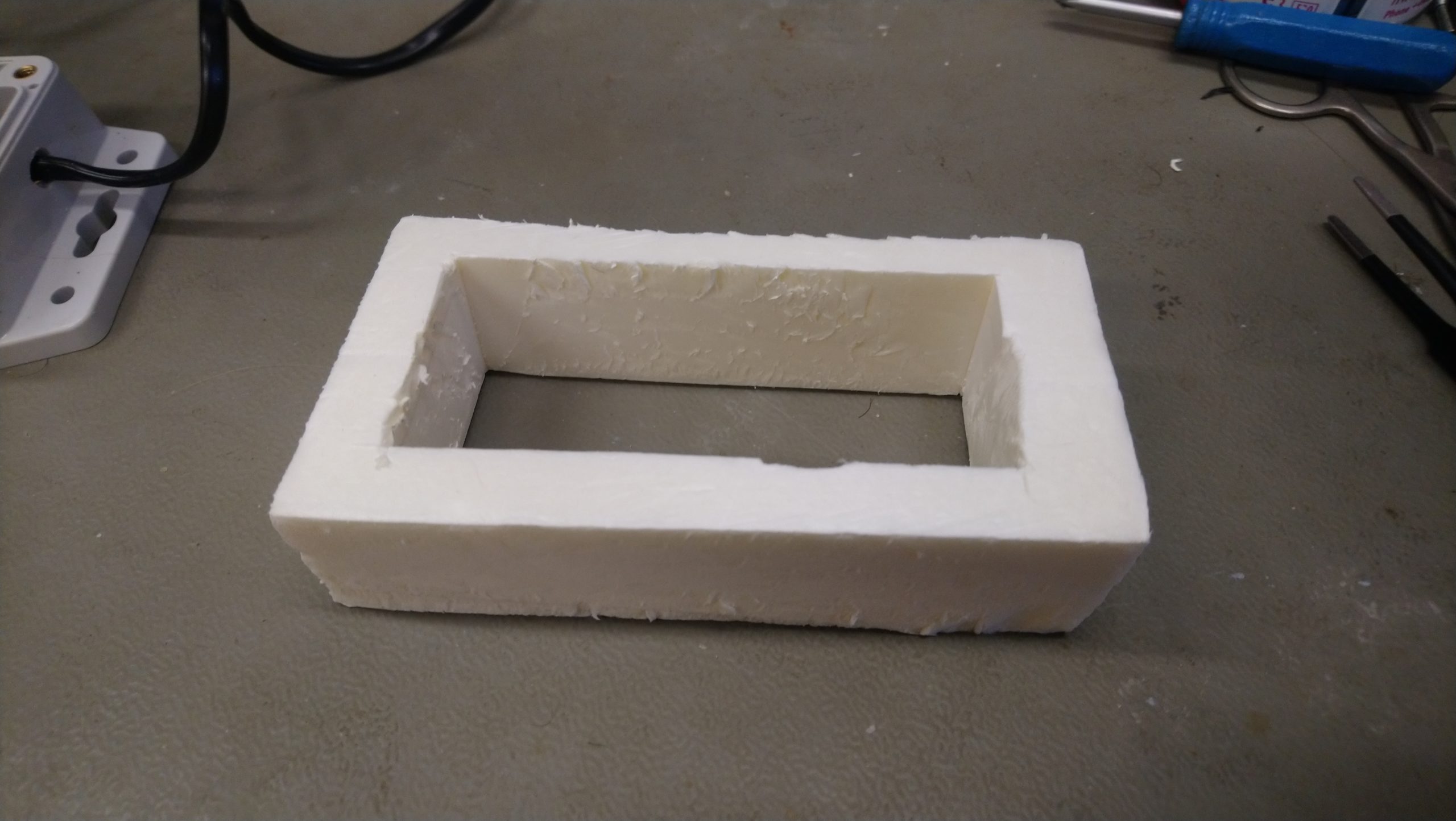
It should fit snugly over it and not slip. Important that it does not touch the CPU heatsink to decrease heat transfer. Heatsink slots need to be closed with aluminum tape to do air does not circulate through them. And perimeter gap of the flange, need to be closed with thin polyamide tape to prevent wind flow between gap.
Thermal sensor need to be attached to wall. I have tried several crimping options. As you can see in the picture, at first I fixed it to the floor of the box.
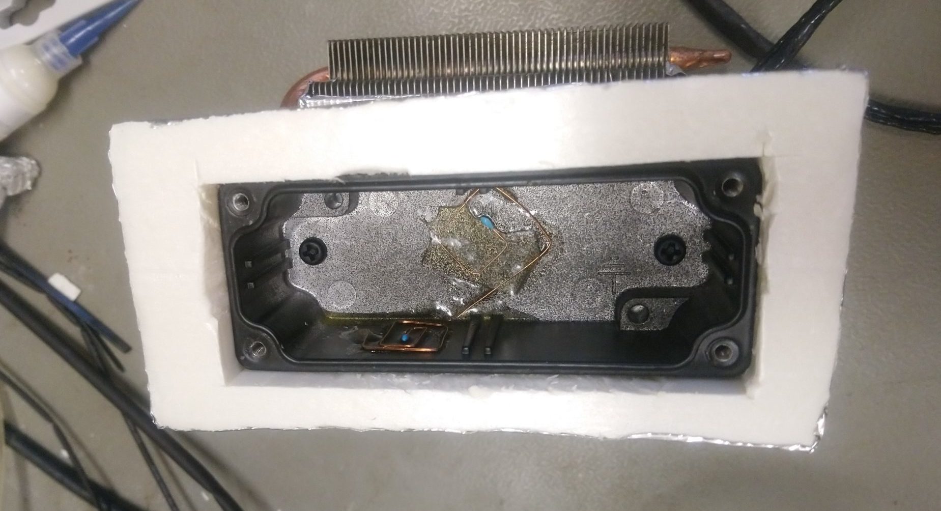
But i was wrong, that is failure way, because that way is stabilized the temperature only of the floor in box. Because wall temperature is slightly different. As a result, the still air temperature be dependent on the external temperature, at least +26...+70mK/K.
This problem can be solved by mounting the sensor on wall of the box. Coefficient down to -7.8mK/K.

Note: Amber line is still air in the chamber. Blue line is the ambient test temperature.
I twist the sensor leads with the "G" form to minimize heat transfer to sensor through leads and fill it with epoxy glue.
Testing under natural room conditions (65 hours):
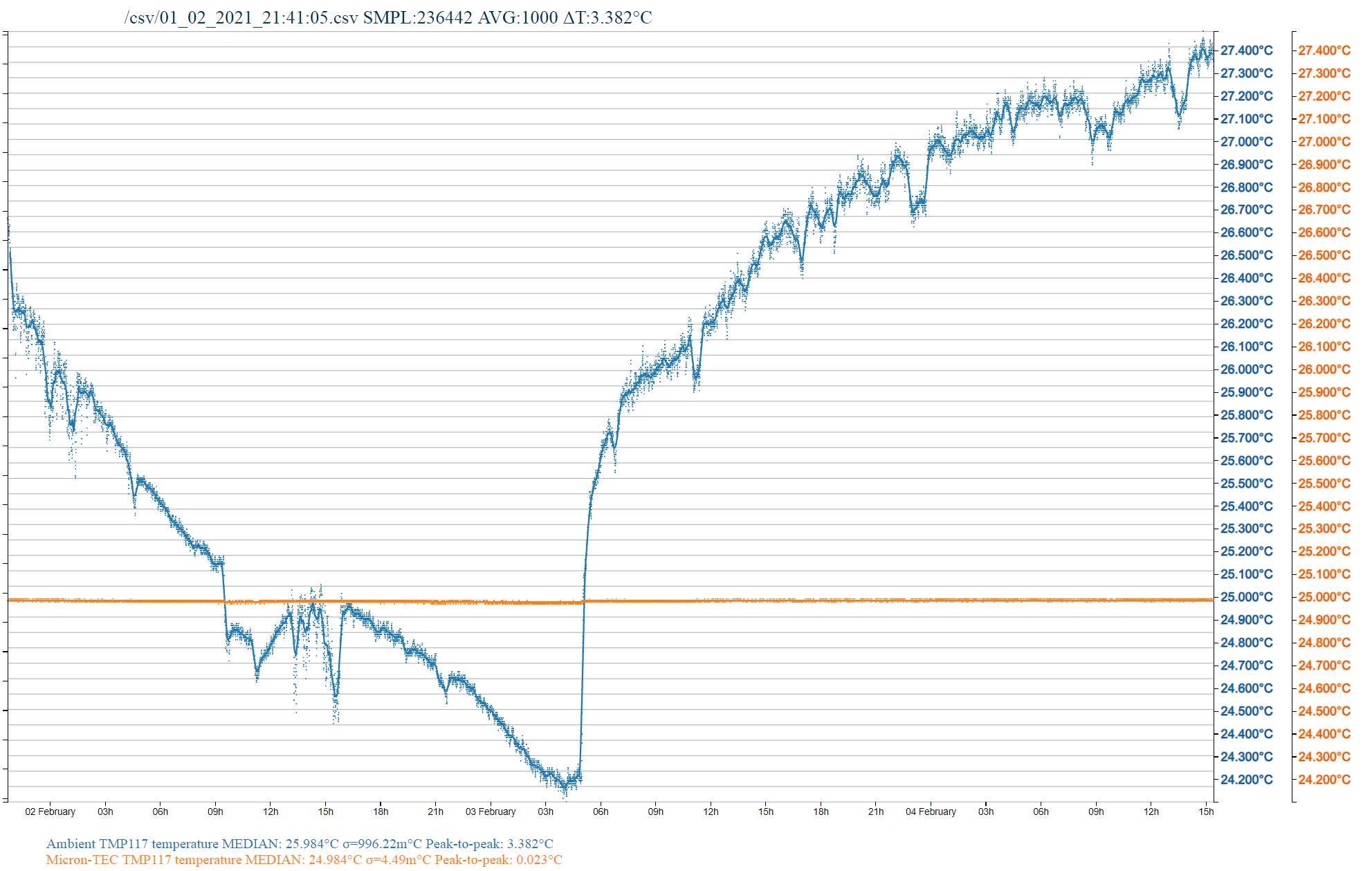
Chamber temperature is very stable and does not drift. Peak to peak temperature drift in the chamber was only 0.023 ° C, whole 65 hours test.
Power Test:
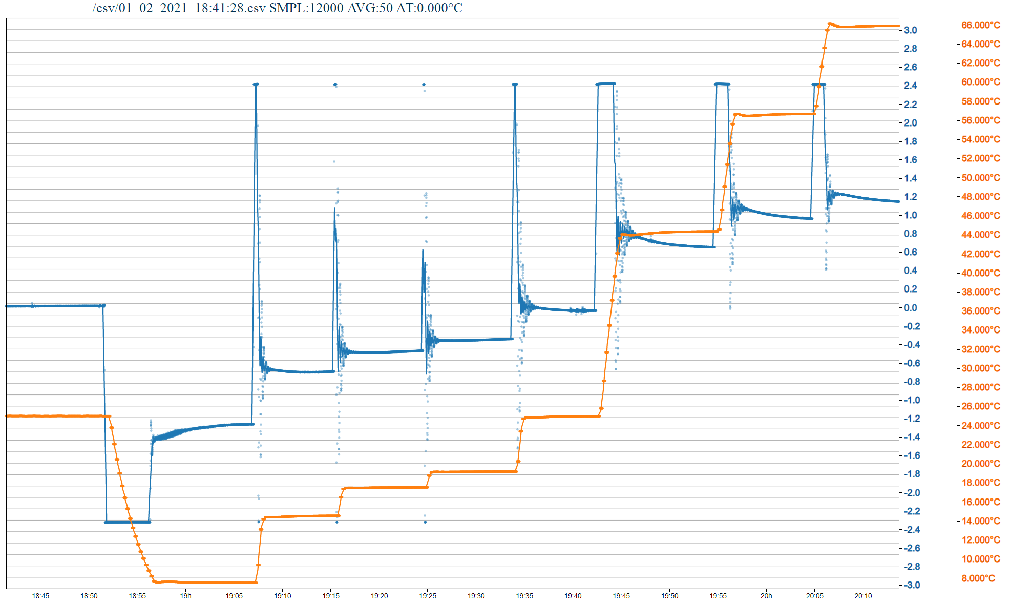
Blue line - TEC current. Measured voltage on Itec pin and calculated to Amps trough formula into MAX1978 datasheet. (1.5V DMM null offset + MX+B math where M=1,84 B=0)
Amber line - TEC box temperature measured with TI TMP117 sensor.
Note: Positive current - warm-up Peltier mode.Negative current - cooling Peltier mode.
All eight values of Vishay NOMCA bridge (Tset) has been tested:
Start Tset=1-0-0-0=25°C (bridge res.10K)
18:52 Tset=0-0-0-0=7.3°C (bridge res.20K)
19:07 Tset=0-0-0-1=14.4°C (bridge res.15K)
19:16 Tset=0-0-1-1=17.4°C (bridge res.13.3K)
19:25 Tset=0-1-1-1=19.1°C (bridge res.12.5K)
19:34 Tset=1-0-0-0=25.0°C (bridge res.10K)
19:43 Tset=1-0-0-1=44.5°C (bridge res.5K)
19:55 Tset=1-0-1-1=56.8°C (bridge res.3.3K)
20:05 Tset=1-1-1-1=66.1°C (bridge res.2.5K)
* Very high speed temperature ramps, it means i can use much more BOX/DUT thermal mass.
* Test on Tset=7.3C shows -1.3A current, it means system have power reserve for cooling mode, that very good!
* Test on Tset=66.1C shows +1.1A current, it means system have power reserve for warm-up mode, that very good!
* Nice ramp-to-stabilize regions(amber line) without significant overshoot, it means my fast PID compensating method(calculate R7 and increase C11 after move NTC to wall) not too bad....
* Yup, its little current ringing(blue line) on ramp-to-stabilize region, but not too bad... maybe i'll try fix it later.
PID
Time to black magic !!!
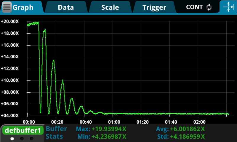
Since we have placed the thermal sensor far from the Peltier, the reference circuit going decompensated.
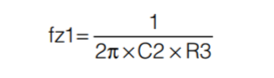
New thermal resonant frequency need to be measured on Itec pin and calculate it with formula from the datasheet:
Let's calculate new resistance value. My new resonant frequency is 31 mHz. We get that C12 = 10uF and R7 = 500k values for new resonance frequency of 31 milli-hertz. You will have different values, since the resonance frequency will be different. Makes sense to take R7 larger, up to 2-7 times more than the calculated value it will increase the stability of the system.
After that, we can observe floating-damped oscillations with a slightly different frequency:

But they will not go to zero. This can be corrected by adjusting the chain R6, C11. I increased C11 from 470nF to 2.2uF and got the following result:
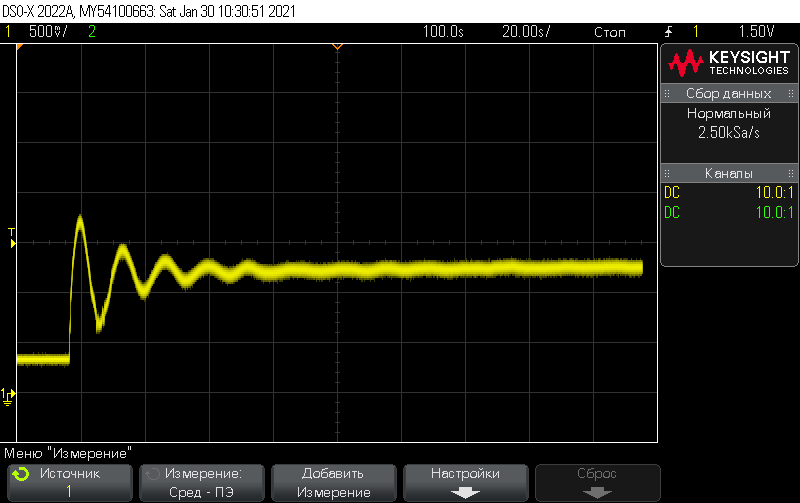
Much better!
All wires of DB9 socket must be shielded to decrease noise and EMI injection.
Important note: NTC sensor must be shielded separately!
The consumption of the device with a small temperature difference is small. With a differential of 3 ° C (Troom = 28 ° C, Tset = 25 ° C), the consumption was less than 5 VA.
The End!
