I started work on this about two years ago when the clock stopped picking up the temperature sensor's signal. I searched to see if anyone had created a library for it, but did not find any. A search for the transmitter's FCC ID did result in what appeared to be the original manufacturer's filing, including a block diagram, signal timing diagram, schematic, and other documentation.
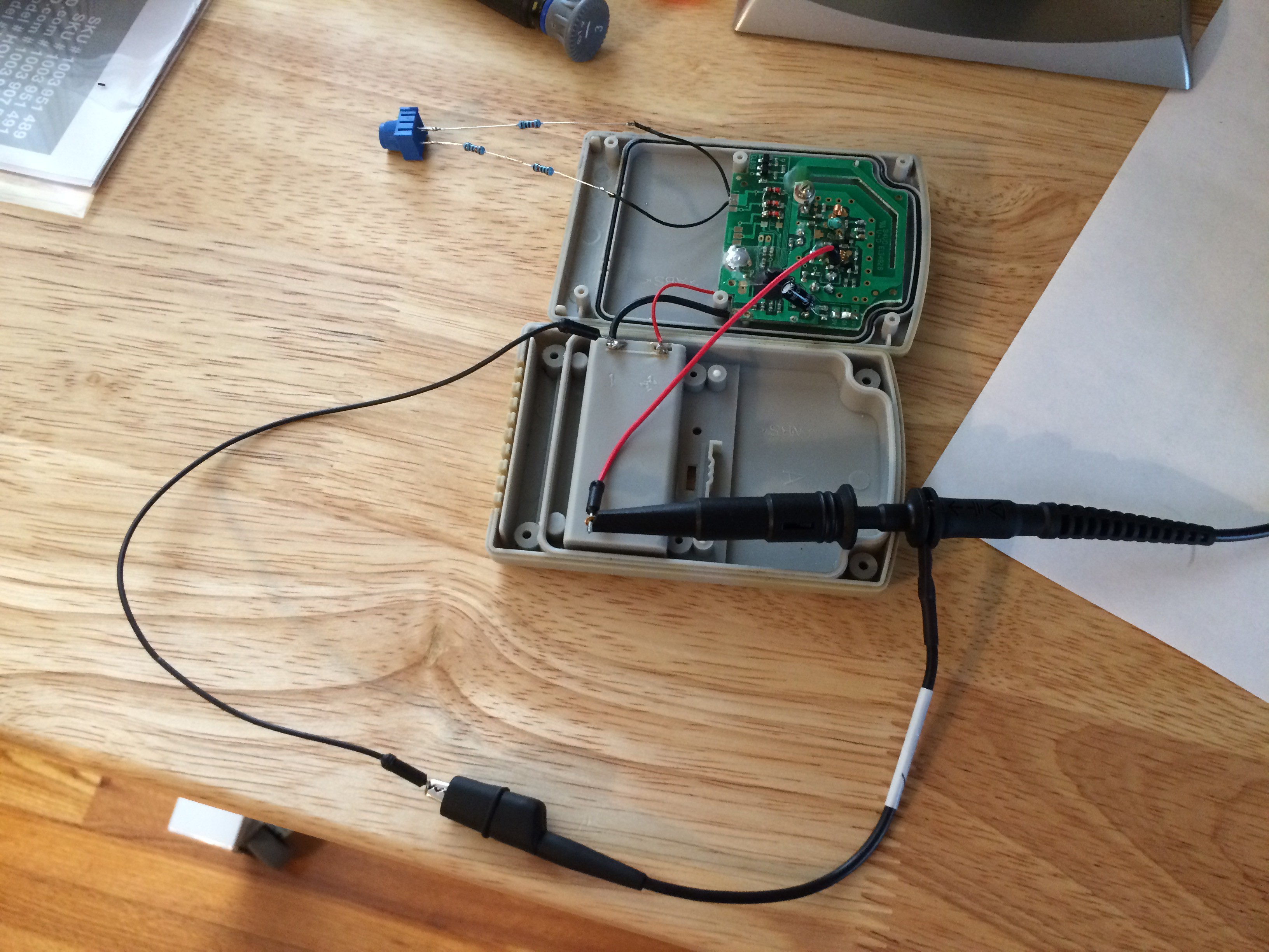
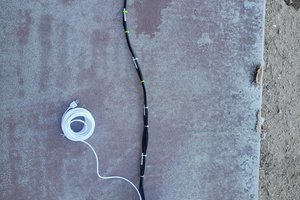
Since there were no existing libraries that I could find, I took advice from some forum postings of people in a similar position as myself and began to make recordings of its transmissions. I created a spreadsheet in LibreOffice Calc where raw binary transmissions and their corresponding temperature readings could be stored and visualized. I then found a place on the transmitter's PCB where I could solder a wire to capture its signal with my oscilloscope. At the time I only had a DSO138 oscilloscope so this quickly became frustrating and the project was shelved.
My father got me a Tektronix oscilloscope for Christmas, which didn't arrive until earlier this month. It renewed my interest in this project and has allowed me to easily capture and record the signals from this transmitter.
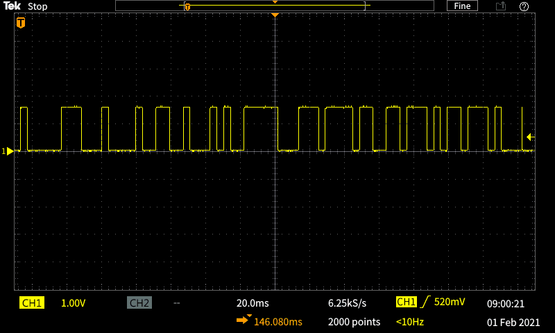
The documentation from the FCC site helped me make sense of the signals. It told me the device used on-off keying (OOK) and binary-coded decimal (BCD) to encode the temperature. With this information, I was able to quickly locate the temperature. After making additional recordings with the "channel" switch in different positions the channel ID became apparent as well. To isolate the battery low indicator, I powered the transmitter off of my bench power supply and made a few recordings with the voltage set to about 2.27 V. During this time I also noticed there appears to be a 6 bit randomly generated ID that changes anytime the transmitter is reset.
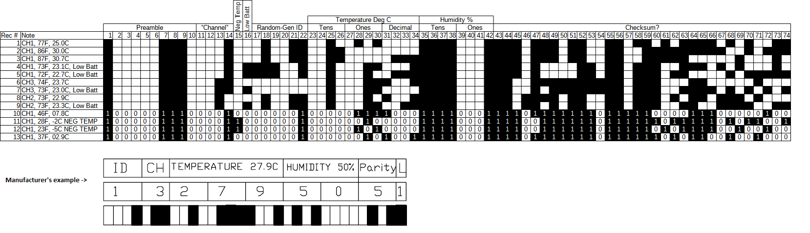
It was apparent after the first few recordings that what the transmitter was actually sending differed greatly from the example provided by the manufacturer in their FCC filing. Despite this, I went with what the example said and assumed the 8 bits following the temperature were a placeholder for humidity even though my transmitter has the humidity sensor omitted. Below is a picture of my Calc spreadsheet at this point in time with the manufacturer's example below it for comparison:
Seeing that I only had 32 bits at the end to figure out, I assumed this was a CRC checksum and began to run CRC RevEng on the last four transmissions to figure out what it was. After trying it with many different parameters and omitting different combinations of bits off the front of the signal, I began to suspect that part of the checksum was not a CRC at all. This suspicion was further fueled by the difference in appearance of the left and right halves of the checksum data.
I returned to Google and found where other temperature probes included a XOR of the payload data as part of their checksum. After staring at my spreadsheet for some time, I found where my transmitter contained a XOR in its checksum as well. With this new discovery, I arrived at the current version of my spreadsheet:
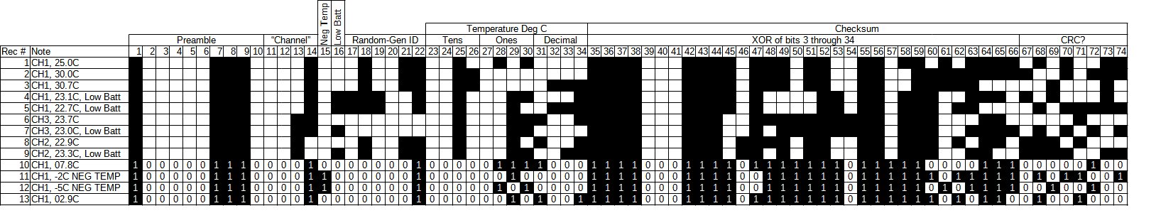
I again proceeded to run many combinations of data and parameters through CRC RevEng, but I have not yet been able to figure out the CRC.
 Tim Rightnour
 ToniTheAxe
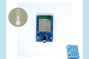
 Daphne
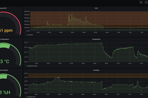
 Grégory Paul
hey Ty, take a look at fcc I’d OQH-000000-06-007 another chungs TX the timing diagram on that still isn’t quite the same as what your looking at but it is much closer