Close
0%
0%

Solid state DC speaker protection.

A small board to protect your speakers from unwanted DC-bias. Two N-channel mosfets are used instead of an expensive relay.

Public Chat
Similar projects worth following
Classical speaker protection circuits use a relay to interrupt the speaker connection when a DC-bias is detected. The problem with relays is that they are really bad at switching DC currents. Most relays which specify a DC interrupting voltage/current are large and rather expensive. You can use smaller under specified relays and hope that they burn up when switching off. But that is rather sketchy.

In my search for a better solution to protect my precious speakers I came across Rod Elliotts website:
https://sound-au.com/articles/mosfet-relay.htm
He did amazing research on how to build a solid state relay using mosfets in various ways.
Based on his research I made a simple speaker protection using two N-channel mosfets. This reduces cost and maintenance in your amplifier.

Making a solid state relay using mosfets isn't particularly easy.
A mosfet is turned on by applying either a positive or negative voltage (depending N/P-channel) between their gate and source. But when using them as a relay, the voltage applied to their source can vary widely. From positive to negative in quite a large range. Especially in amplifiers where I want to use them their source voltage is constantly dancing up and down.

So just applying a fixed voltage referenced to the same supply ground as the source you are trying to switch off is not possible. Your gate-source voltage would constantly change making it impossible to switch on the mosfet constantly and not damage it.
What we need is a separate voltage source which is fully independent from the one we are trying to switch off. This way we can connect the "ground" reference of this voltage source to the source of the mosfet. That way the gate voltage of the mosfet is referenced to the varying source voltage and thus fixed.

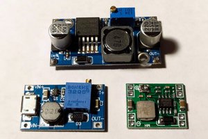
One easy option to have a separate voltage source, is to just make a second supply using a battery or a transformer. But just to drive some mosfets this is a rather expensive solution. And batteries get depleted meaning you will have to replace them.

Rod Elliott explores many options to make an isolated driver to control the mosfets. From using an isolated DC-DC converter to capacitive coupling. Many of these are interesting and good options. But the last one that was added really had my attention. It uses one single chip from Silicon Labs that does everything for you.
The Si8751 is rather cheap and only requires few external components. With this chip the only thing we need is some additional circuitry to do the detection of a DC-bias and we are set!

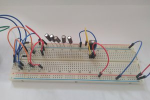
On the internet there are a lot of detection circuits available. After some research I've settled for one with a diode bridge and a low pass filter. A simple transistor is used to pull down a 5 V signal once the DC-bias is high enough.

The low pass filter is dimensioned for a cut-off frequency of 0.16 Hz. This should be more than low enough for an amplifier with very low bass.

The following image gives a simplified representation of the circuit when a positive voltage is applied at the input terminals.

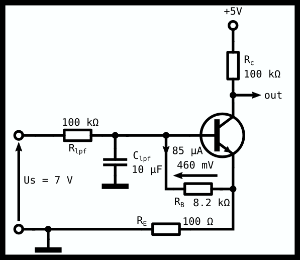
The base-emitter resistor determines at what DC-bias the transistor will switch on. Once there is 460 mV (I determined this experimentally) across its BE junction it fully turns on. The following equation is used to calculate the BE resistor:

We chose to turn the transistor fully on at 7 V. After some experiments I found that the diode voltage drop of the MB10F is around 0.5 V. As there are always two diodes conducting, we need to subtract 1 V before filling in Us in the formula. This results in a Rbe resistor of 8.3 kΩ or 8.2 kΩ E24-series.
If we have an 8 Ω speaker, there is around 875 mA flowing through the speaker. This gives a dissipation in the speaker of around 6.125 W. This switch off point might be too low, but we'll see what it gives in practice.

ampdcprot-1.pdf

KiCad Schematic

Adobe Portable Document Format - 34.01 kB - 02/19/2021 at 17:20

Preview
Download

  • Doing some measurements

    Tijl Schepens02/28/2021 at 15:45 0 comments

    My initial measurements show that my calculations are off because of some wrong assumptions.

    From the datasheet of the NSS40201 I assumed that the Vbe turn on voltage would be 0.7 V. But that is a typical value with an Ic of 1 A. As we have only 50 uA flowing through Ic it is impossible to deduct the turn on voltage from the datasheet.
    After some basic measurements I found that the turn on voltage is around 460 mV. After substituting this in the formulas, the calculated values now match my measurements.
    Initially I calculated that the transistor would turn on at a DC-voltage of 9 V. But with the new Vbe voltage the calculated value of 7 V now matches the measured turn-on voltage of 7.115 V.
    This turn on voltage is the voltage that needs to be applied to the input of the circuit to get the collector voltage of the transistor below 0.3xVcc. This 0.3xVcc is the votlage at which the NC7SZ175 will reset its output and disable the mosfets.

    Another thing that could not be deducted from the datasheet is the forward voltage drop of the diode bridge. It only shows graphs with a forward current starting at 10 mA. It seems that at 100 uA like we have in our circuit the forward voltage drop is around 0.49 V.

    The Si8751 operates as expected. When setting the D-type flip-flop it turns on the transistors and when the flip-flop is reset the transistors turn off.

    I also did some measurements to see when the transistors get hot. At 2 A continuous current the transistors already get too hot to touch. It seems that the FDD10N20LZTM has a too high Rdson.
    So I decided to replace the transistors with the NTD6416ANL. This mosfet has an Rdson which is more than 3x lower and the price is acceptable. There are of course other transistors with even lower Rdson but they are expensive...
    Re-doing the measurements with the new transistor yielded that at 2 A the transistors don't heat up. At 4 A they get quite hot. But I stopped the measurement there as my clips started melting at this high current level O.o

    With my oscilloscope I measured how fast the transistors turn on. One channel is connected to the clock input of the D flip-flop while the other is connected to a second power supply which is connected to the switching mosfets. Once the mosfets turn on, they short the supply.

    The transistors start turning on after 190 us. After around 1 ms the transistors are switched fully on. Note that this measurement also includes the delay of the NC7SZ175 and not only the delay of the Si8751.

    For the next measurement I connected one probe to the IN-pin of the Si8751. The switching mosfets are connected to a power supply set to 30 V in series with a 330 Ω resistor. The probe is connected to the point between the mosfets and the resistors.

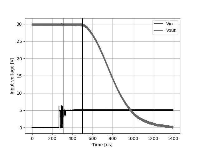
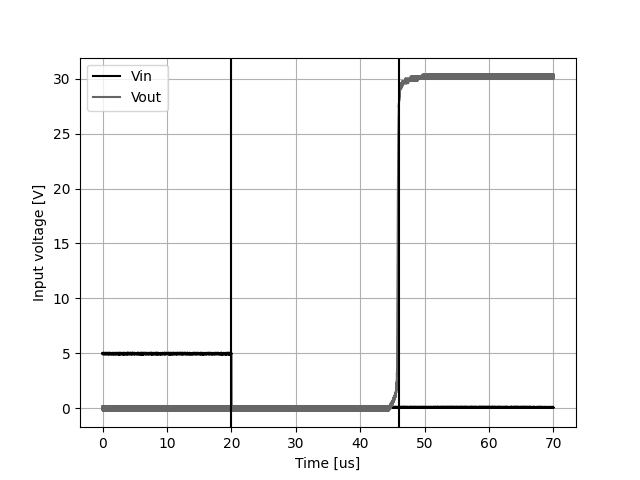
    This measurement yields that the Si8751 switches off the transistors after 26 us. This is in line with the specified maximum of 35 us in the datasheet.

  • Assembling the PCBs

    Tijl Schepens02/28/2021 at 10:08 0 comments

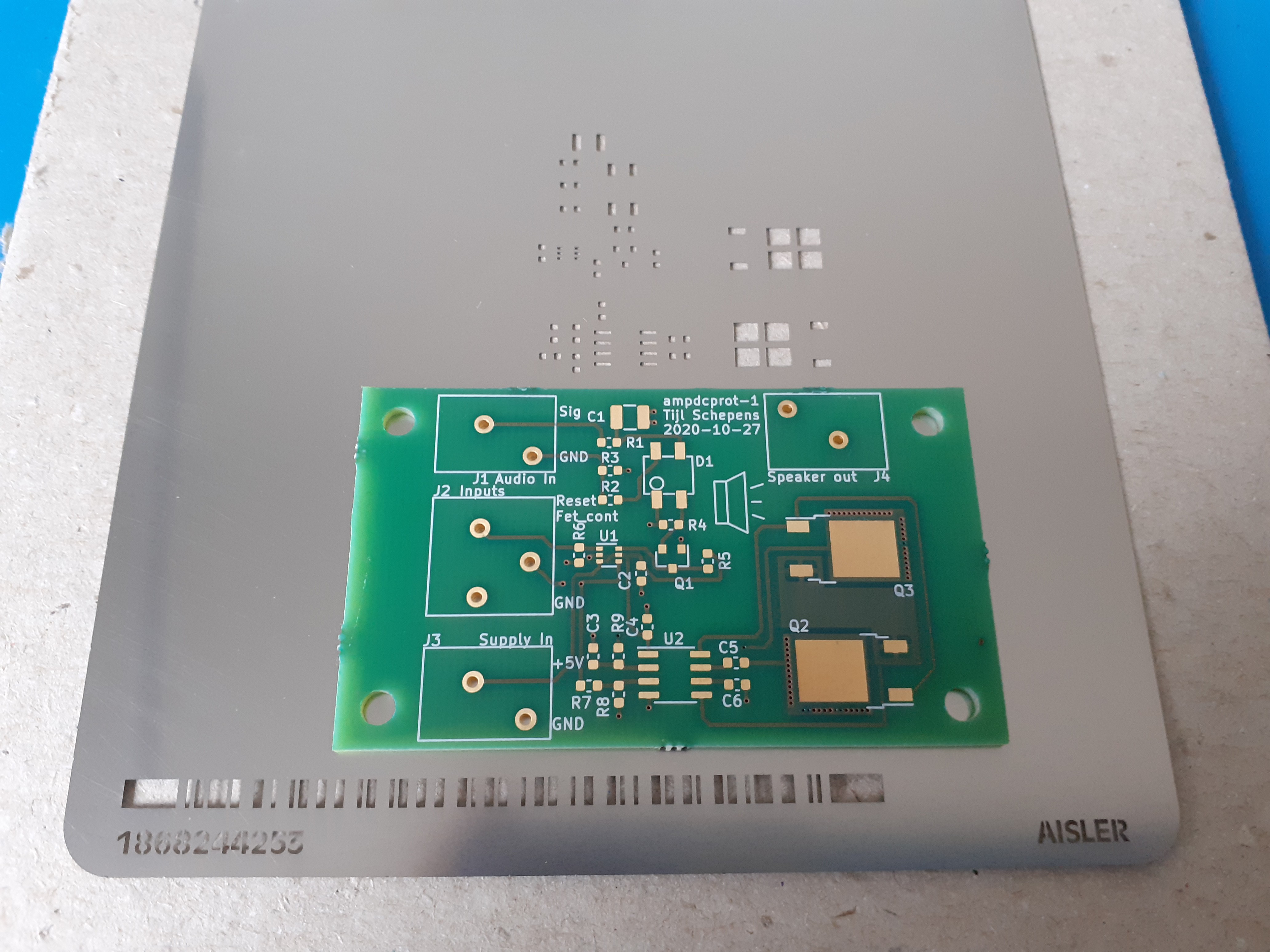
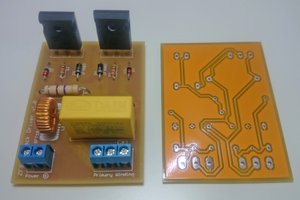
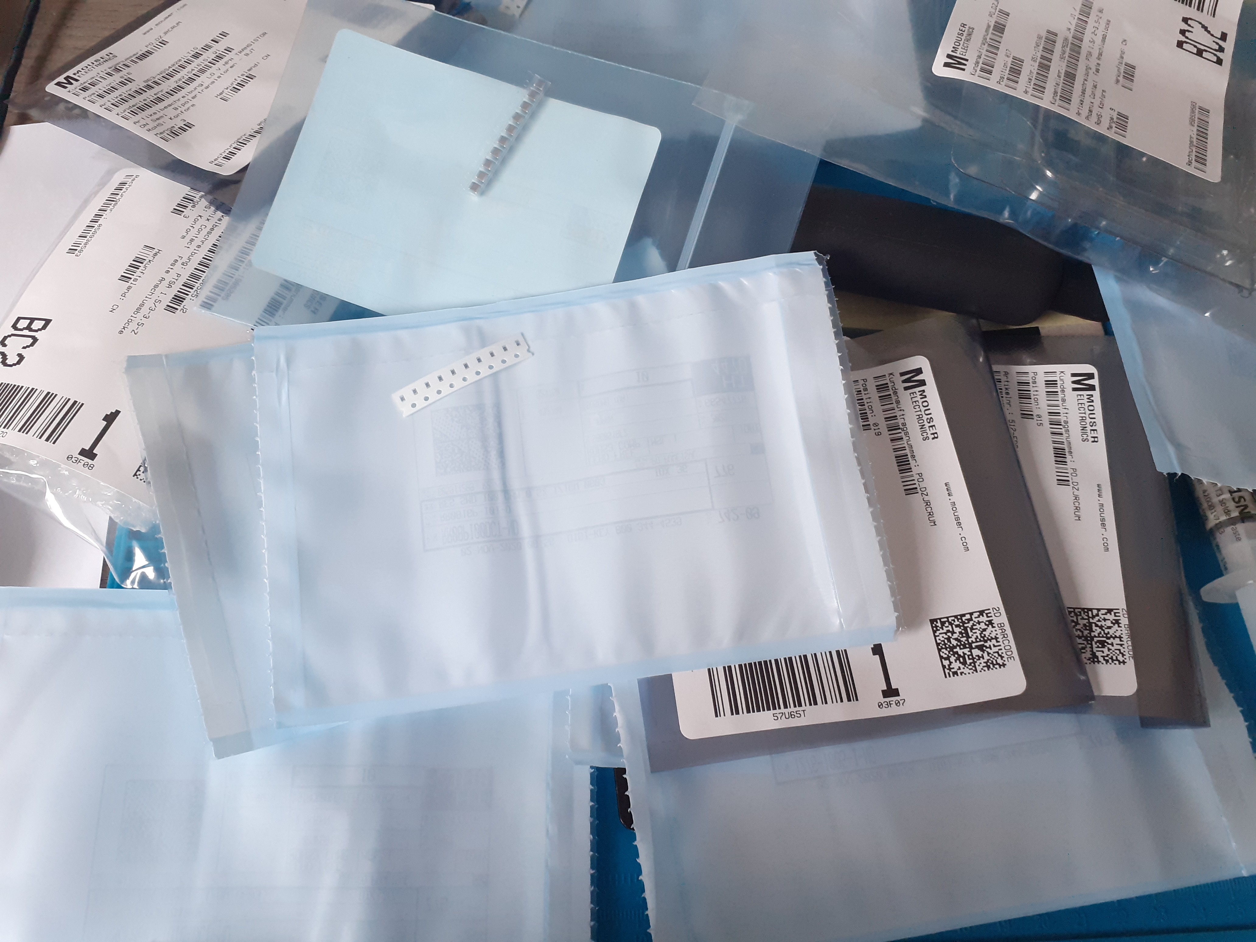
    After receiving the PCBs and components from the good people at Aisler we can start assembling!
    Using the stencil and a hot air gun it was quite easy to solder all the components. There are not small pitch or other difficult to solder components on the board.

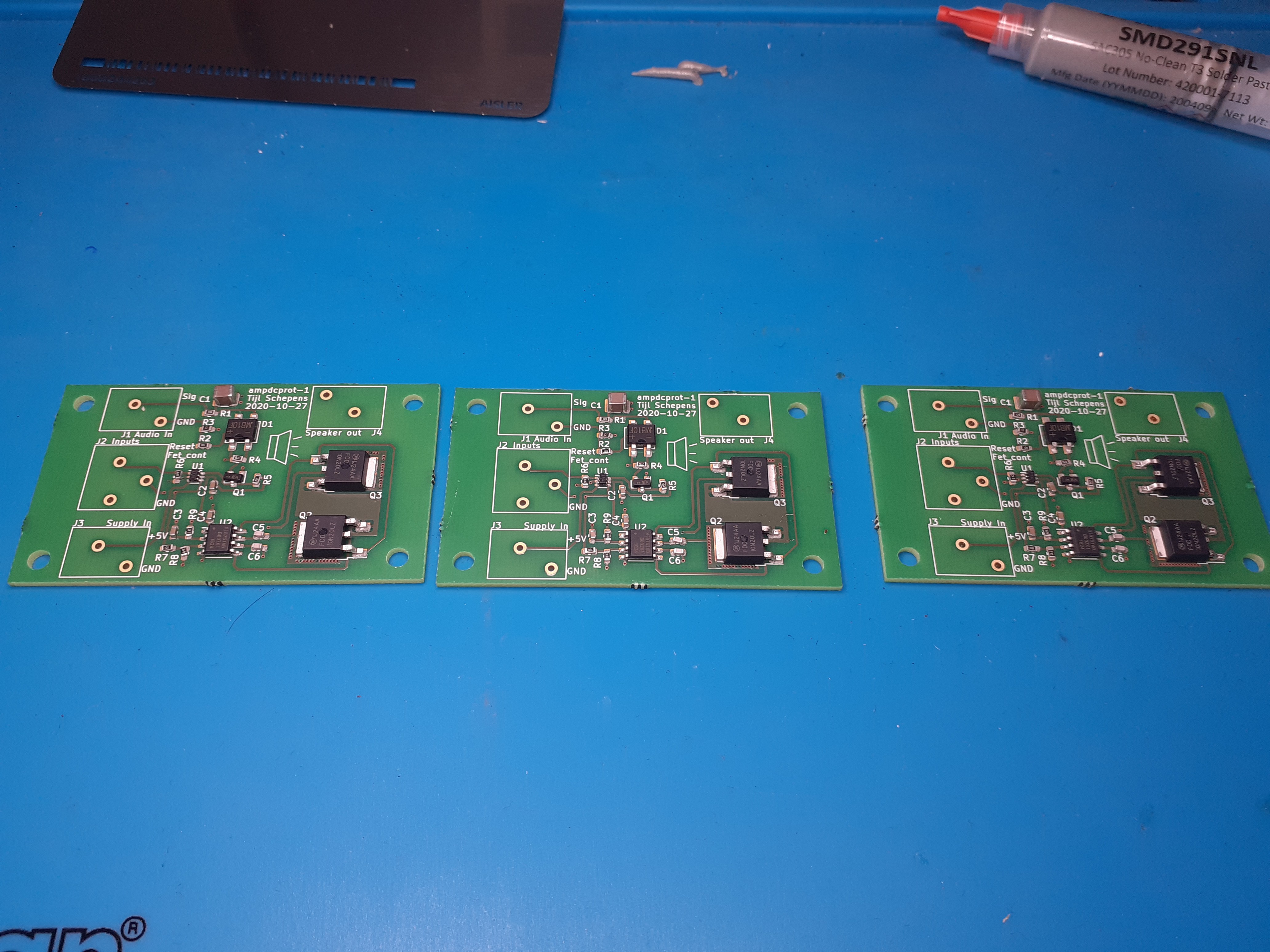
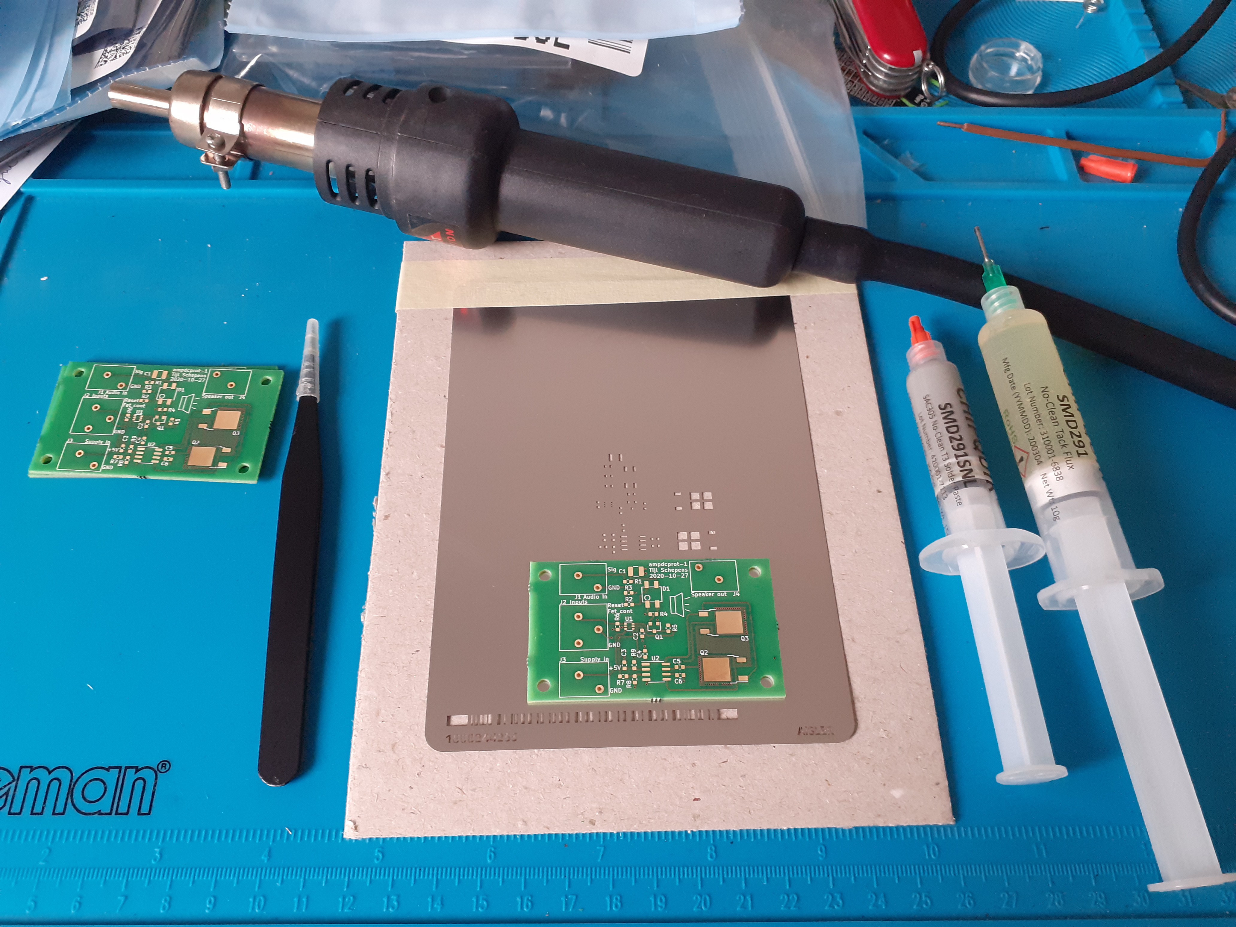
    Applying solder paste and reflowing everything.

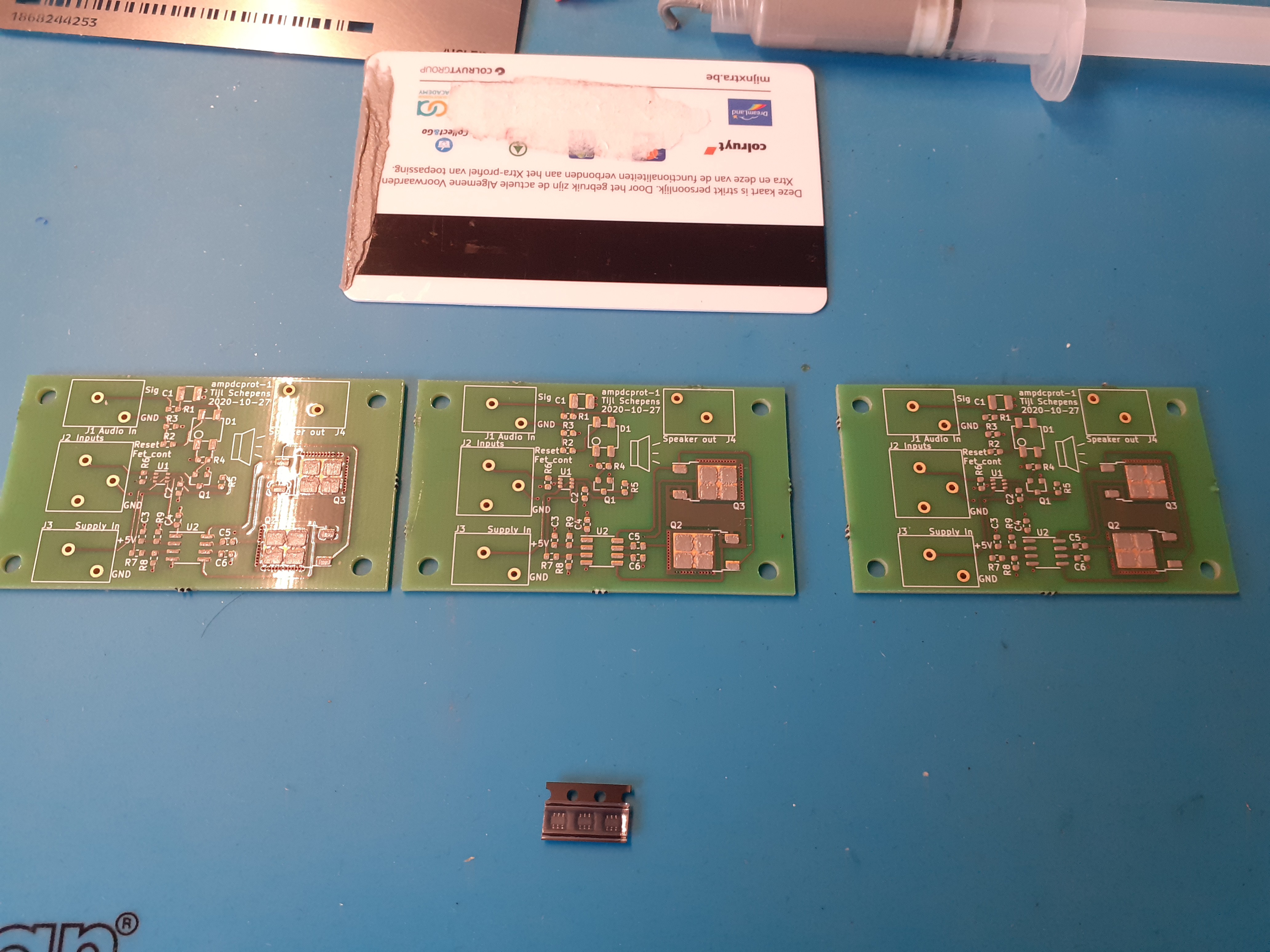
    For the connectors it seems that I made a mistake. I think I ordered the wrong ones as my footprint matches the datasheet.

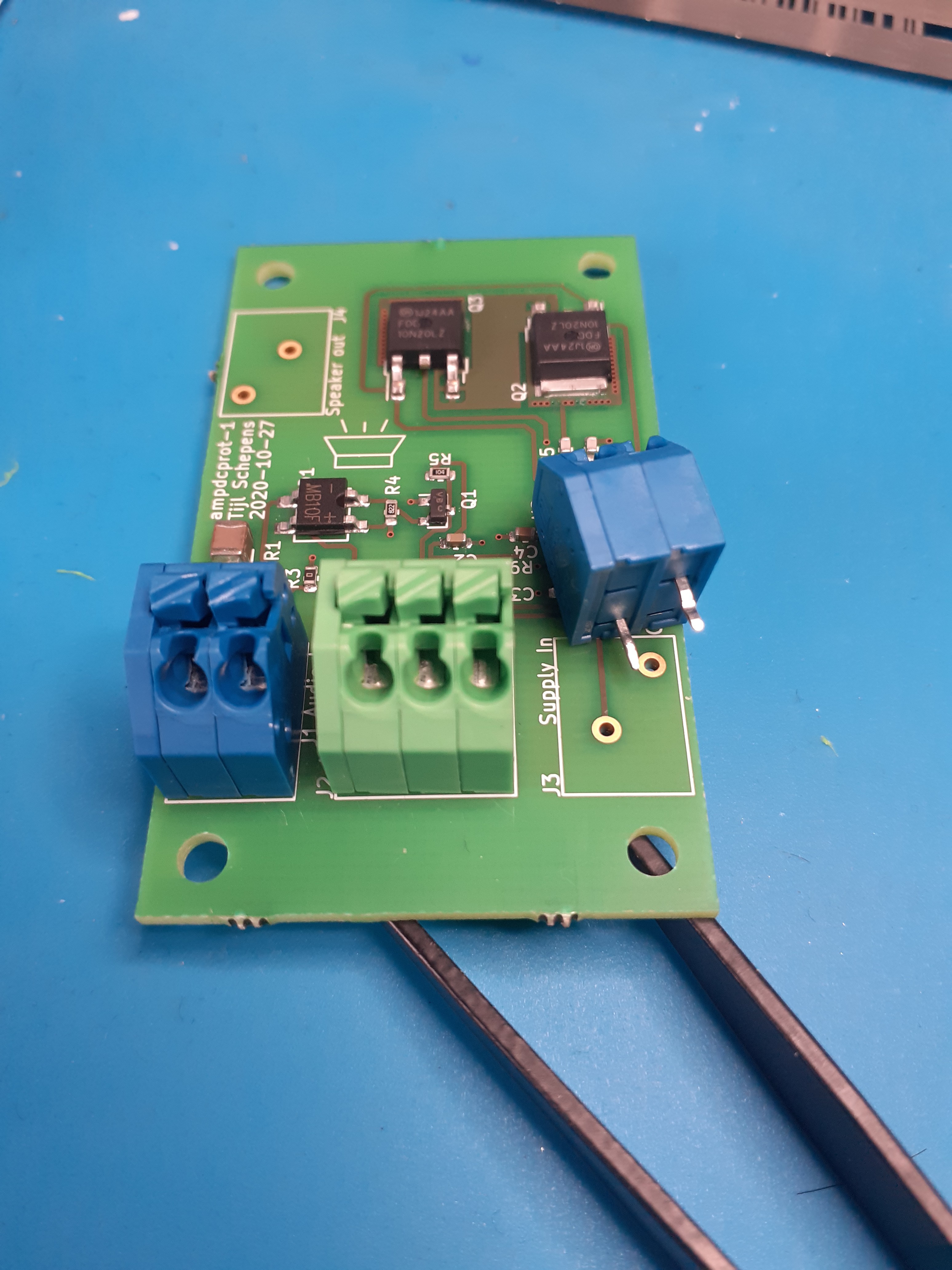
    The pins of the connector are swapped. So they do not fit...
    The good news is that these connectors are easy to disassemble. All the parts are just pushed together and can be separated with little force and a pocket knife.

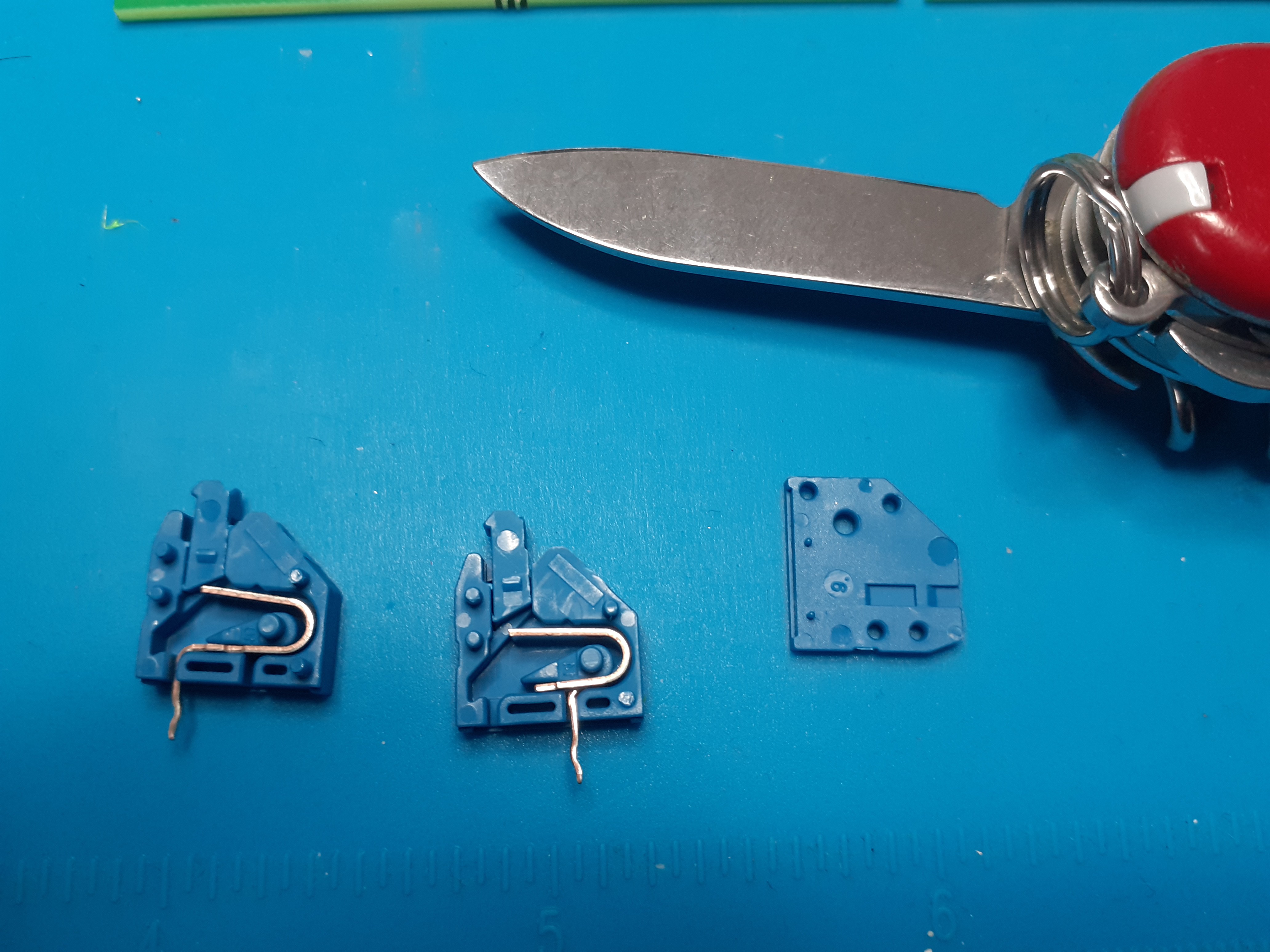
    Now that the three parts of the connector are loose, we can just swap the pins. That way they fit into our connector footprint!
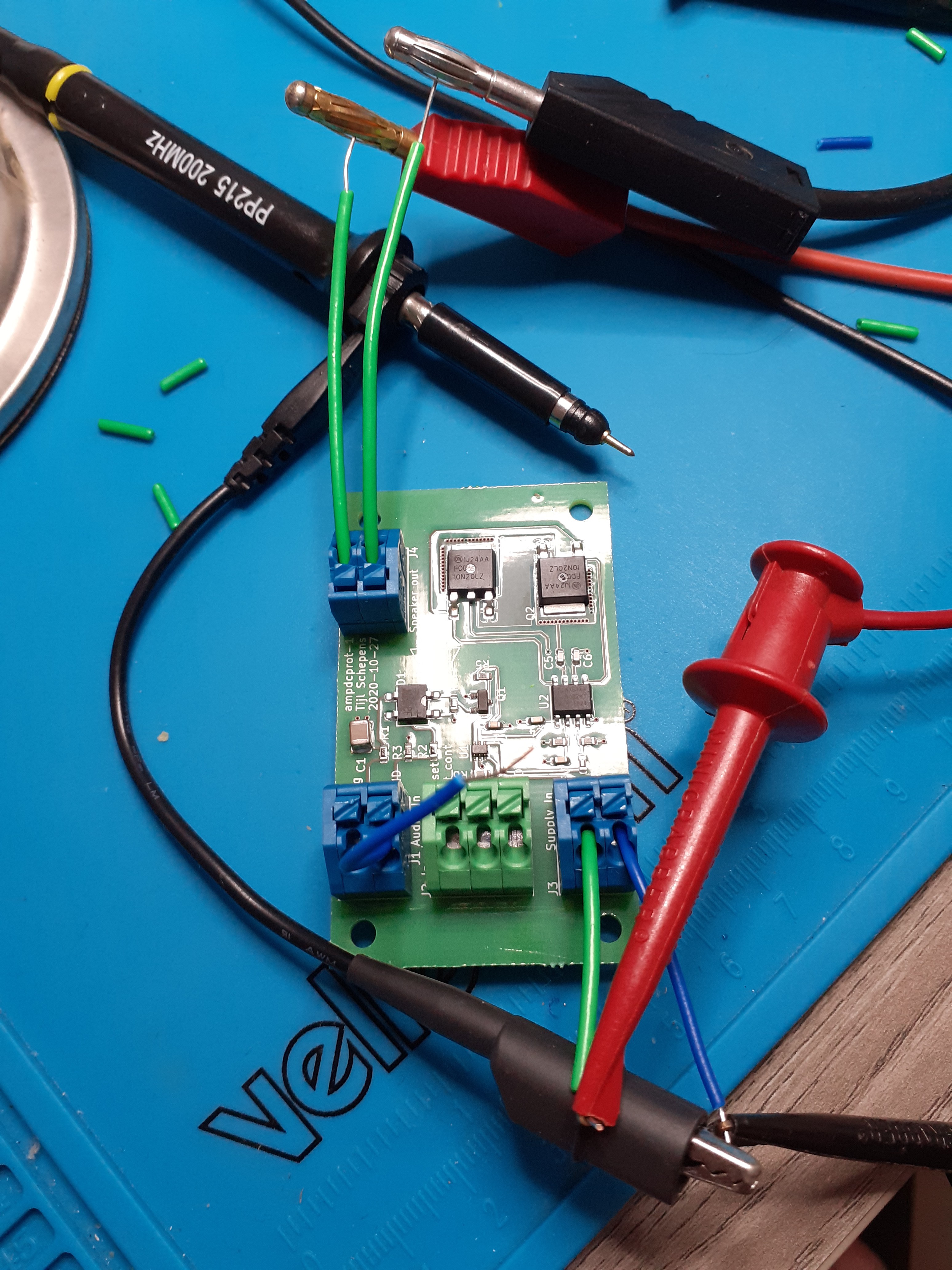
    The green connector does fit, so I must have ordered a wrong one for the two pins variant.

    Now that everything is soldered we can start doing some measurements on the board.


    I did some quick verification to see if I made stupid mistakes. On first sight it seems that the board works as expected. Now I can start to do some more in depth measurements!

View all 2 project logs

Enjoy this project?

Share

Discussions

Similar Projects

Does this project spark your interest?

Become a member to follow this project and never miss any updates