 Andrew Lamchenko
Greetings to all readers! In my article today I want to share with you my new device - temperature, humidity and pressure measuring device with a weather forecast function. The device works on nRF52 microcontrollers. This device uses a 2.9-inch e-ink display. The device is equipped with a BME280 sensor, there is also a place for installing sensors SI7021, HTU21D. Powered by CR2450 batteries. It can transmit data to the Smart Home systems, it can also work in the offline mode.
For this project, the GDEH029A1 e-ink display model was selected with a screen size of 2.9 inches. After about 3 months of testing, the manufacturers released a new model GDEM029T94 (V2 according to Waveshare) to replace this display.
The old model became difficult to buy, so I had to add support for the new display to the project.
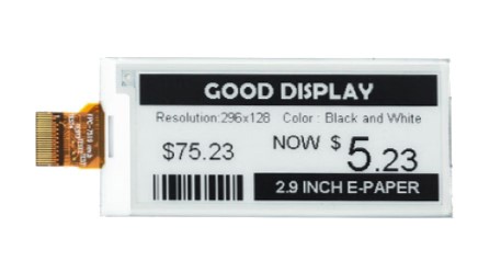
Display characteristics:
- Resolution: 296x128
- Operating temperature range: 0 - 50 C
- Consumption in operation: 3mA
- Deep sleep consumption: 1μA
- Minimum screen refresh time: 0.3 sec.
I developed several variants of boards at once for several variants of nRF52 radio modules from different manufacturers. I stopped at the MINEW MS50SFA2 (nRF52832) and EBYTE E73 2G4M08S1C (nRF52840), E73 2G4M08S1E (nRF52833) modules.
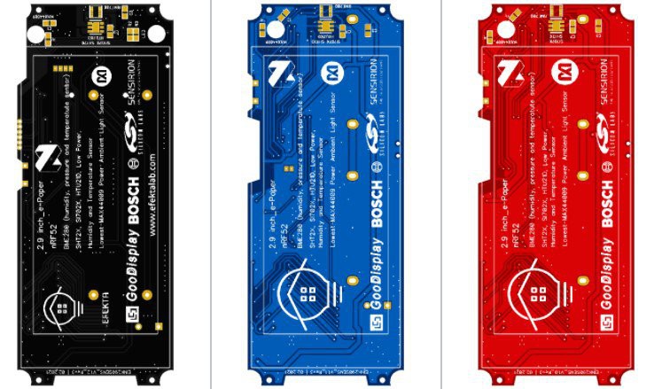
The MINEW MS50SFA2 module has a small size, but not a very large number of legs brought out. All available MS50SFA2 legs were used in my project. The E73 modules have many more legs, so an extended version of the sensor was subsequently developed. In the extended version adds an active buzzer, a MAX44009 light sensor, and replaces the CR2450 with AAA batteries.
Device circuit:

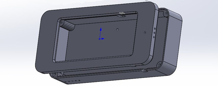
The case of the device is printed on an FDM 3D printer, to achieve a more or less decent look, the body must be sanded with sandpaper and polished after printing. Since the sensor has an LED, and in the extended version there is a light sensor, it was necessary to make two through holes in the case, after drilling the holes, they were filled with polymer resin for an SLA 3D printer and an ultraviolet lamp was illuminated. After that, the case of the device was polished.
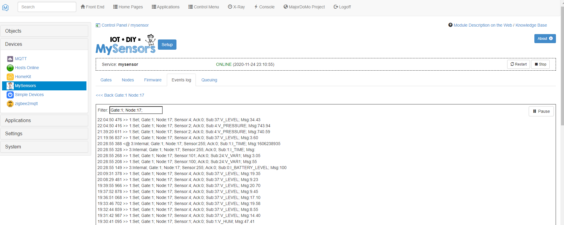
The device software was made to work on the MySENSORS network (www.mysensors.org), an open source home automation project. By the way, the sensor will work normally without a network. At the moment, the my project supports work with two display models GDEH029A1, GDEM029T94. Perhaps later, support for tri-color displays will be added.
I will describe a little the functionality of the device. When the device is turned on, it tries to find a network, if the network is not found, then the device goes into the main operating mode without working in the network (does not send data), but periodically makes short requests to search for the network (~ once an hour). The sensor polling interval is 1 time per minute, the screen is refreshed and data is sent (if the network is available) when the temperature data changes by 0.5 ° C, humidity by 1%, pressure by 1 unit, illumination level by 1 lux, according to the change in the weather forecast ... The battery polling interval is set by the user in the range from 1 hour to 24 hours; by default, the polling is performed once every 6 hours.
The device can be configured using external commands from the Smart Home interface. To do this, activate the desired menu item "Sensor configuration" by pressing the "Menu" button. After activating the configuration mode, the sensor will switch to listening mode for 20 seconds. You must send a command in this interval. External commands can be used to adjust the battery check interval, change the display of information in inversion, turn off the LED, turn off the beep.
Description of the algorithm for calculating the weather forecast - (NXP Application Note 3914 | John B. Young)
When working in a radio network, the sensor transmits data:
- Temperature,
- Humidity,
- Atmospheric pressure,
- Illumination level,
- Weather forecast,
- Signal level,
- Battery charge level,
- Reason for reboot

To compile the required software version, you need to configure the MyConfig.h file.
The file specifies:
- Information output language (RU, ENG)
- Power optimization mode for data transmission
- Light sensor connection
- Active buzzer connection
- Data transfer rate
- Version of the connected display
//#define EINK_V1
#define DCPOWER
#define LIGHTSENS
#define BIZZER
#define LANG_EN
//#define MY_DEBUG
//#define MY_PASSIVE_NODE
//#define MY_NODE_ID 101
#define MY_RADIO_NRF5_ESB
#define MY_NRF5_ESB_MODE (NRF5_1MBPS)
//#define MY_NRF5_ESB_MODE (NRF5_250KBPS)
#define MY_RESET_REASON_TEXT
#define SN "EFEKTA WeatherStation 290"
#define SV "0.45"
The consumption of the device in sleep mode is on average 3 μA (more by nRF52840), in sensor readout and screen refresh mode 5mA (average), in data transfer mode 8mA (average), the transmission time of one message is 10ms (ideal conditions).
The device design with the MINEW MS50SFA2 module can be easily duplicated. Of the difficult moments, one can single out the soldering of the connector for the screen cable. How to make it easier I recommend watching my short video on soldering the connector. The sensor can also be purchased ready-made, thereby supporting my open-source developments.
Connector soldering video:
Video demonstrating device operation:
The readme file (on my GitHub) contains instructions for installing and configuring the environment for editing and compiling device software.