 pRoFiT
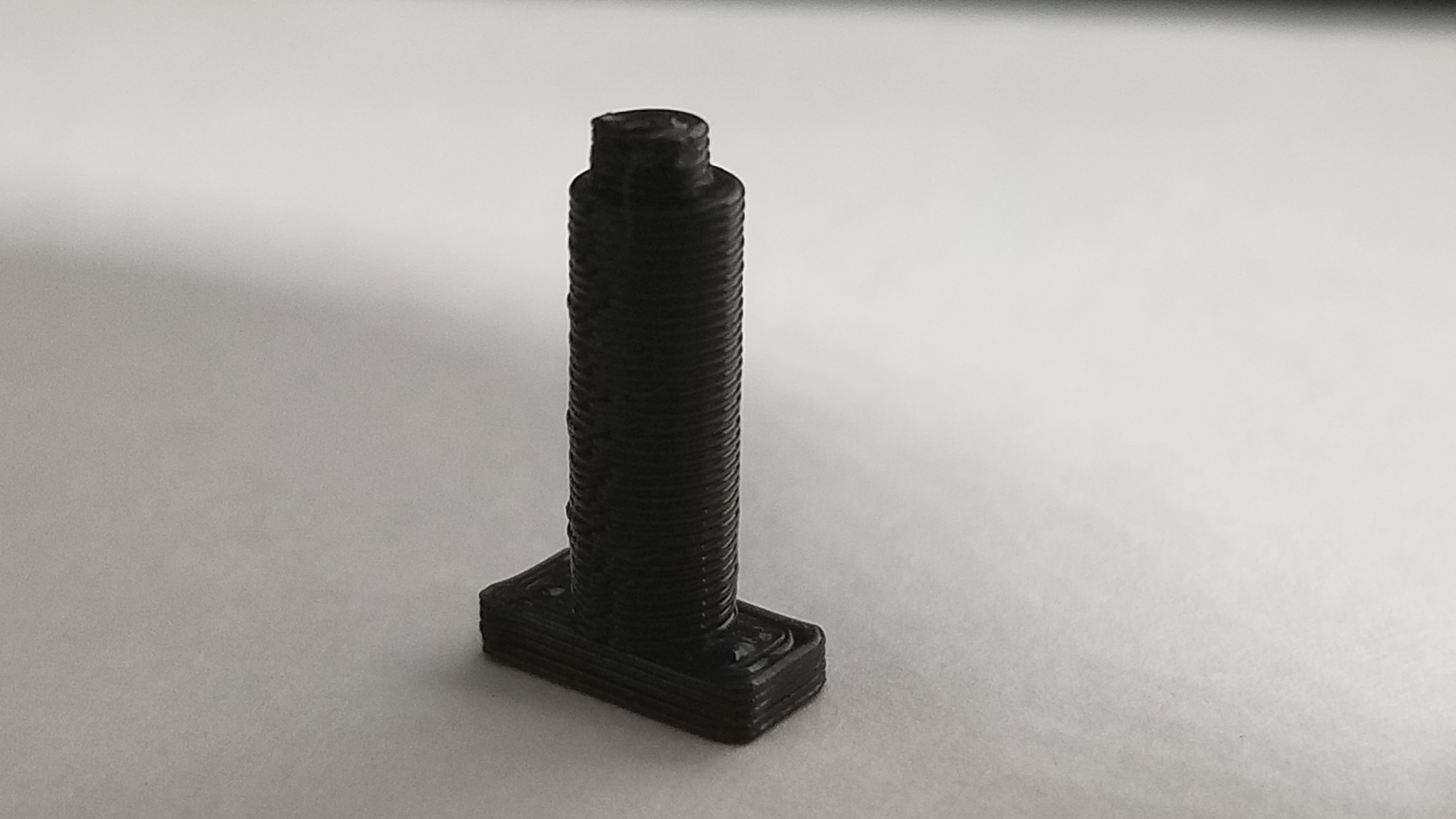
Purchased a cheap set of mechanum wheels and continuous servos. 3D printed servo holders to lock into a 4x6 proto board set for the chassis. 3D printed a case for the maxiduino.
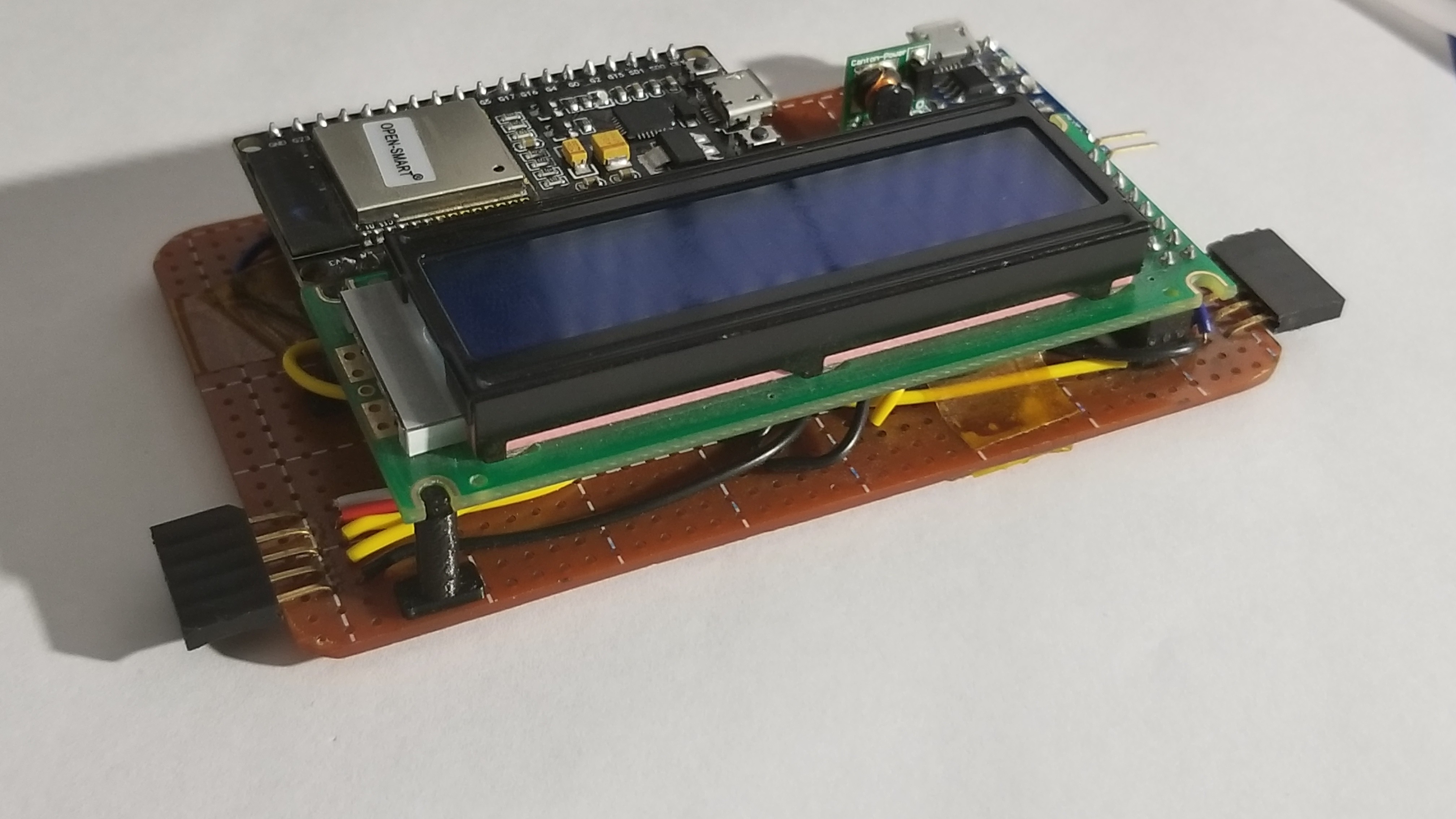
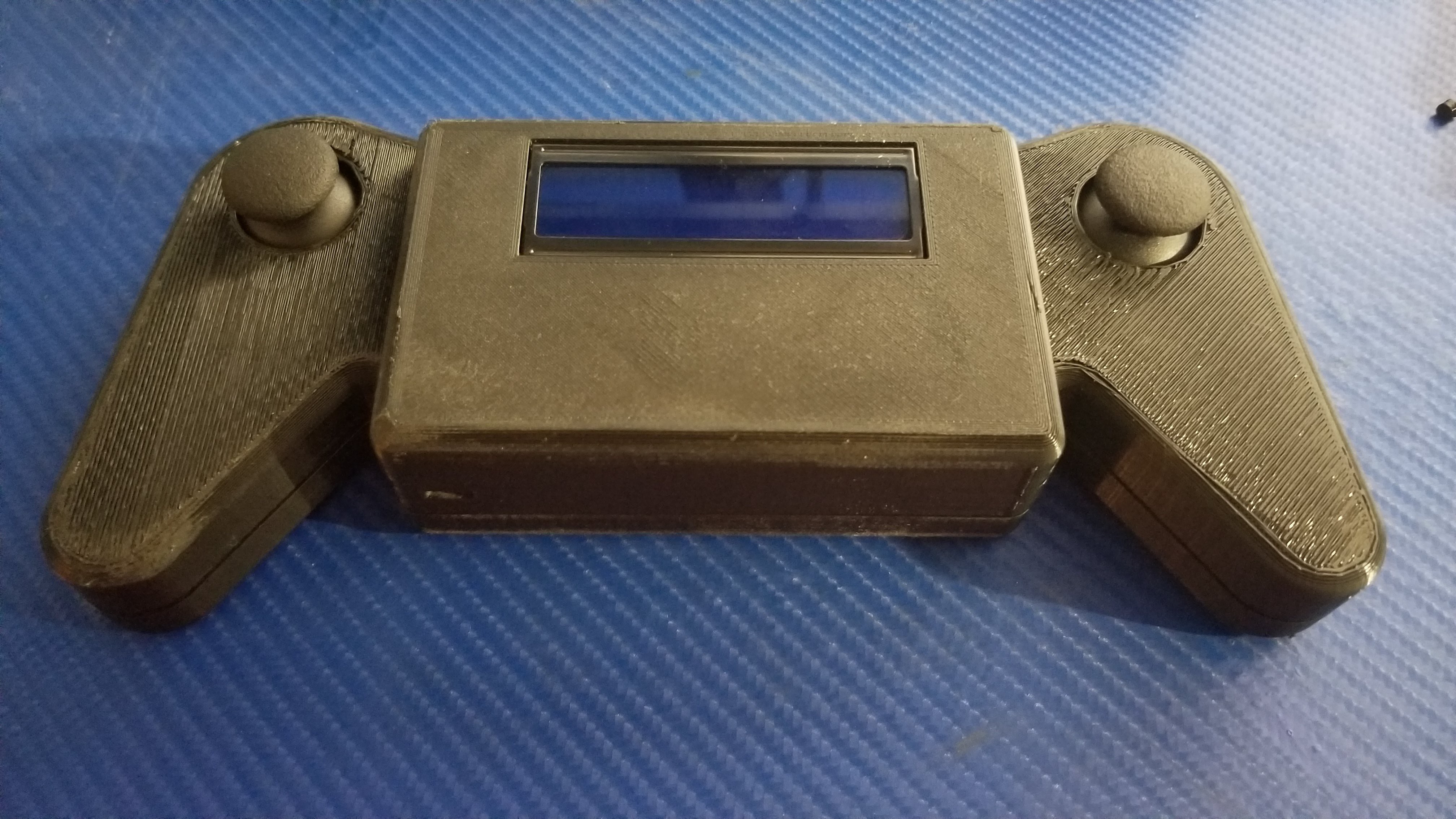
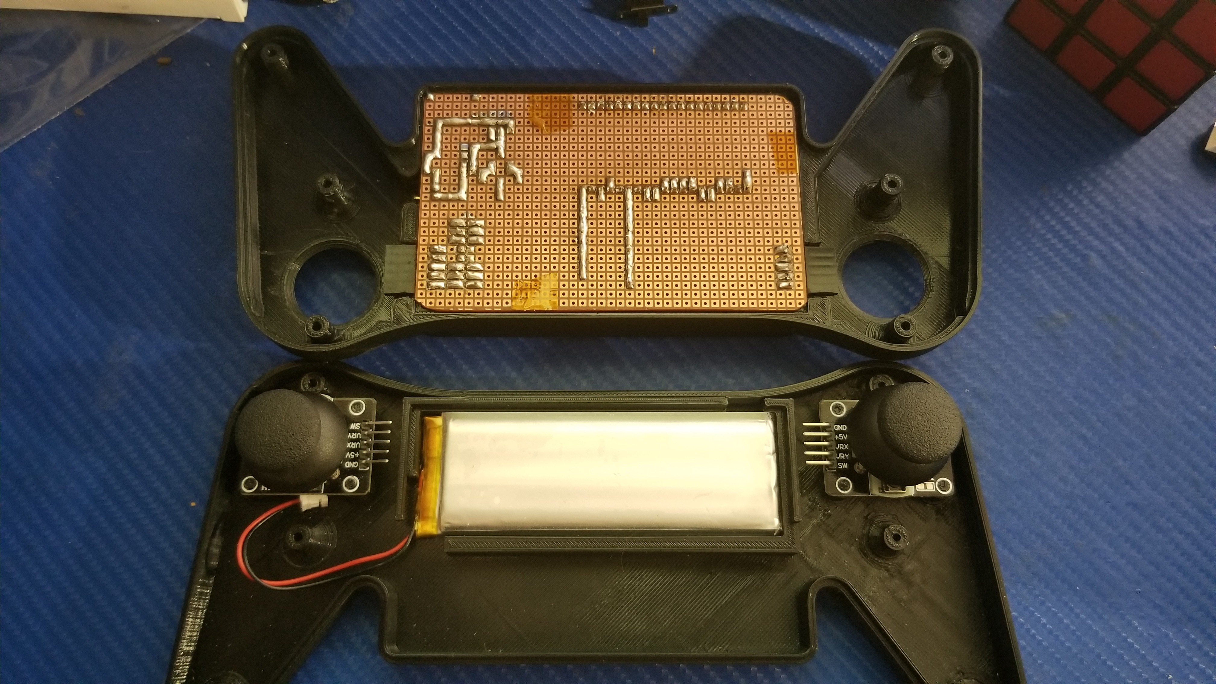
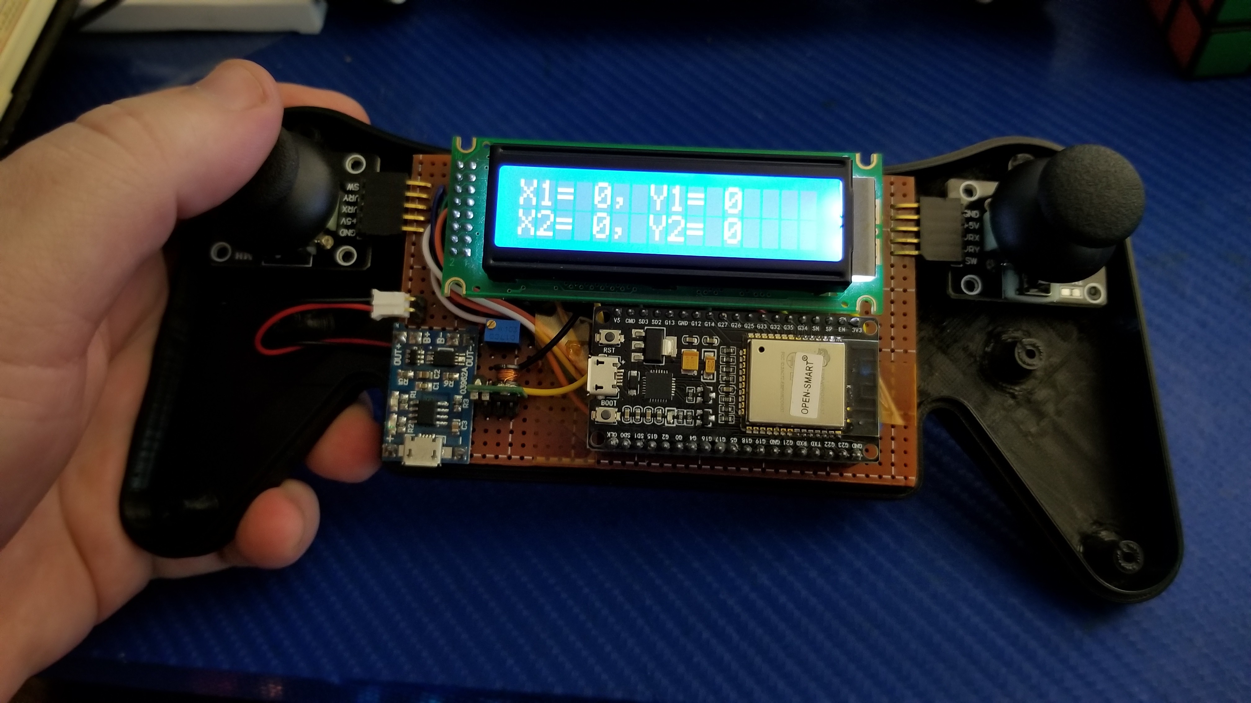
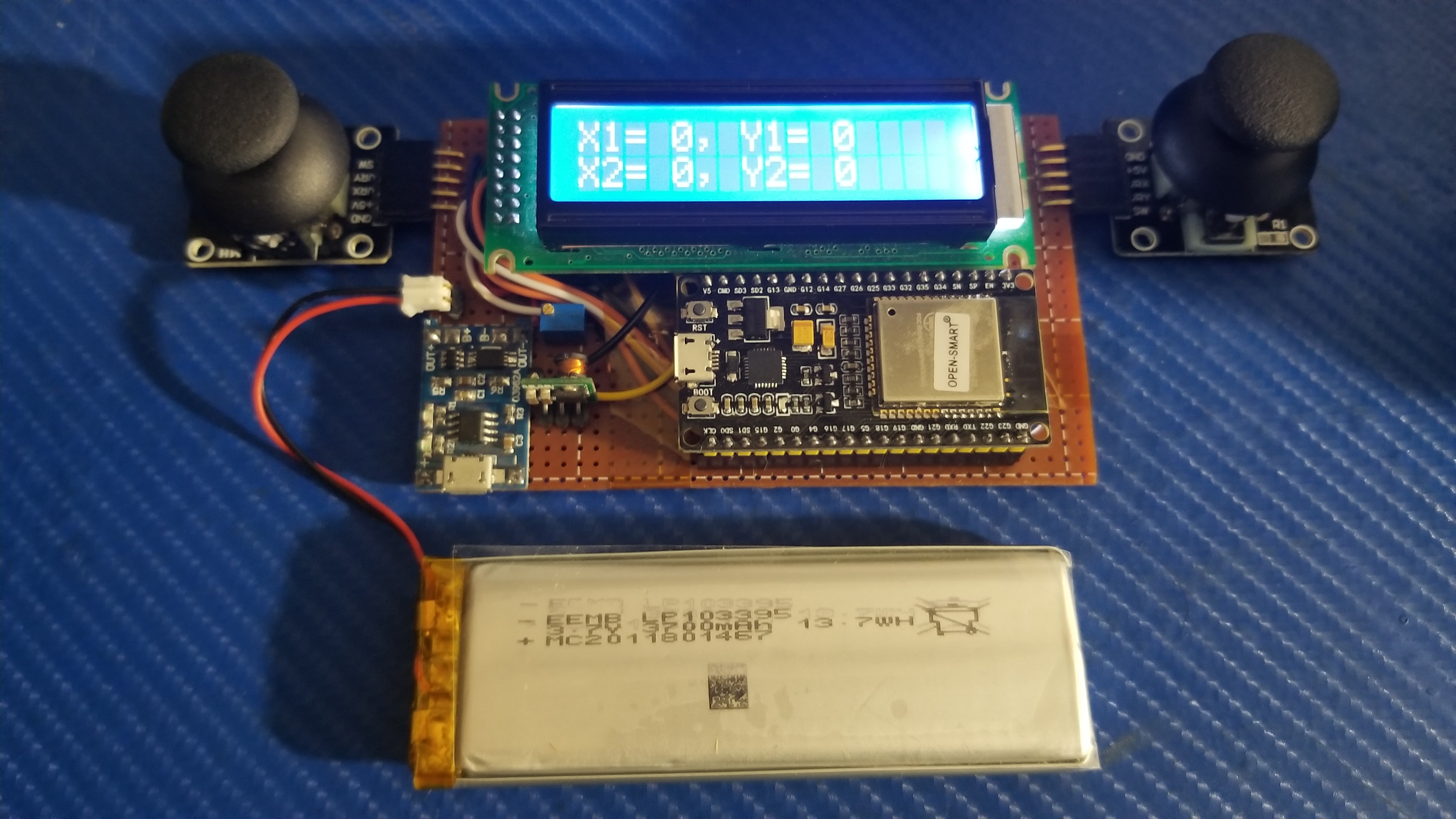
Basic controller is wired and seems to be functional. Need to work on combining joystick lcd into one project. Then add wifi output to send to robot.
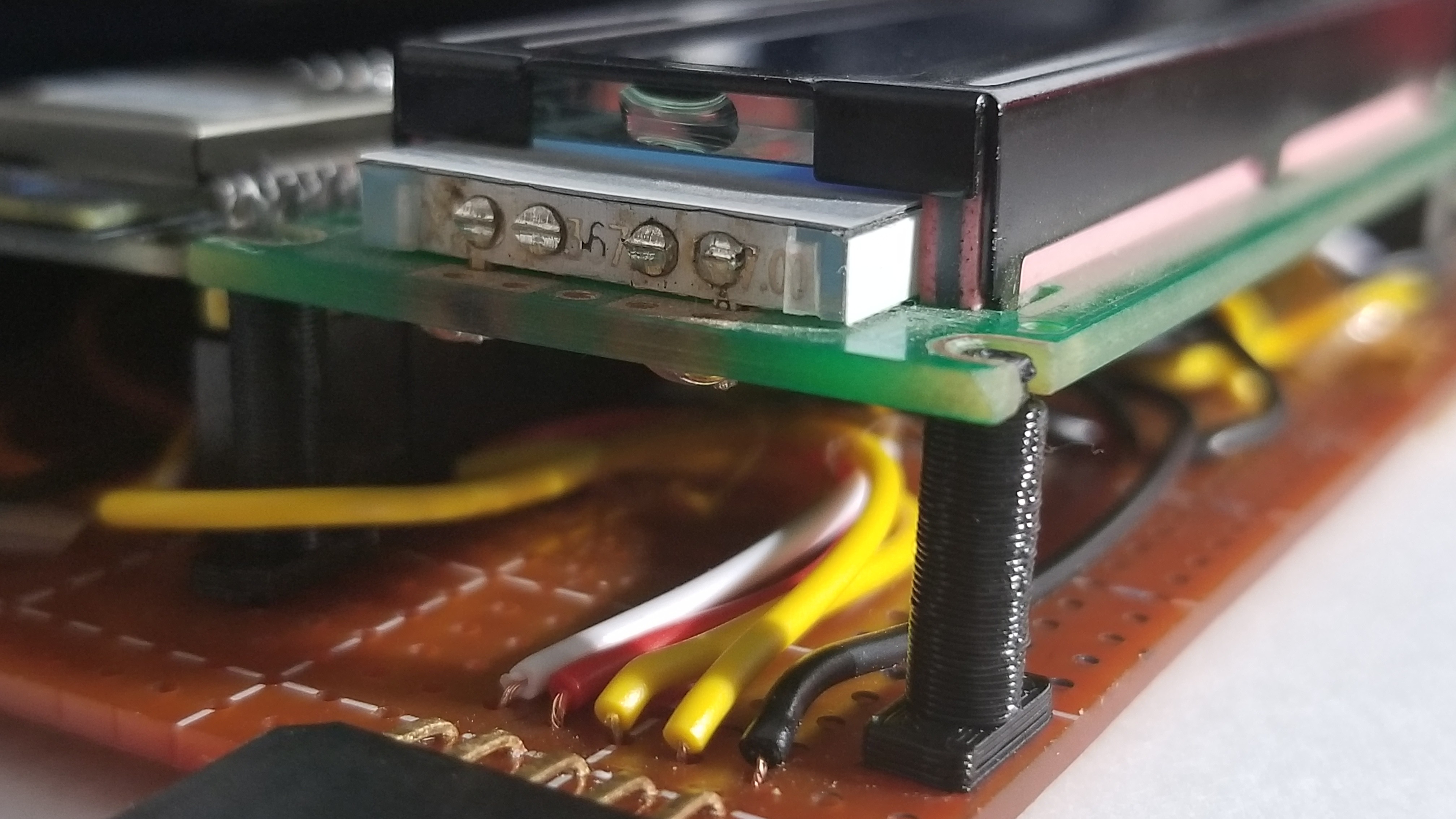
Maixduino has ESP32 for wifi and that is simple enough to get working in MaixPy IDE. And i2c 16 channel controller from adafruit is controlling the servos. So i have plenty of servos i can add.
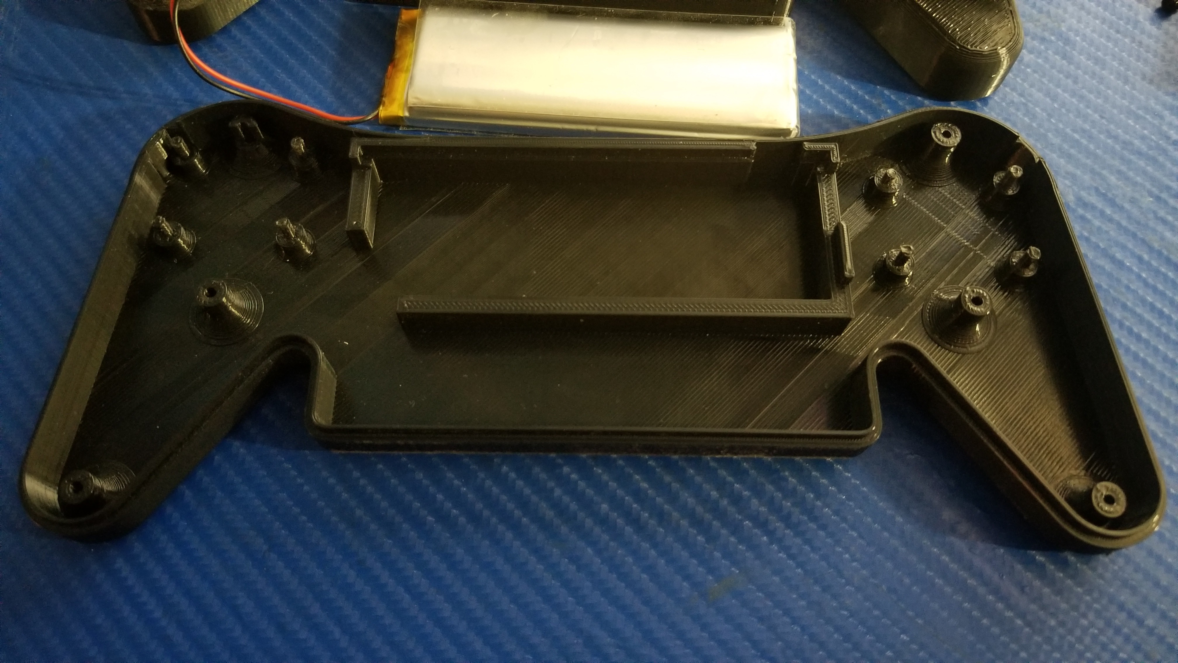
Power is 10,000mAH usb battery fits in the chassis. Should run ~24 hours on a charge. Need to check power consumption to be sure.
3500mAH lipo on its way for the controller. Have a bat to 5VDC converter will use for controller power. I think ESP32 5V pin is not the best way to power so i will run 5V through usb connector.. I've tried powering ESP's before from VIN and had issues with RS232 from USB causing it to not boot. So this time i will power through usb connector.
Coding will be mix of Arduino for controller and Python for robot. The Arduino Maixduino was giving me issues and i can get the lcd and camera up no issue on the MaixPy IDE python editor. Will need to learn micro python but it's close to aruduino and C that i think i will be fine. Plenty of online tutorials i can look at.,
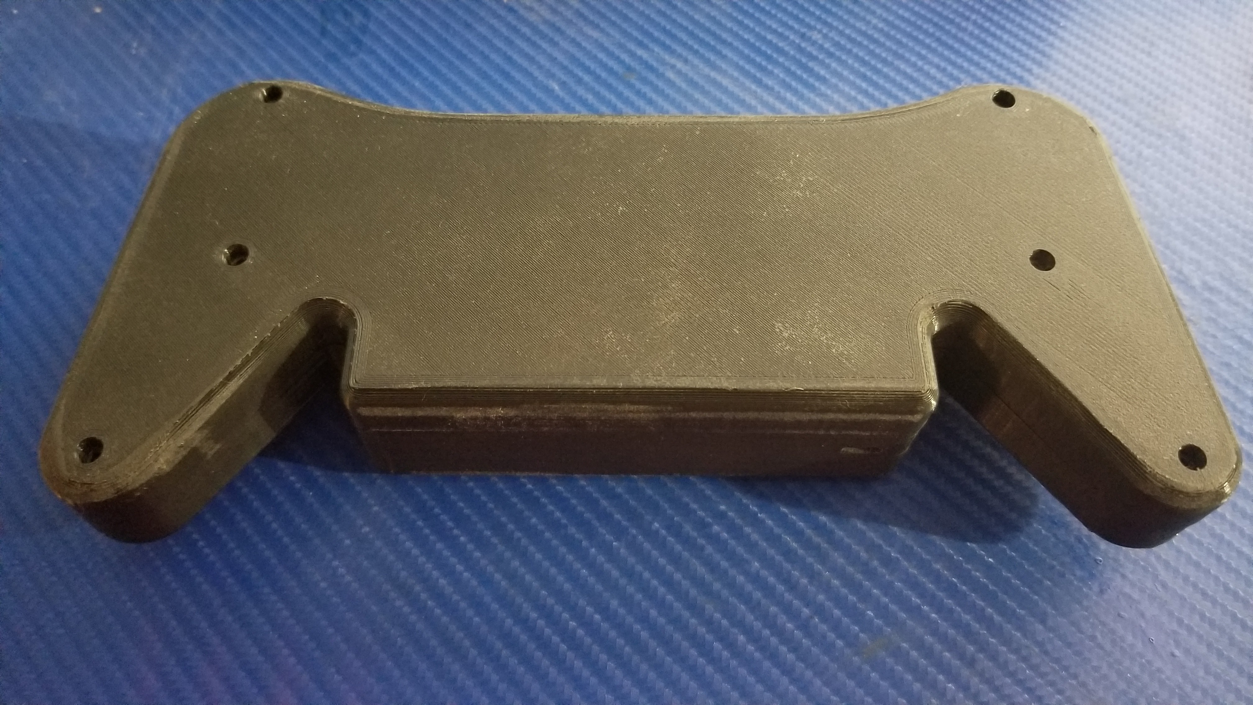
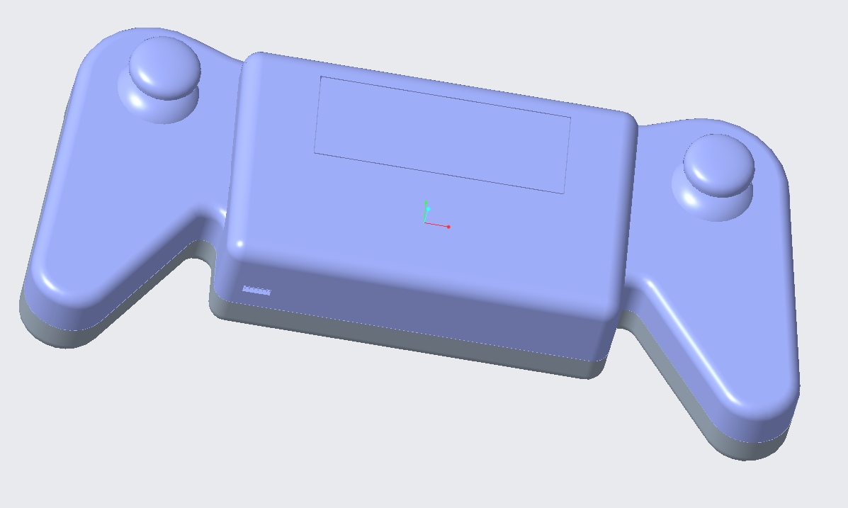
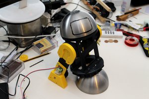
 As you can see the top piece looks great. I hit it with sandpaper to take off some rough edges. I may do some more after i get it all fitting right.
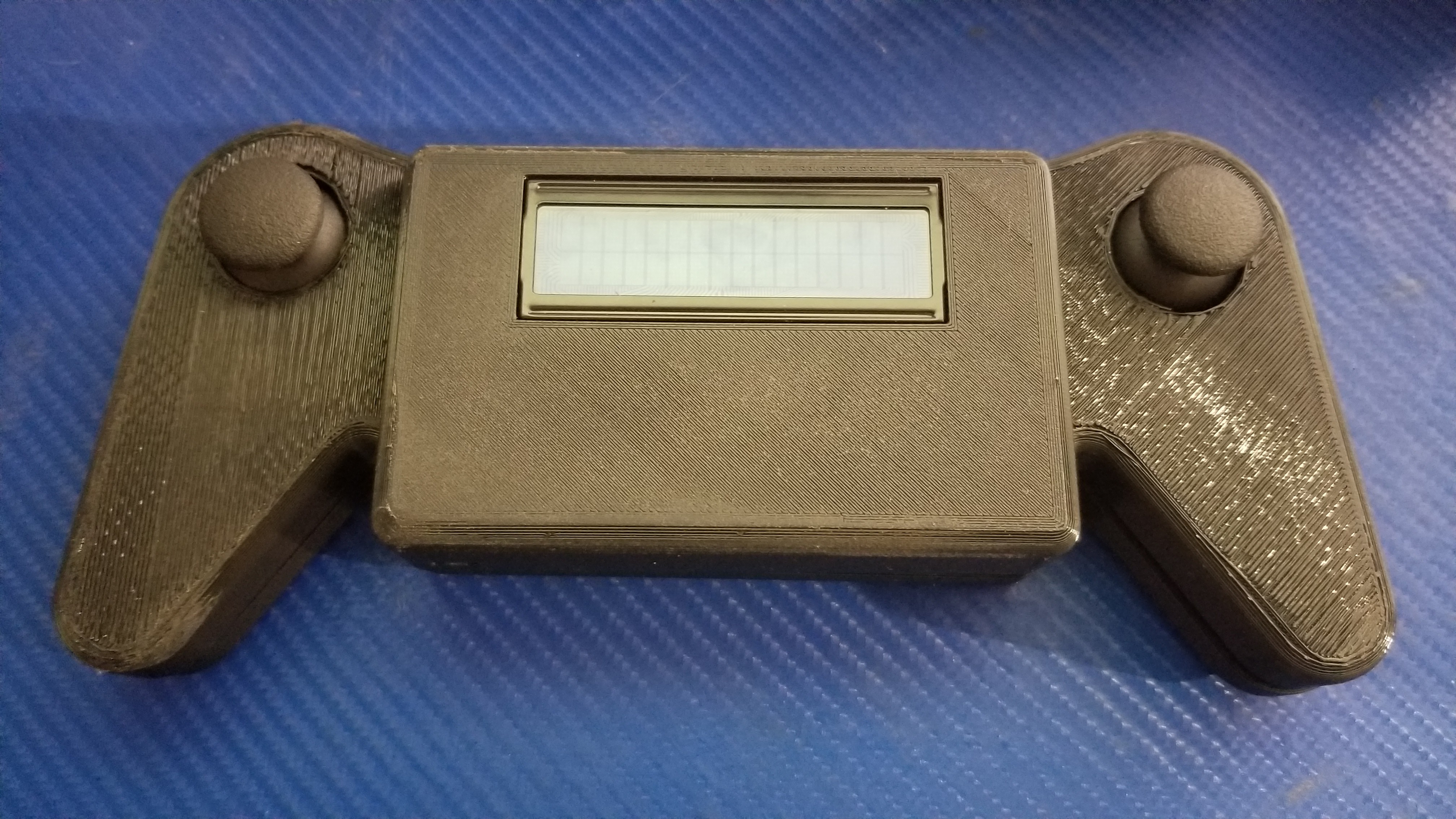
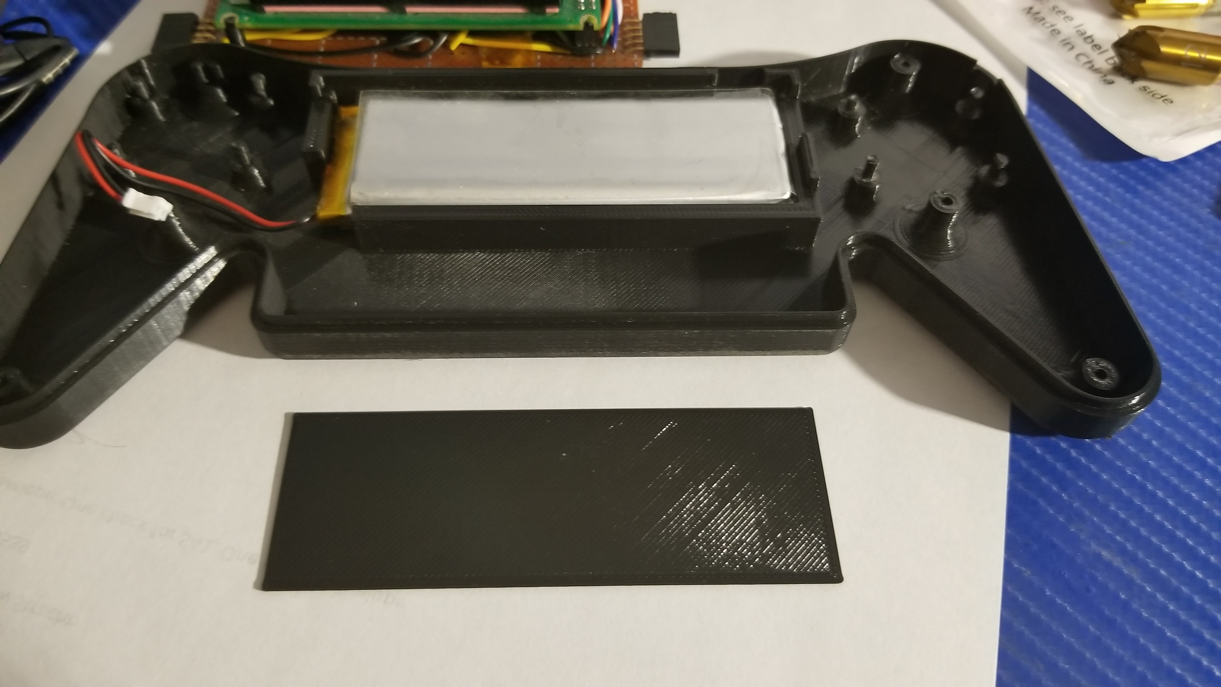
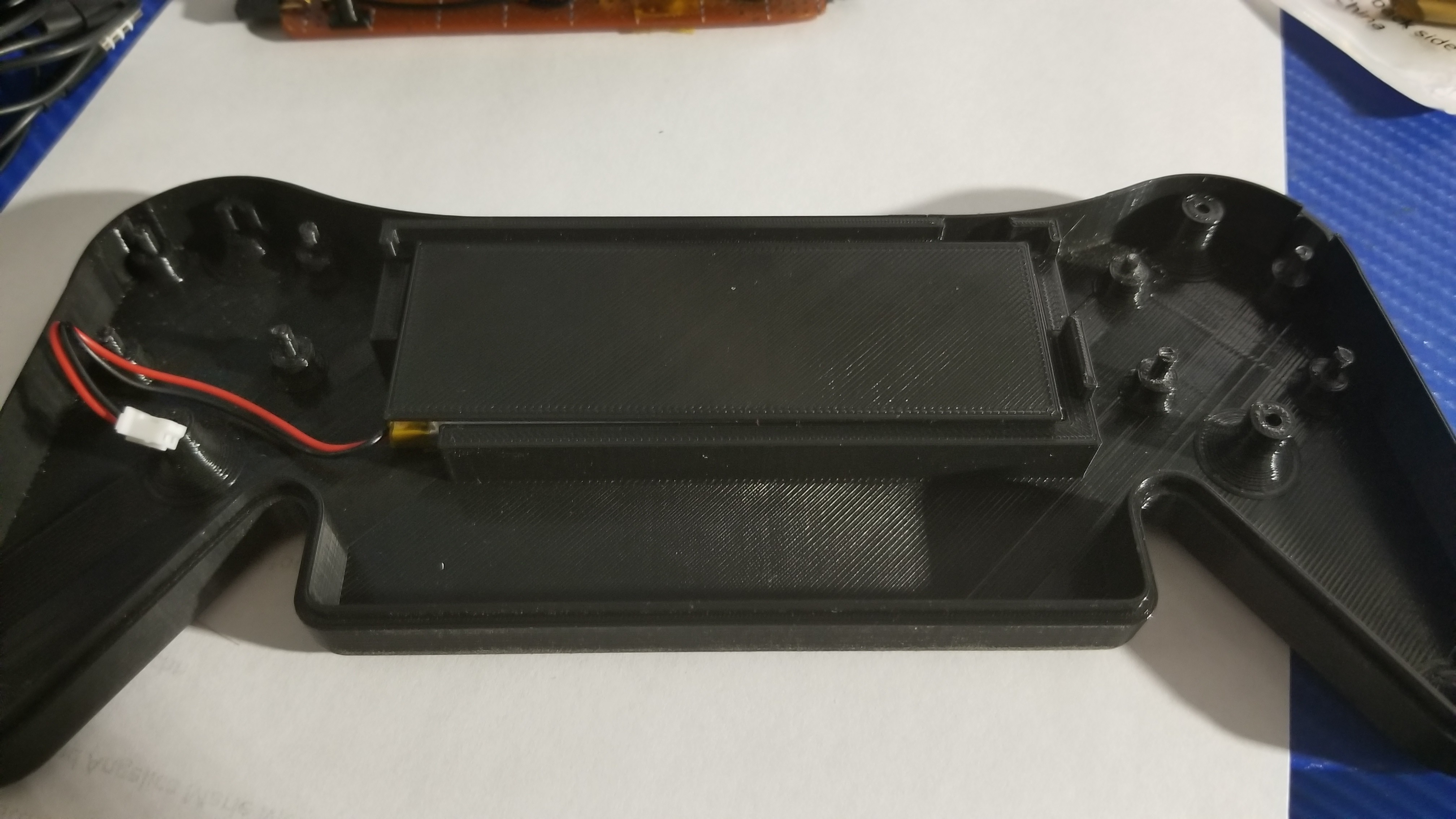
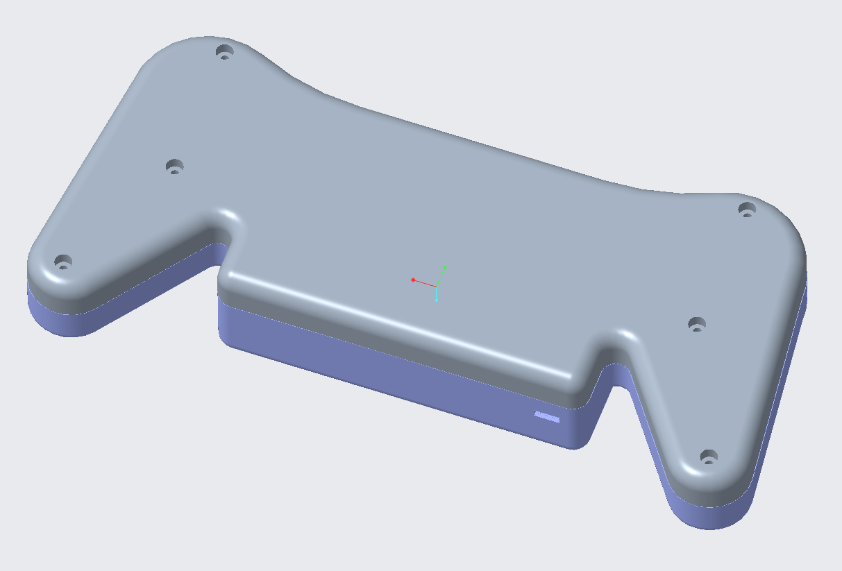
 You can see the right side is coming up from the bed. and the top right too. caused that area to not look clean. but its on the inside so? oh well.
 Battery fit perfectly in there.
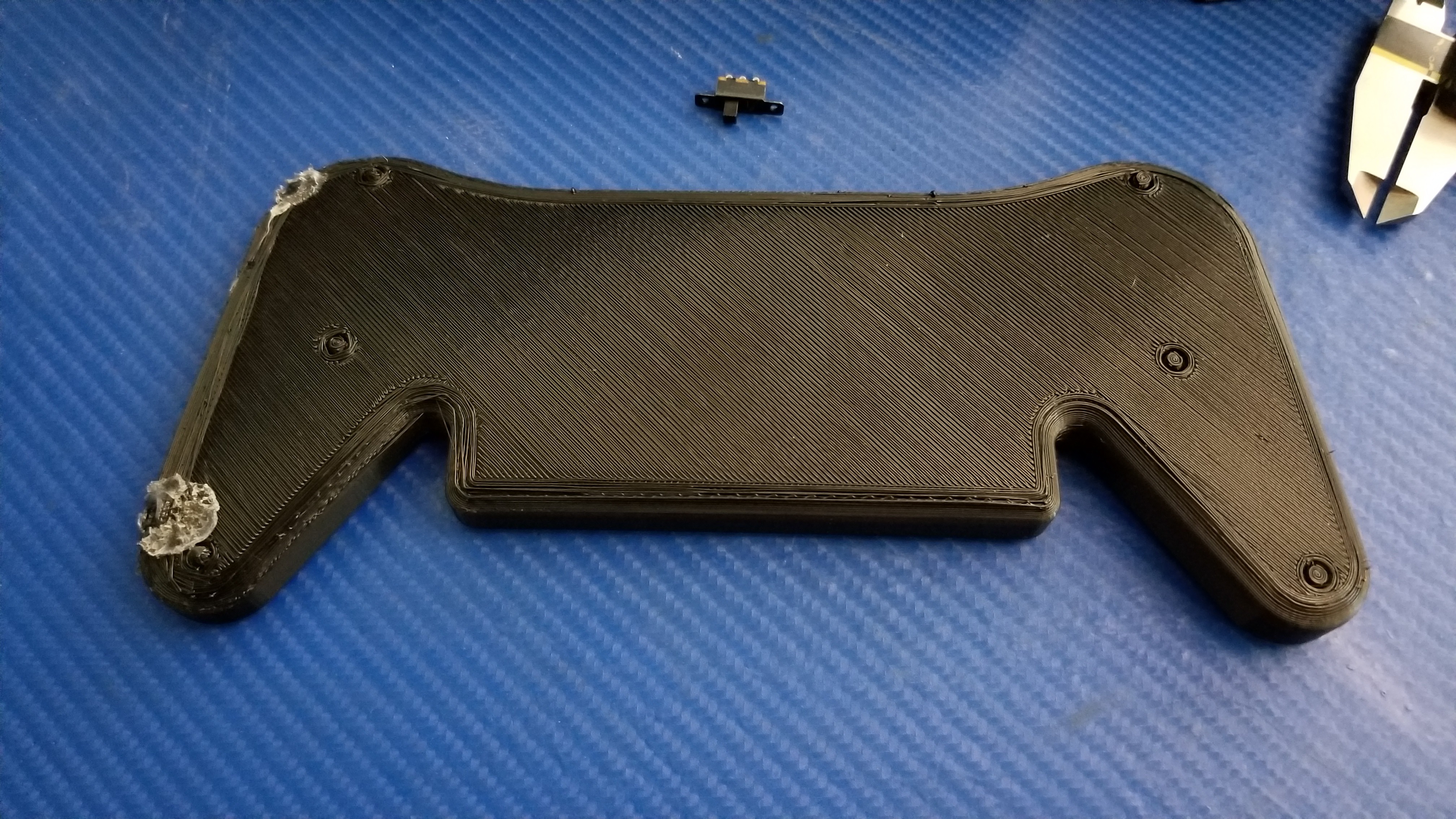
 Cedric Anné
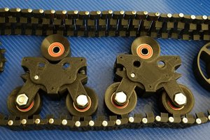
 davedarko
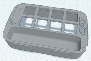
 mrpendent