 Jung Hoon Lee
- Introduction
This project was to make a tiny freezer that is yet big enough to be functional. Here I would like to share my experiences in making miniature-sized (93x96x116mm) functional refrigerator, specifically optimizing variables like, different TEC size, stacking, voltage and current adjustments, minimizing heat dissipation and maximizing cooling performance simultaneously.
There are lots of methods of cooling and variety of cooling systems known and be chosen from. In order to satisfy condition that it would be compacted in a very small space (and cost effectiveness was also a factor), I decided to use thermoelectric module cooler (TEC) for my cooling apparatus. TECs are simply solid state heat pumps. They move heat from one side to the other, causing one side hot whereas the other side cold. TECs do not have a fix or rated temperature when applied power, which means that TEC modules could be stacked to achieve lower temperatures.
- Initial Tests
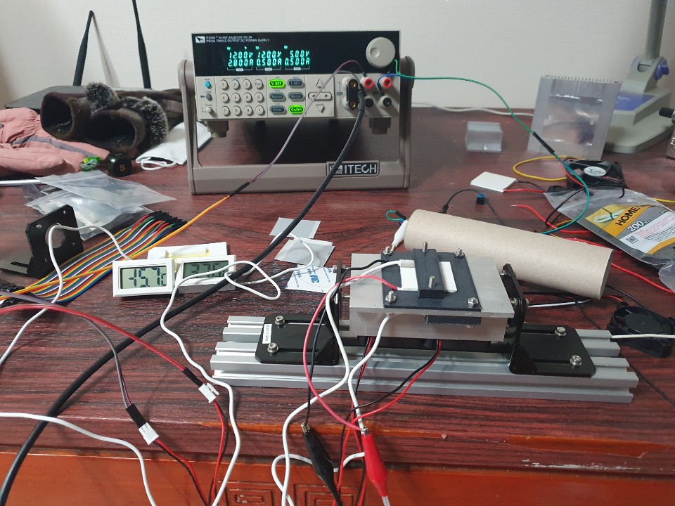
The desirable cooling system should be as small as possible. For this reason, I started with the smallest heat sink yet big enough to remove heat effectively from a TEC surface, and gradually increased in size. The thermal conductivity of the thermal paste I used for the primary tests were 1.42W/m-k and for the 4th 9.2W/m-k. All the test were done in a room of 23~25 degrees C.
1. The first test was performed with 45x60x24mm heat sink, 3030 12V 4A TEC, and 40x10 fan. I was able to achieve the maximum of -7 degrees C at 12V 2.5A. However, when more than 2.5A was applied, the cooling was rising in temperature, which was probably caused by the capacity limit of the small heat sink. To overcome the capacity limit, a cube enclosure (60x50x50mm) with 6mm thick foam was added to contain the cool air inside of the cube. But that failed to reach my targeted temperature which is below freezing.
1-1 3030 TEC test
1-2 with chamber
2. Second test was performed with 90x60x24mm heat sink and two 40x10 fan, which is double the size in length of the 45x60x25, and 3030 TEC 12V 2.6A. With this setting I could get almost double the temperature, that is -13C, but still that was not enough to produce cooling. I realized that signal or mono layer of TEC was not able to cool the cube enclosure below freezing temperature enough to freeze water or ice cream stored inside because of the limited sized itself.
2-1 3030 TEC test
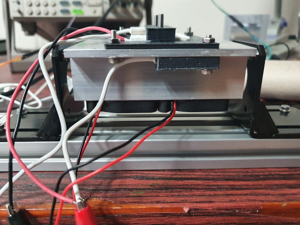
2-2 With chamber
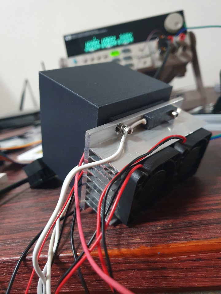
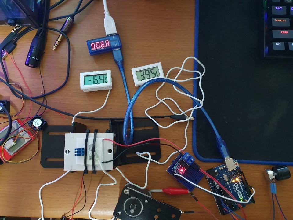
3. Third test was performed with two layered TECs, which was 100x95x24 heat sink, 4040 TEC 12V 4A for the bottom layer and 3030 TEC 12V 4A on the top of the bottom layer, 92x38 fan was used.
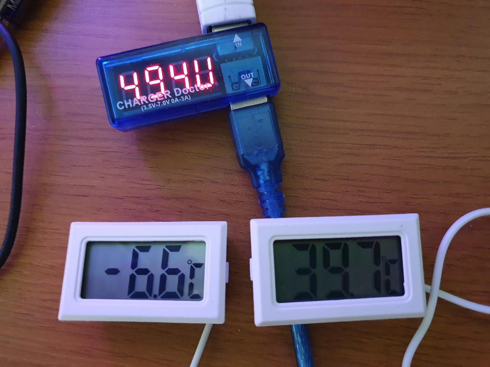
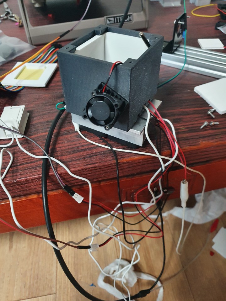
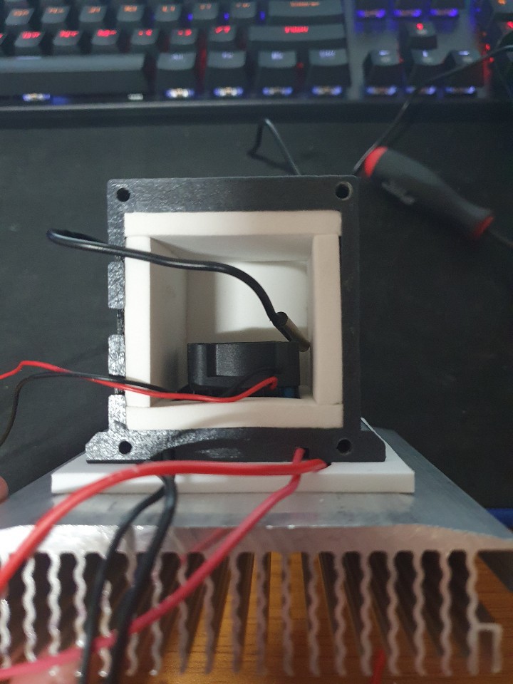
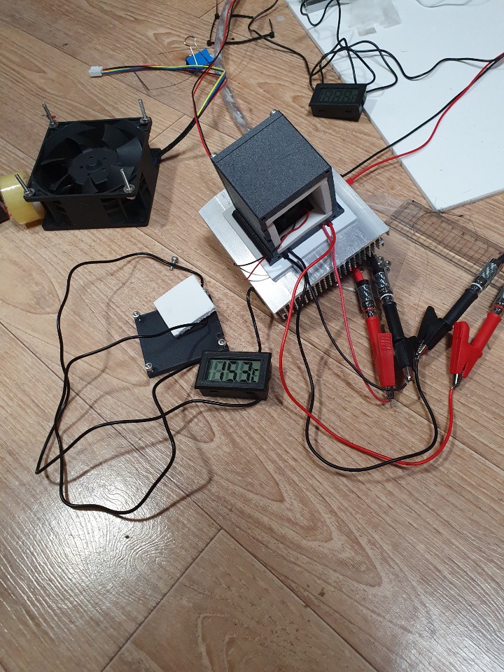
With the setting of 4040 TEC 12V 2.6A and 3030 TEC 5V 1A, I was able to get -23C, roughly 36W for both TECs and a value of -23C. I designed a small enclosure (60x50x50mm) to measure the chamber temperature. With the same test setup mentioned above, I added a 30x30x10 heat sink to the cold side of the 3030 TEC. Despite the surface temperature of -23C, the lowest chamber temp I was able to achieve was 4 degrees lower than ambient temperature. Soon I realized it was due to the lack of circulating fan inside the chamber for churning the cooled air. After adding a 25x25x10 fan on top of the cold side heat sink, I was able to get a lowest temperature of -5C, which was much lower than my expectation. However, other problem came up with the size of the heat sink. The heat sink of 100x95x24 that I used was too big to be fitted into the miniature-sized frame of the fridge. Therefore, I had to optimize the size of a heat sink for it to satisfy the cooling capacity by trial and error method.
3-1 4040, 3030 TEC test
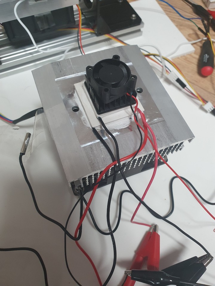
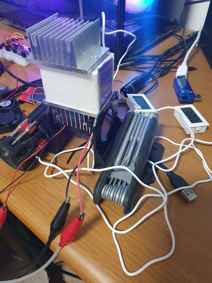
 4. I got three different heat sinks 92x92x30, 77x77x30, and 85x85x44. After some tests, 77x77x30 heat sink was proved to be the exact form factor for my design, namely 77x77x30 heat sink with 80x10 fan. I did a test with the same setup as the 3rd test (4040 TEC on bottom,...
 Andrey Bykanov
 Michael
 Simon
Simon
 RoGeorge
could you release the 3d models and code and BOM?