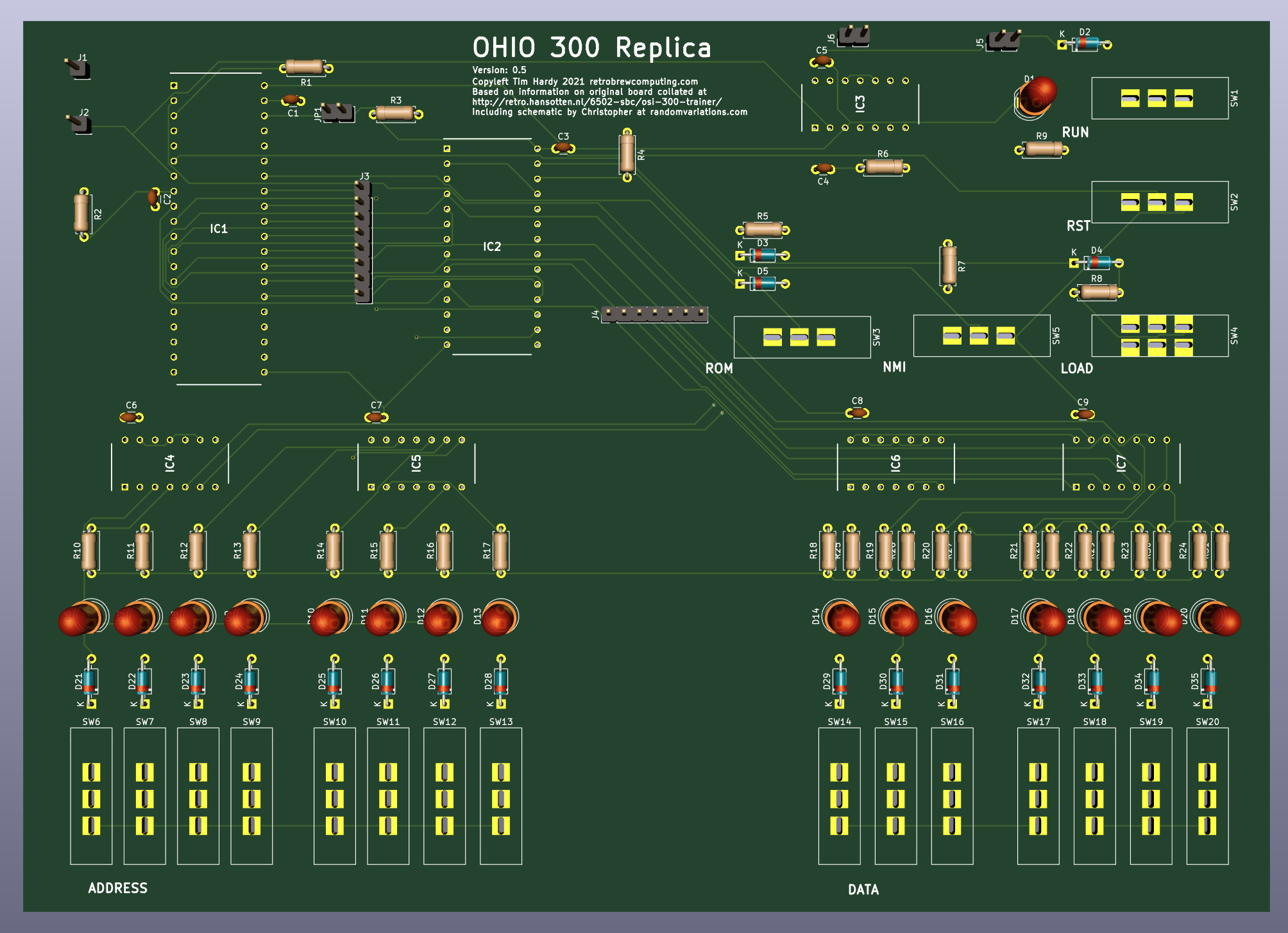
Close
0%
0%

OSI 300 Replica

A replica of the OSI 300 from Ohio Scientific: a 6502 trainer from 1977 with 128 bytes of RAM and binary switch programming

timTim
Similar projects worth following
I have always been fascinated by computers with front panels and long wanted to build my own. When I read a Hackaday article last year on the OSI 300 I knew this was the starter project I needed to inspire me to get over the steep part of the learning curve.

Design Goals

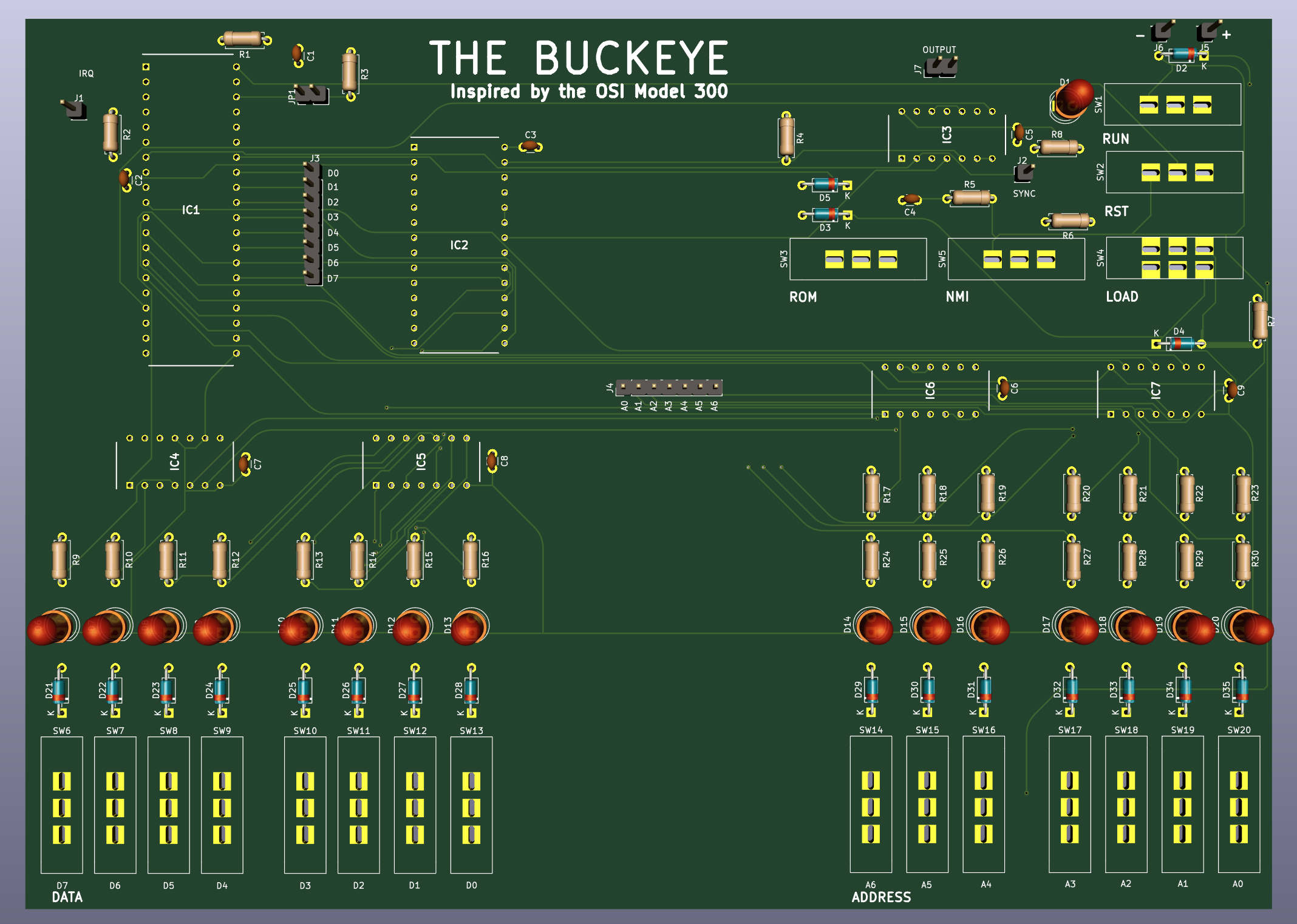
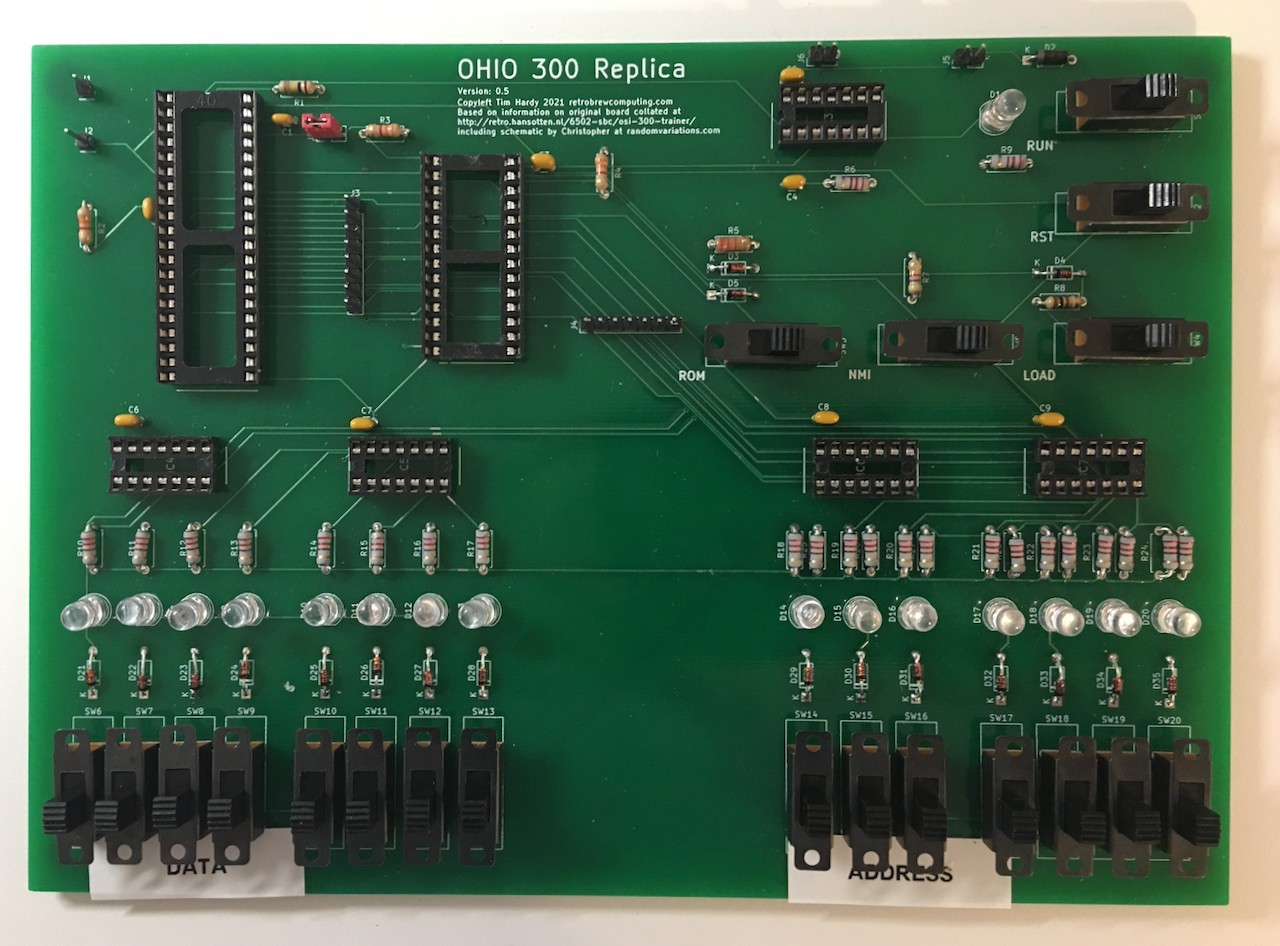
  • Restrict address space to 128 bytes of RAM by having only seven switches like the original even though unlikely to find physical RAM smaller than 64K
  • Use modern, easy to source components
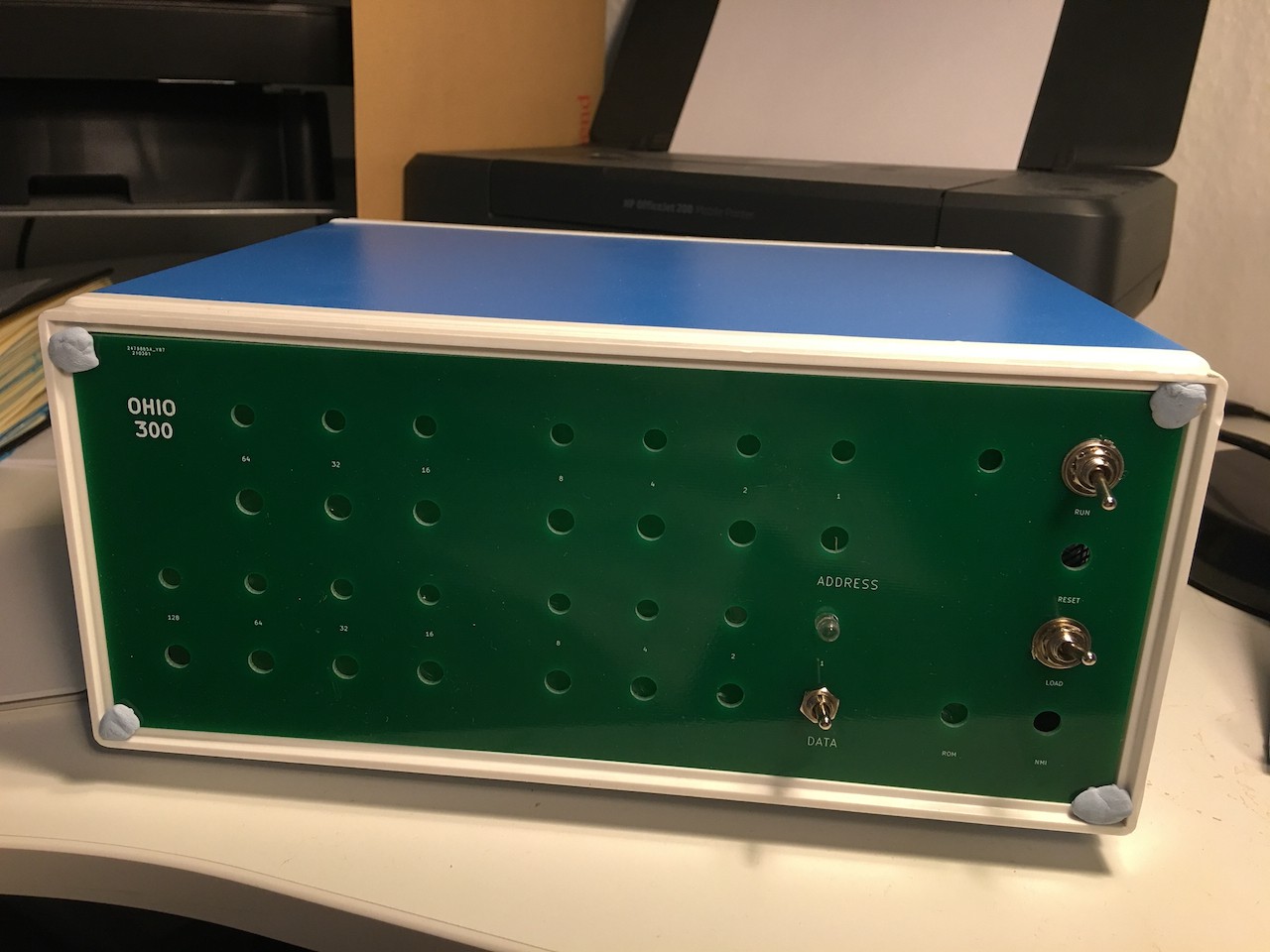
  • Make board large enough to use comfortably, small enough to ship cheaply

Stretch Project Goals

  • Include expansion points that might make it easier to add a ROM and address more RAM
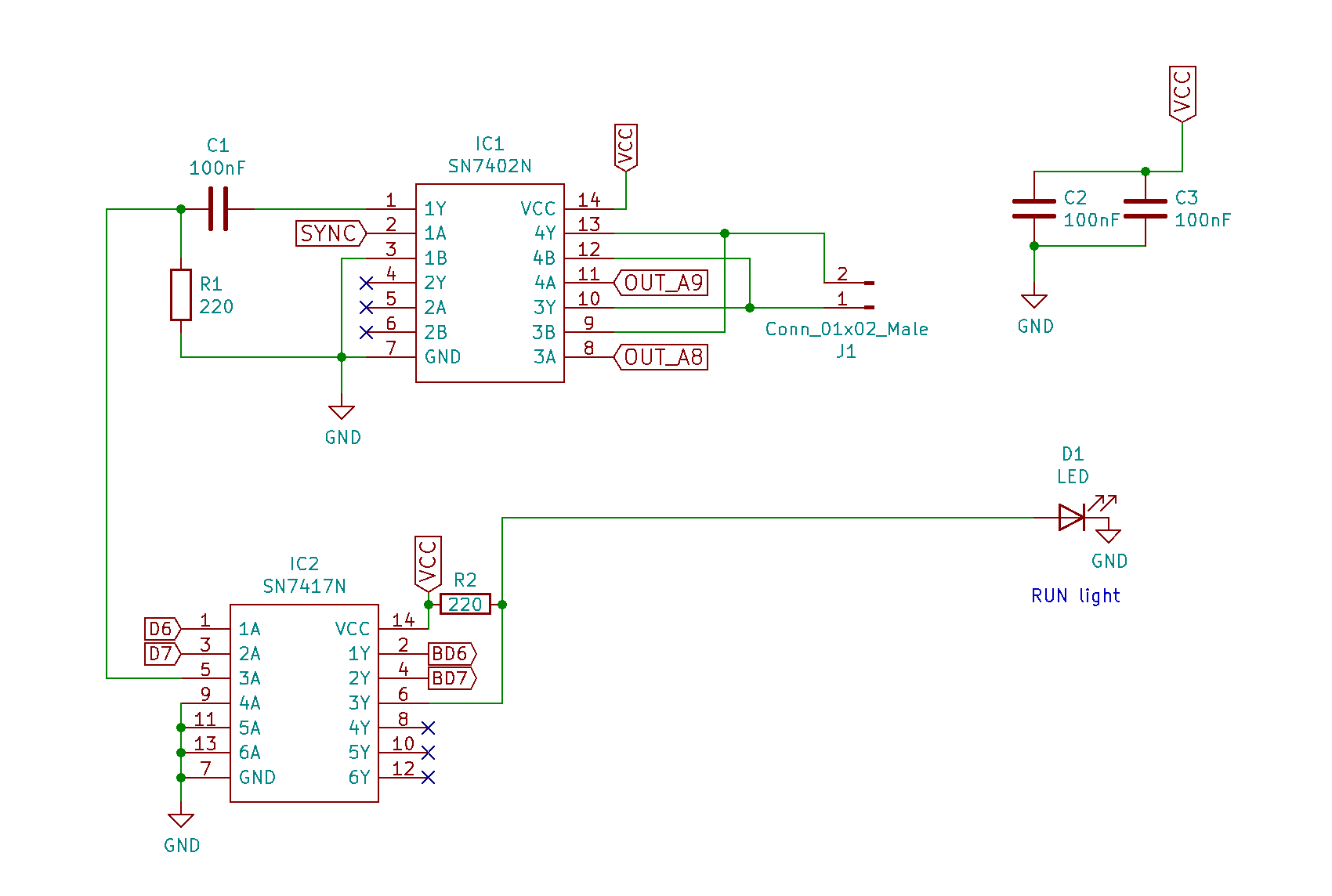
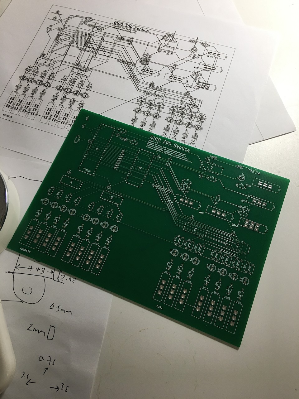
  • Replicate aesthetic of hand drawn traces

Financial Goals

  • Sell a few bare PCBs to cover costs of prototypes 
  • If sufficient interest, try selling a small number of kits

Personal Learning Goals

  • Learn basics of electronics
  • Learn how to read and draw a schematic
  • Learn basics of Kicad
  • Work through original OSI 300 manual with completed board and grok how it works

  • Is This Thing On?

    Tim04/24/2023 at 13:31 0 comments

    Thanks to a tricky couple of years I have not been able to continue work on this. Thankfully things are becoming a little more stable now and I finally have a little time to dust off and complete this project.


    I need to update the design to include my handmade fixes, correct the switch orientation to bring it into line with the original board.


    At the same time, I need to check that the components are all still available and if not, find replacements.


    KiCad has also at least one major release so I may need to tweak the project files to match.


    My time is still limited so this will be slow but I am determined to get a v1.0 out of the gate and wrap up this project. Watch this space!

  • 00000101 + 00001000 = 00001101

    Tim05/04/2021 at 17:14 0 comments

    Finally had some time to work on this thanks to it being another bank holiday weekend and after some frustration I have got the latest version (0.6) of the board working. Above is the result of the second exercise in the manual.

    Toggling in code by hand is hard work and ridiculously easy to get wrong. It is however helping me to develop a more intuitive understanding of lower level coding and is exactly the kind of masochistic pleasure I was hoping for when I embarked on this project!

    Those paying close attention may note that the control switches in v 0.6 do not match the historical design. In the next iteration, I will fix this and label their modes explicitly as I have done here temporarily by using a labeller. The Ohio Scientific Model 300 uses the front copper layer of the PCB for the little on-board documentation there is but since we have the luxury of a silk screen it seems worthwhile diverging from the original in this way.

    The first version (0.5) of the board was a mess. I had confused the buffered address lines with the address lines leaving so little functioning that it was not even good enough to test. (I could set and read values to one fixed address in RAM and that was it.) This current version (0.6) is much better and I was able to set and read values in RAM without too much of a problem using the switches - once I'd fixed a floating address pin - however I was not able to get the CPU to run any code. 

    I was not sure where to begin so first I decided to try to work out what exactly was going on as a first step towards working out how to fix it. Inspired by the Ben Eater videos, I ordered a cheap Arduino Mega clone, put the 6502 on a breadboard and used the Arduino to log the changing signals. It became clear that the 6502 was - sometimes - successfully reading the program counter value from the reset vector and was jumping there but was never able to read the value stored at that address.

    I was very confused and decided to write some more code to explore this, planning first of all on isolating the 6502 and emulating the RAM so I could confirm that I had not accidentally killed the chip during my various ham fisted experiments. To do so I needed to return to the data sheets to better understand the exact sequence of signals the 6502 expects during a reset and as I studied them it suddenly struck me that the new W65C02S that I am using has a BUS ENABLE (BE) pin which is not present on the old MOS 6502 used in the original design. I had left that unconnected and the fact that it was floating would explain why the CPU could sometimes read the address and data lines and sometimes failed to do so.

    I connected it to the RDY pin with a bodge wire on the back on the PCB and as if by magic the board now works! 

    (In the photo you can also see that I have also manually tied A7 to ground: I experimented with having an extra switch connected to A7 and when I removed it, I accidentally left the pin floating.)

    I'll carry on testing when I get time but I'm pretty confident now that the the next version of the PCB should be the last. I don't think I'll be adding any extra address switches as now that I have experienced the frustrations of doing so I cannot imagine anyone wanting to toggle in more than 128 instructions by hand.

  • 3D View from Kicad of v0.6

    Tim04/05/2021 at 14:18 0 comments

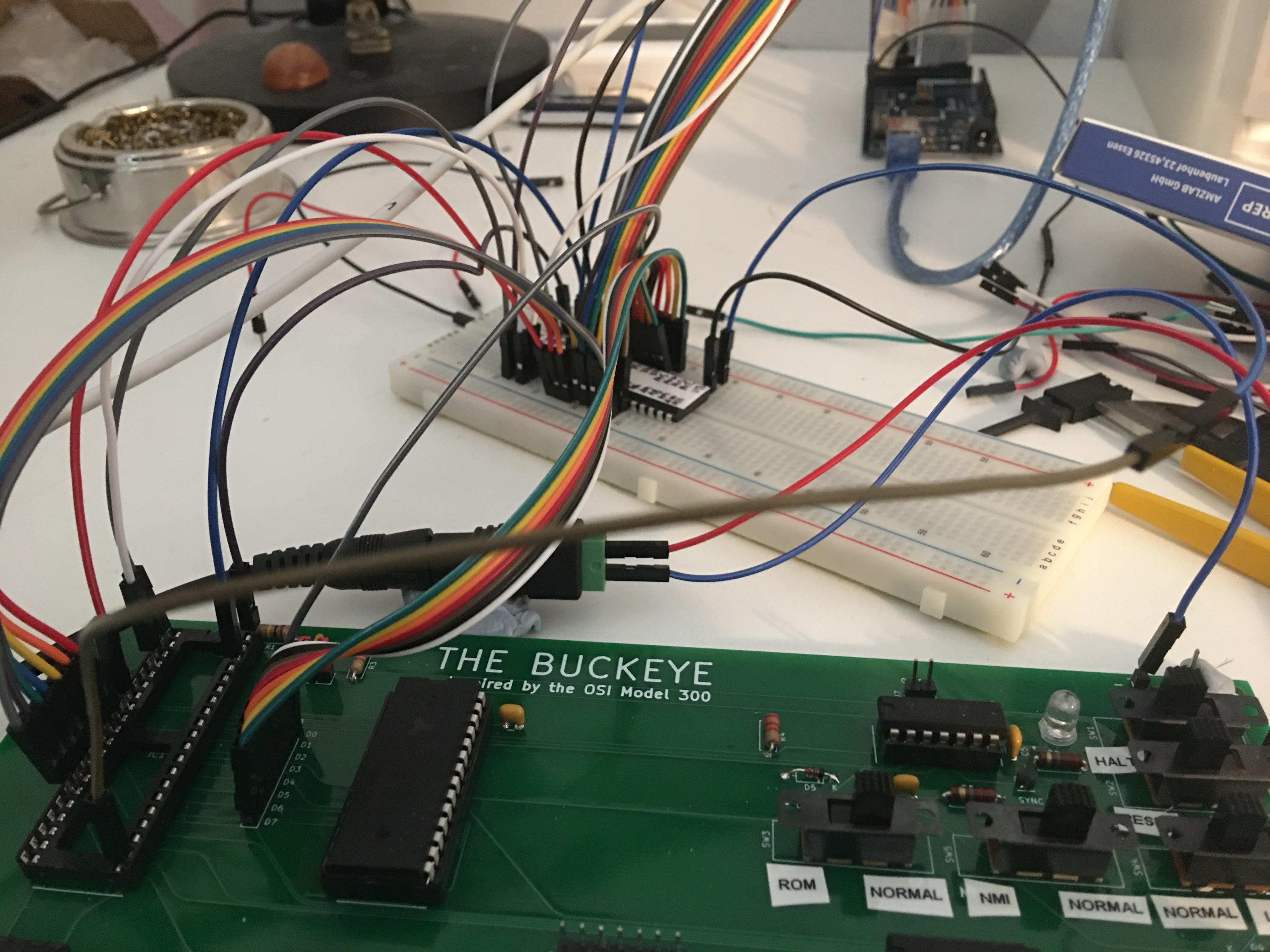
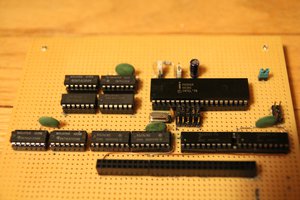
    With time off over the bank holiday weekend, I've made some progress.
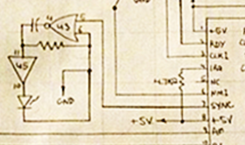
    Version 0.5 had a lot of errors - some trivial, some show stopping. I've now finished designing v0.6 that corrects all of these and will send it off for manufacture later today once I've checked it through. 

    I have redesigned the board several times between this and the last version in addition to fixing the errors I found. I have finally settled on a width that is proportionally larger than that of the original so that there is space in a future iteration to squeeze in 13 address switches without having to redraw everything.

    I suspect from pictures that the OSI Model 300 had no solder mask layer which increases the salience of those beautiful, swooping, hand-drawn traces. I have not gone so far but I have curved a few of the traces on the front of this one as a nod to the aesthetic of the original. 

    I am naming the board The Buckeye in honour of Ohio, home of Ohio Scientific. 

    Once I have tested this iteration I am going to start looking at expanding it. I already have some ideas. I'd like it to be possible to partially populate the final board and use it like an OSI 300 before adding further elements like a ROM so that people can build and use it in stages, exploring each before moving onto the next. First though I need to be certain that the core OSI 300 behaviour is working as it should.  

  • RUN, RUN, RUN

    Tim03/15/2021 at 13:11 0 comments

    I cannot test the physical board right now but I can think through the problems I was having.

    This is the relevant part of the circuit that drives the RUN light in the original schematic. 

    And this is how it looks in my schematic:

    Christopher at randomvariations describes it as follows with the abbreviated familiarity of an experienced engineer:

    "The final chip, a 7402 (quad NOR,) inverts the SYNC line, driving an RC network to stretch it, before it is finally buffered to drive the run LED. "

    If I have understood correctly, the SYNC output pin of the 6502 pulses each time an op-code is fetched. SYNC is therefore low when the 6502 is not running and low between pulses. The 7402 inverts the lows (as 1B is tied low so the NOR becomes effectively a NOT) so that the LED is driven high (via the 7417 buffer). The capacitor slowly charges while SYNC is low / IC1 pin 1Y is high and the stored charge smoothes over the instants when SYNC is high /  IC1 pin 1Y low so the LED should be lit continuously.

    The fact that the LED is not lit suggests that either this part of the circuit is wrong and/or that the SYNC signal is always high. This should be my next point of investigation.

  • Initial Testing of v0.5

    Tim03/14/2021 at 20:59 0 comments

    While soldering up the first PCBs which I have optimistically versioned as v0.5 I found a number of errors on the silkscreen - several missing resistor and diode values and, more confusingly, I had managed to swap the DATA and ADDRESS labels. It would also be helpful to label the power pins. The footprints however were fine and everything was easy to solder although the resistors were a little cramped and given how much space this board has I could possibly be a bit more generous here. For a first board though, it's okay.

    With 5V powering the board, there's about 4.3V across each IC - except for IC6 and IC7, the SN7417Ns that buffer the address lines and which are connected to ground when the RUN switch is connected to ground. These also have about 4.3V between the VCC and ground pins when the RUN switch is connected to 5V. I expected the values to be closed to 5V and wonder if this might be a problem.

    On my replica, the RUN switch is connected to ground when it is to the right. I get the impression from the OSI Manual that in the original this was the other way around so once I have confirmed this is the case I will fix on the next iteration.

    With no ICs installed the RUN light stays on all the time. 

    Once the SN7417Ns and the SN7042N are added, the RUN light stays off. All the data and address LEDs are on when RUN is to the left (connected to VCC). When RUN is switched to the right (connected to ground) the LEDs for data and address can be toggled on or off by the switches.

    When the ROM switch is to the left, the data LEDs cannot be changed by the switches. They are not completely off however - there is a very faint glow. I am guessing I need to increase the resistance.

    When the LOAD switch is to the left, the data LEDs cannot be changed by the switches.

    When RSI is switched left, 5V is asserted on the RESB pin on the CPU.

    When NMI is switched left, 5V is asserted on the NMIB pin on the CPU. 

    So far, so good, more or less.

    Adding the CPU and RAM exposes a problem. The data LEDs which I would expect to display random values for each address are mute. It seems unlikely that every value in the RAM is 00000000 - unless I have a dead chip. More likely the read enable logic is not functioning as intended or the RAM is not seeing the address that I am setting with the switches. I didn't however have time to test more closely what was going on at the RAM pins or the CPU.

    I noticed some flickering when I physically moved the board and then I saw some data LEDs randomly lighting up which suggests a poor connection somewhere or a short circuit. There were a number of solder splats and some flux residue on the PCB that could potentially cause shorts so I've removed the ICs and given the board a scrub with IPA followed by distilled water. I am going to leave it to dry out thoroughly overnight. I will hopefully find time to continue testing later in the week.

    I should probably have touched up the solder joints again before cleaning the board but that can be for another day.

    One thing that has become clear to me is that I am not 100% clear in my mind about the expected behaviour of the circuit which of course makes it impossible to test until I have worked this out for myself. This is work I should have done before getting to this point but the whole experience is a learning one and I will remember that for the next time. In truth, I should probably have breadboarded the circuit rather than jump into manufacturing a PCB but I find breadboards intensely frustrating and PCB manufacture is now so quick, cheap and easy that I skipped that step. I hadn't expected this to work flawlessly without any issues and I am fairly confident that I should be able to work out what is going on and fix it. More importantly, I am also having fun!

  • First Iteration Boards Have Arrived

    Tim03/10/2021 at 17:30 0 comments

    The first set of boards have arrived! I won't have time to add components and test this before the weekend but I have confirmed to my satisfaction that the footprints for the switches I designed are correct.

    When I submitted the gerbers for manufacture, I also decided to whip up a quick front panel design in FR-4 as well and amortise the shipping costs. This will replace the front panel of 250 x 190 x110mm metal junction box, an enclosure that is large enough to hold the Ohio 300 Replica PCB. 

    I got the mounting screw hole size wrong - hence the blutak holding it in place - and will fix that in a later iteration once I have had a chance to explore any usability issues while using this. The switch and LED hole sizes though are mercifully correct.

    This is intended as a quick proof of concept only and I'm immediately very happy with it. I think toggle switches on a vertical panel will be more fun than slide switches on the horizontal PCB and this set up will be good enough to play with until I finalise the design. I've ordered more toggle switches and am thinking about a second PCB to hold the LEDs in place.

    First though I need to check that the main PCB works as intended. Updates to follow.

  • 3D View from Kicad of v0.5

    Tim03/04/2021 at 11:59 0 comments

    3D view from Kicad. I haven't designed 3D models for the switches or the chips - that's a lower priority learning task on my list. 

  • Hit it!

    Tim03/03/2021 at 21:12 0 comments

    It took nine or ten months from first having the idea to making a serious stab at realising it. Some of that time was spent learning the basics of Kicad, trying to get my head around water analogies about the motion of current through a circuit and feeling simultaneously exhilarated and intimidated about how much there is to learn. It's only in the last two to three months that I've dedicated my small amount of free time directly to making it.

    A first attempt at redrawing the schematics I found online at http://retro.hansotten.nl/6502-sbc/osi-300-trainer/ led to a drawing I did not understand with over 100 DRC errors I did not understand either. I finally scrapped it and started again, trying to break the circuit down into sections I could comprehend, simplifying where necessary (such as only having one data switch) and only adding more sections (or the missing switches) once I was confident what I had was correct. This confidence was sometimes misleading and it wasn't unusual to discover that I had made mistakes but slowly over a couple of weeks a schematic emerged from this process that I think I understand and I think will work. Although I won't be surprised to find it doesn't.

    The original OSI 300 is 10 inches by 8 inches with beautiful hand drawn traces and lots of empty space, at least as far as I can tell from photographs I've found online. I have never seen one for real. If things go very well, I might be tempted to try emulating this hand drawn look in a later iteration but for now I am just going to focus on getting the board to work. 

    I've preserved the ratio and used large switches and 5mm LEDs like the original but the board is smaller so that the unpopulated PCB will fit in an A5 envelope. This will make it easier to ship if I sell them to people who don't want to manufacture their own. I will also put the schematics and Kicad files up online once it's finished so people can make their own and or use it as the basis of their own projects.

    Designing custom footprints for the switches I have found was fun. I am not 100 percent certain that they will work. just as I am not certain that the circuit is correct, but I have reached the point where I am willing to get a test PCB made so that I can add the components and start to debug any problems. I have sent the gerber files off to be manufactured and will update once the first PCBs arrive.

View all 8 project logs

Enjoy this project?

Share

Discussions

Geoff wrote 12/12/2021 at 03:35 point

Hi Tim, I found your project while searching for information about the OSI 300. I wanted to try and recreate it as well, but I my knowledge of electronics is self taught. Is your project still ongoing?  

  Are you sure? yes | no

Steve L wrote 03/09/2021 at 01:16 point

There really is an "art" to hand drawn PCB's.  True story: I worked for a company where the PCB designer was a semi-retired commercial/fine artist who graduated from the Art Institute of Chicago, who became familiar with PCB design late in his career. His double sided boards were works of art. Surprisingly dense, double sided, and not  a single straight trace for a single connection. My manager claimed that his boards could beat the CAD available in the early-mid 80's for passing FCC RF (a real concern back then).

  Are you sure? yes | no

Tim wrote 03/10/2021 at 13:28 point

Hi Steve. I can believe it. I can imagine being good at calligraphy, for example, would stand you in good stead for hand drawing traces. I have been looking into how I would do this while waiting for the PCBs and am excited to try it.

  Are you sure? yes | no

Steve L wrote 03/09/2021 at 01:08 point

I ordered one of the original versions "back in the day", and I was unhappy with it because although it was fairly expensive for a broke college student, it didn't have plated-through holes, This was starting to become "table stakes" in the industry. I sent it back, saved up, and bought a Jolt.

  Are you sure? yes | no

Tim wrote 03/10/2021 at 18:34 point

Good upgrade! I've just bookmarked the retro.hansotten page on the Jolt to study later http://retro.hansotten.nl/6502-sbc/jolt-and-super-jolt/jolt/ as it looks like a fascinating system. One small titbit of interest from that page that you probably knew already - the Jolt was used in the first wirewrapped prototype Atari 2600 VCS.

  Are you sure? yes | no

Owen wrote 03/08/2021 at 20:31 point

I remember seeing this(*) in one of my magazines (possibly 'Hobby ELectronics') when I was 9; it seemed awesome! the future!! etc.. a kind of Micro:Bit of it's day.

(*) Ok, 44 years makes it hazy, but if not this it was something similar, and definately 6502 based, I knew my CPU's better than my Dinosaurs back then.

  Are you sure? yes | no

Tim wrote 03/10/2021 at 13:37 point

Hi Owen. It clearly left an impression on you - or a similar board to this did. That feeling of glimpsing the future is very powerful. I still feel it today - even though we are living in one of those possible futures glimpsed back then. There's also something very raw and direct about these old trainer boards that really appeals to me. I (perhaps romantically) wonder if they are still of value for youngsters to teach them about how computers work at an even lower level than microcontrollers do. I'll be trying to persuade my nieces and nephews to try once I have a working replica. 

  Are you sure? yes | no

Dan Maloney wrote 03/04/2021 at 19:43 point

Love your PCB design, but I'm sorry, the hand-drawn traces on the original are just to die for! It would be cool if one of the current crop of design programs had a "retro mode" for making PCBs look like they used to look.

  Are you sure? yes | no

Tim wrote 03/04/2021 at 20:36 point

Thanks Dan. I absolutely agree. The original hand-drawn traces are beautiful! A retro autorouter would definitely make it easier to replicate this look.

  Are you sure? yes | no

Similar Projects

Does this project spark your interest?

Become a member to follow this project and never miss any updates