Close
0%
0%

PewPew S2

Even better PewPew

Similar projects worth following

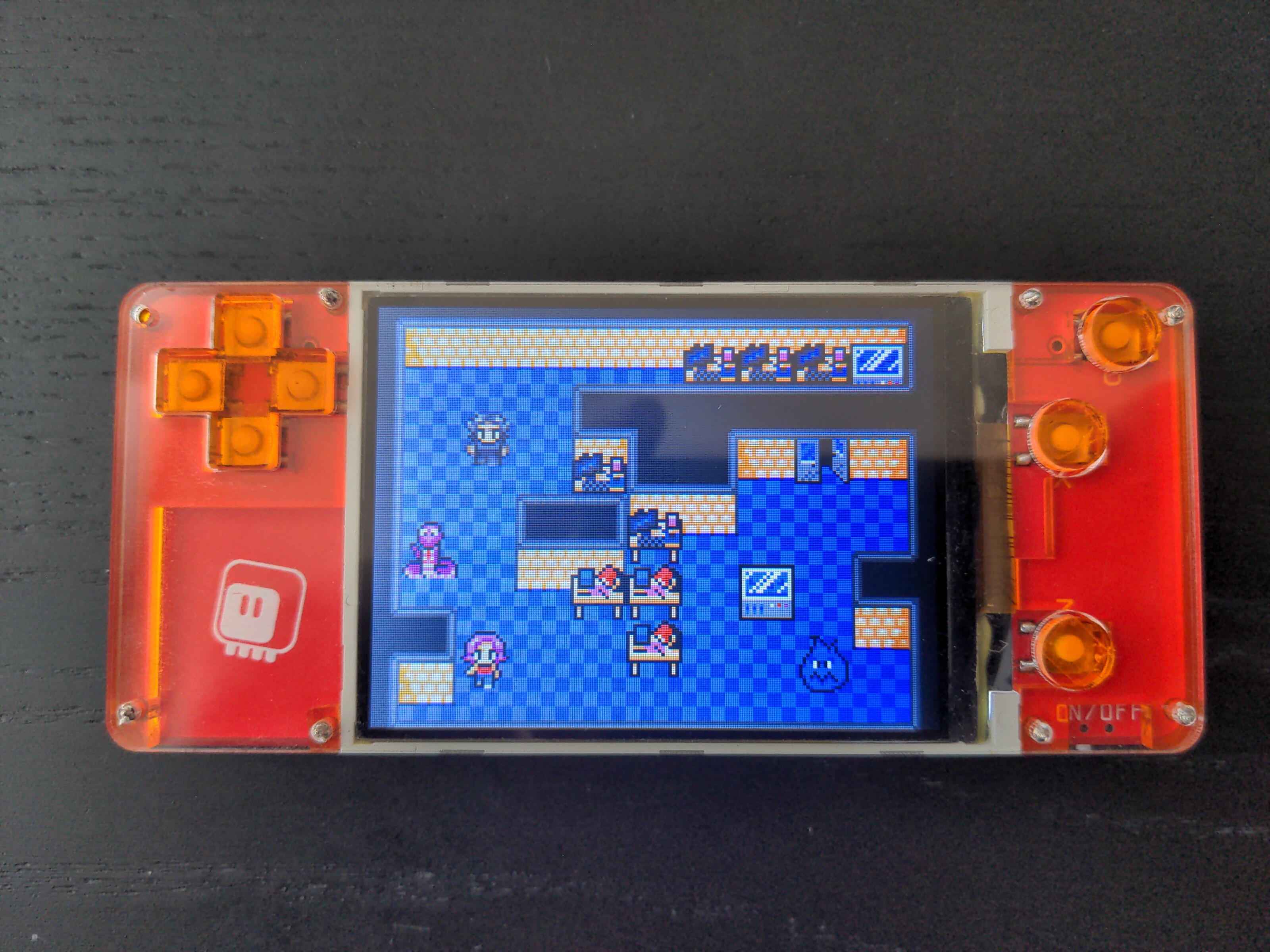
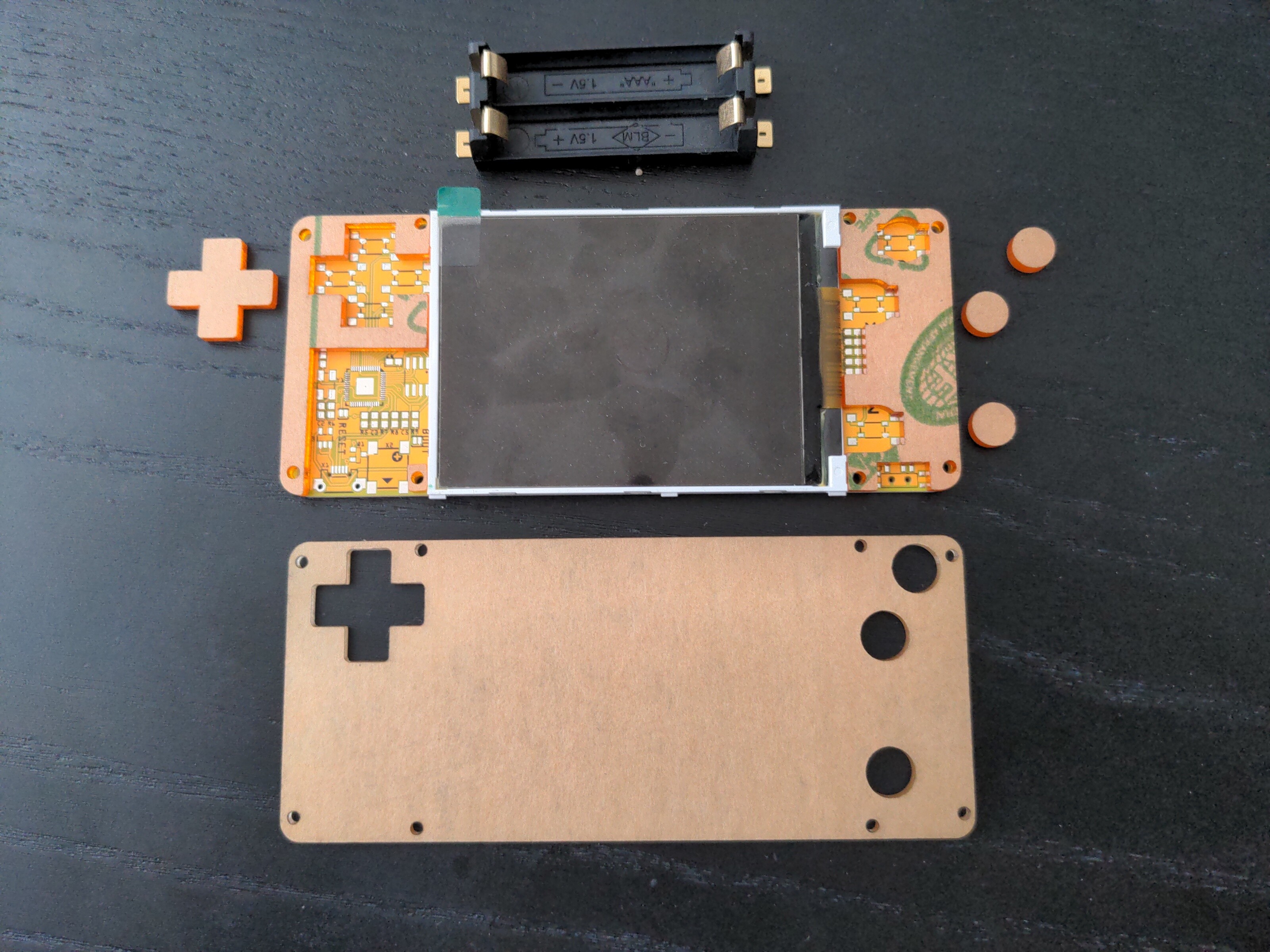
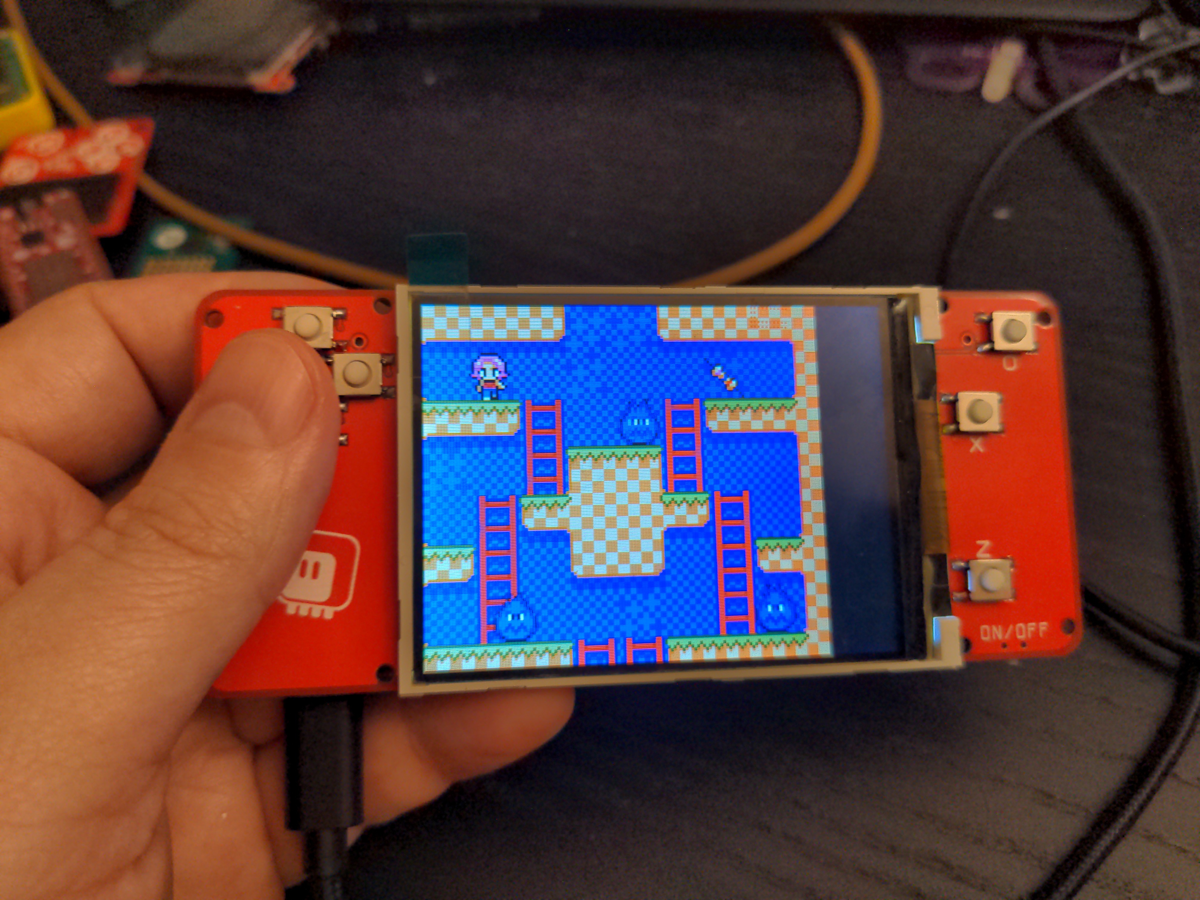
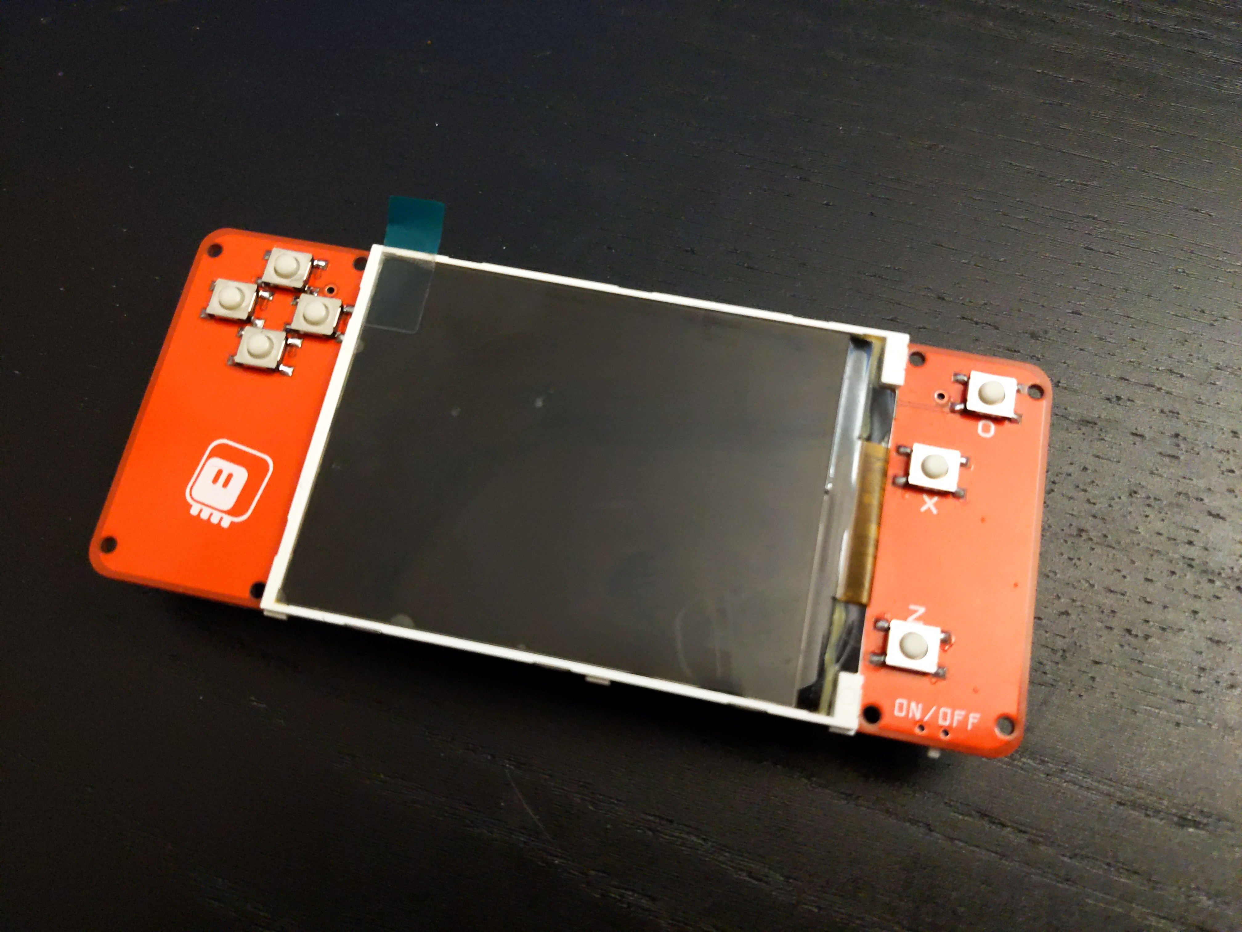
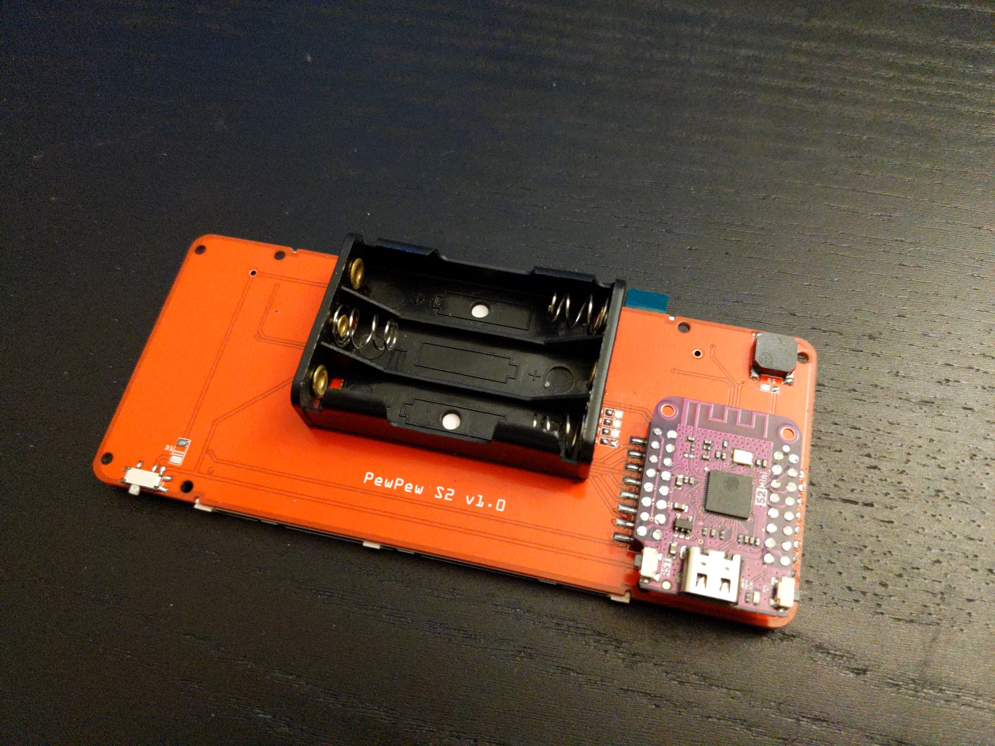
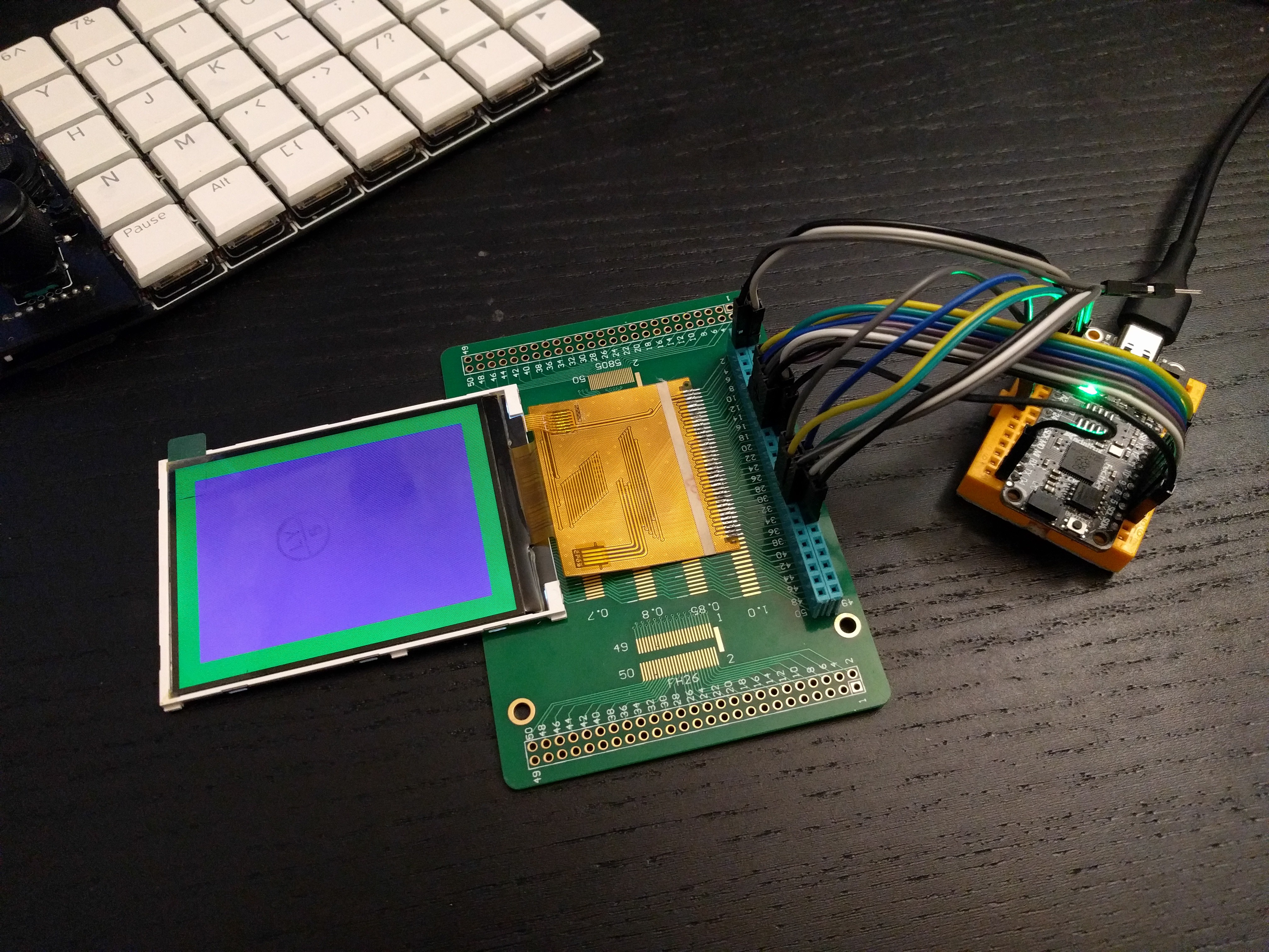
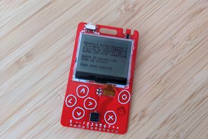
I'm still working on improving the PewPew series of devices. #PewPew M4 is pretty close to my ideal, but it would be nice to have something with a little bit more luxury: larger screen, volume control, more RAM memory. The Raspberry Pi Pico module seems to be a good vehicle for this: it has enough pins to use parallel interface to drive a bigger screen fast, and it has a lot of memory for such a tiny chip.

It won't be as cheap, of course — the screen alone is three times more expensive — but I think I can still keep the price reasonable.

  • A Case

    deʃhipu08/18/2022 at 20:19 0 comments

    Because I'm working on the RP2040 version of this, together with the PCBs I also ordered a laser-cut case in the same style as the #PewPew M4 has. And since the dimensions are the same, the case also fits this board, so I now have a nicely encased console:

    The button caps are right now still on small pieces of two-sided tape, stuck to the buttons, but I plan to design two stickers that would go on the bottom of the transparent plate, sticky side up, to mask the display and also keep the caps in place.

    The case is basically two layers of laser-cut acrylic:

    In this prototype I made the holes for the screws in the transparent plate a bit too large, so I had to use bigger screws and insert pieces of wire into the holes for the thread to catch properly, but that is something easily fixed in the next version.

    There is no case on the back. The new board has its back completely clean (except for the battery holder), so it wouldn't make much sense, and anyways it wouldn't fit this board, because it uses more batteries and has the speaker and the microccontroller board on the back.

    It still improves the convenience and looks.

  • It's Alive

    deʃhipu03/03/2022 at 09:57 0 comments

    I had some time to add the remaining resistors to the build, and to compile a version of CircuitPython with my _stage module included. It all went without too much problems.

    I quickly copied the screen initialization for displayio from Adafruit's ILI9341 driver, and copied all the other bits for the ugame.py file from other platforms, and voila, we have a working game console:

    What's still left to do:

    1. tweak the display registers to get rid of flickering
    2. compile firmware with the display initialization included in C
    3. get the pwm audio to work
    4. think about a case, perhaps?

    All in all, the large display is super-nice, and I'm also very happy with the light but clicky buttons. The position of the S2 Mini module is not great, but I can't think of any better way to place it.

  • Prototype 1

    deʃhipu02/24/2022 at 21:50 0 comments

    The PCBs arrived, and I assembled one. The screen is  a really nice tight fit. The S2 Mini sticks out more than I would like — perhaps in the final version I will solder it flat to the PCB, without the headers. I still need to add all the resistors — figuring out their values is more hassle than I am ready for right now. I used super-light (7gf) clicky buttons this time, and I'm really happy with how they feel.

  • Restarting

    deʃhipu02/14/2022 at 16:18 0 comments

    I put this project on hold last time, but somehow I couldn't let go of the ideas, so now I'm back. As mentioned previously, the experiments with parallel display didn't work very well, and I have given up on that — but that same display is also available with an SPI interface — named Z320IT010 — and with a faster SPI clock of the ESP32-S2, it might still work well enough. I would use my #Stage, a Tile and Sprite Engine, which now has the option of scaling the display up, and not the slow displayio.

    I also decided to take a step back from designing a "product" that can be assembled by a fab house, and instead make a prototype that can be easily made at home. This, among other things, means using a development board, which simplifies everything considerably.

    Finally, I decided to try the portrait orientation. I went ahead and ordered the first PCB:

    We will see how well that works.

  • On Hold

    deʃhipu06/11/2021 at 21:15 0 comments

    Since my experiments show that using the parallel interface for the display doesn't make it fast enough to handle the bigger display, I don't see much point in continuing this project. The larger display with parallel interface was really the most important innovation compared to my other projects.

    I might resurrect it later on, if I find a way to speed things up, or maybe use a different microcontroller again. For now, I'm putting it on the back burner.

  • Parallel Bus

    deʃhipu03/25/2021 at 22:24 0 comments

    The displays arrived a few days ago, but I really didn't have the energy to get them working until today. Yesterday I found my Universal Display Breakout Board™ and soldered the display to it. Today I connected a Feather RP2040 to it, and tried to get it working. Turns out there are a couple of tricks to it.

    First of all, the IM0-3 pins are not broken out, so there is no way to switch the interface mode, and it comes in the 16-bit parallel mode by default. But wait a minute, the Aliexpress page said it was compatible with 8-bit mode, so how? I asked the seller, but before I got the answer, I noticed this little note on the screenshots of the datasheet at the product page:

    That, I assume, explains, in perfectly clear Chinese, how to switch the iterface modes. It even tells you which pins to use in each mode! I mean, probably. I don't read Chinese. But let's look closer at the display:

    Ah-ha! The aforementioned R16 and R8, and only one of them is populated. And that is a 0Ω resistor, if I'm not mistaken. So I only need to move it from R16 to R8 and that should switch the mode. Easy. Later the seller confirmed this, I assume this is direct translation of the above note:

    When R16 connect resistance, it is 16-bit interface, DB15-DB0 are useful (default 16-bit)
    When R8 connect resistor, it is 8-bit interface, DB15-DB8 are useful

    With that out of the way, there is one more trick. Have you noticed how it tells you that DB15-DB8 should be used in 8-bit mode? But the datasheet for ILI9341 says DB0-DB7... I wonder why they specified those pins in reverse order, hmm... Yes, of course the pins are reversed. What is labeled as DB15 is actually DB0, and so on. I feel really smart for figuring it out at first try, before I connected the wires.

    But no worries, I immediately felt less smart for making stupid off-by-one errors connecting the wires, so that's balanced.

    The final trick relates to the backlight LEDs. The pinout has two pins marked as LED-A, and five pins marked as LED-1 to LED-5. So logically, the two pins are common anodes (doubled so that you can put more current through the pins), and each of the five LED pins is the cathode of one of the five backlight LEDs. So in the final design, we will need a MOSFET on the anodes, and five resistors on the cathodes. Well, closer examination of the traces tells a different story. Both LED-A pins merge into a single trace — that is somewhat expected, even though that trace is no wider than others. But also all the cathodes merge into a single thin trace, and then split again near the display where the backlight is connected! That is some bad practice there, but at least that saves my four resistors, I suppose.

    With everything connected, a little bit of code:

    import displayio
    import board
    
    
    _INIT_SEQUENCE = (
        b"\x01\x80\x80"  # Software reset then delay 0x80 (128ms)
        b"\xEF\x03\x03\x80\x02"
        b"\xCF\x03\x00\xC1\x30"
        b"\xED\x04\x64\x03\x12\x81"
        b"\xE8\x03\x85\x00\x78"
        b"\xCB\x05\x39\x2C\x00\x34\x02"
        b"\xF7\x01\x20"
        b"\xEA\x02\x00\x00"
        b"\xc0\x01\x23"  # Power control VRH[5:0]
        b"\xc1\x01\x10"  # Power control SAP[2:0];BT[3:0]
        b"\xc5\x02\x3e\x28"  # VCM control
        b"\xc7\x01\x86"  # VCM control2
        b"\x36\x01\x38"  # Memory Access Control
        b"\x37\x01\x00"  # Vertical scroll zero
        b"\x3a\x01\x55"  # COLMOD: Pixel Format Set
        b"\xb1\x02\x00\x18"  # Frame Rate Control (In Normal Mode/Full Colors)
        b"\xb6\x03\x08\x82\x27"  # Display Function Control
        b"\xF2\x01\x00"  # 3Gamma Function Disable
        b"\x26\x01\x01"  # Gamma curve selected
        b"\xe0\x0f\x0F\x31\x2B\x0C\x0E\x08\x4E\xF1\x37\x07\x10\x03\x0E\x09\x00"  # Set Gamma
        b"\xe1\x0f\x00\x0E\x14\x03\x11\x07\x31\xC1\x48\x08\x0F\x0C\x31\x36\x0F"  # Set Gamma
        b"\x11\x80\x78"  # Exit Sleep then delay 0x78 (120ms)
        b"\x29\x80\x78"  # Display on then delay 0x78 (120ms)
    )
    
    displayio.release_displays()
    bus = displayio.ParallelBus(
        data0=board.D4,
        command=board.A1,
        chip_select=board.A0,
        write=board.A2,
        read=board.A3,
        reset=board.D24,
        frequency=62_500_000,
    )
    display = displayio.Display(bus,...
    Read more »

  • Display

    deʃhipu03/05/2021 at 13:19 0 comments

    The display can be considered the centerpiece of this device. It's the largest and most expensive component. Pretty much everything else is decided by its choice — the size, the shape, the connections, etc. So let's look closely what we have to choose from.

    I'm a huge lover of pixel art, and I want the games for this console to have large, visible pixels. That means, on one hand, that we want a display with a large diagonal, but also, at the same time, we want low resolution, so that the displayed pixels are physically large. Low resolution is also important for two other reasons: the less data we have to send to the display, the faster we can do it and the more time the microcontroller has for other calculations, and it's also much easier to learn about game development at low resolution, when you can actually see what is happening and can count pixels between things with your naked eye.

    This is why for #PewPew M4 I have settled on the 1.8" ST7735 display — with the resolution of 160x128, it's the largest pixels you can have, and the $4-ish price is also very nice. Unfortunately, 1.8" is still a bit small. So what can we do?

    What if we doubled the size of the pixels, and used a display with larger resolution? One immediate problem is that we would need to send four times more data per frame, on average. But what if we also switched from a 1-wire SPI to 8-wire parallel protocol? That's eight times faster, so it should still give us two times speedup!

    So what are our options for a doubled resolution? If we want our display to be cheap and easy to source, then we have basically two options: ILI9341 and ST7789V, which are both pretty much equivalent. They have 320x240 resolution, which is almost double of 160x128, except we lose those 16 pixels vertically. I think I can live with that. A little bit of browsing and looking around lets us conclude, that the largest ILI9341 display you can find is 3.2" diagonal — that is almost twice the size of the ST7735! As usual, there are variants with different interfaces, but considering we need parallel interface, I think the best for us is the Z320IT002 — a 3.2" display with 37 pins.

    Now, that we know the dimensions of the display, we can say a little bit more about the device we want to build. It needs to be at least 8.5cm wide, in order for the functional part of the display to be centered on it. I could place the buttons on the sides, for a Switch-like landscape mode, or under the screen, for a more classic Gameboy-like portrait layout — both should be wide enough to hold the device comfortably. However, if I went for the landscape mode, then the device would be wider than 10cm, which pushes us into the area of expensive PCBs. Anything that fits in 10x10cm is relatively cheap these days (including laser-cutting of the acrylic case), but going over that makes the price grow four times larger. I could make it use several smaller PCBs, but that's again increasing the price, as now you have to pay for two or more PCBs instead of just one. So let's keep it within the 10x10cm limit. What about the height? If we look for a "standard" size that is close to the 8.5cm width, we will find the ISO B7 format, also known as ISO/IEC 7810 ID-3, at 12.5x8.8cm. But that takes us outside of our 10x10cm comfort zone. So why not just keep the minimal required 8.5cm width, and make the height the same? Turns our we should be able to fit everything in that form factor nicely, as long as the Raspberry Pi Pico goes on the back of the device.

    By the way, that display is also available with a touch screen, but I think I'm going to ignore that option — it makes it a bit more expensive, makes the whole assembly thicker, and it would require me to rethink the whole case — I could no longer have transparent acrylic in front of the screen! Also, I think it would unnecessarily complicate the games, and shift the focus away from what I want to teach with this.

  • Challenges

    deʃhipu03/05/2021 at 11:16 0 comments

    You might think that there is absolutely nothing challenging in simply connecting a screen and a bunch of buttons to a microcontroller development board, and you would be right. I have done it so many times by now, that it should be simple even for me. However, as the saying goes, the devil is in the details.

    First of all, this is the first time I'm using the Raspberry Pi Pico development board, and it's not like other development boards out there. On one hand, it has a build-in buck-boost converter, which makes it nice to use with the batteries, on the other hand it doesn't have the power switching circuitry that disables battery when USB is connected — so there is an extra bit of electronics with a MOSFET needed to be added. I'm worried about this, because I have always had bad experiences with power circuits like that.

    Next is the audio output. On my previous consoles, there simply was a DAC pin, where you connected the speaker or the amplifier and speaker, and you were done. Here the audio output is PWM-based, and I will need a low-pass filter to smooth it a bit before feeding to an amplifier. Plus, I want to have a volume control, but the only small sliding potentiometer I found is around 9kΩ, which is a bit low to just make it a simple voltage divider. Some experimenting will be needed, and again, analog circuits are scary.

    Then there is the display backlight. It uses four internal LEDs, and I could do what I did previously, just connect them straight to the battery with a current-limiting resistor. But it would be nice to have backlight control, and even a light sensor, to adjust the backlight brightness to the environment. More scary transistors and analog circuits to worry about.

    Finally, and that is going to actually take the most work, there is the question of design. Selecting the best (both in terms of functionality and price) components, and finding an arrangement of them that is both functional and aesthetically pleasing. Designing the shape of the device, its case and its controls. I have already done some work on this, much much more remains.

View all 8 project logs

Enjoy this project?

Share

Discussions

VermaAyush wrote 09/03/2022 at 01:27 point

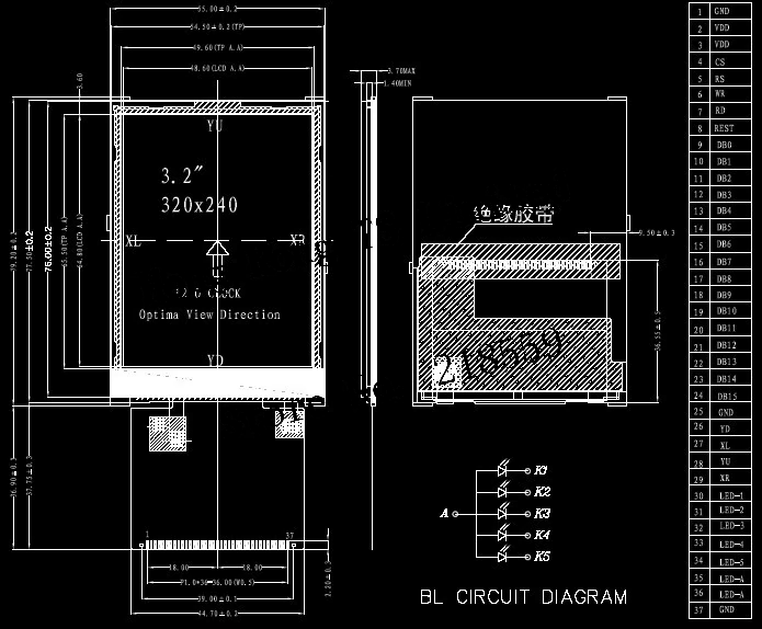
helow great project what is the model no of lcd please tell me

  Are you sure? yes | no

deʃhipu wrote 09/03/2022 at 09:43 point

I discuss it in this log: https://hackaday.io/project/178061-pewpew-s2/log/203159-restarting

  Are you sure? yes | no

Makerfabs wrote 03/18/2021 at 07:09 point

i am also making something on Pico...

  Are you sure? yes | no

Similar Projects

Does this project spark your interest?

Become a member to follow this project and never miss any updates