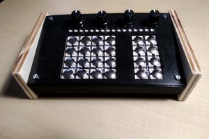
• 1
    Step 1

    Story

    In this tutorial i will show you how to make a simple color sorting machine machine using Arduino and TCS230,TCS3200 color sensor with servo motors.

    In this project Color sensor detect the color of candy and generate output in this output sensor data transfer to arduino arduino will process those data according to code uploaded in it and command servo to move and sort color candy on basis of there color.

    Before we proced further I would like to tell you about JLCPCB.COM.

    JLCPCB are the leader in PCBC manufacturing they have a world class PCB production line, that ensure the fast and Quality PCB production in really very affordable rates. if you have any PCB need please try JLPCB.COM

    First watch the video of Machine

    Step 1: Video

    Step 2: Components Required

    1) Arduino NANO : - http://amzn.to/2v6ICSm

    2) Color sensor :- http://amzn.to/2vHvosg

    3) Servo motor :- http://amzn.to/2vHvosg3)

    4) Cardboard

    5) Color candy

    Step 3: Electrical Drawing

    1 / 5

    Do wiring as shown in figure

    Color Sensor Arduino

    SO-------------------------D2

    S1-------------------------D3

    S2-------------------------D4

    S3------------------------D5

    OUT----------------------D6

    VCC---------------------5V

    GND--------------------GND

    Connect TOP servo signal wire at D7 pin of arduino

    Connect Bottom servo signal wire at D8 pin of arduino

    Step 4: Machine Assembley

    Download the attached PDF file for complete dimension of machine

    Bring some cardboard pieces draft the model as per given dimension on cardboard sheet

    carefully cut those pieces make sure are accurately cutted to avoid any malfunction during machine run.

    Glue all the parts as shown in figure,

    To make transparent feed tube i used empty cold drink bottle cut it and took a piece out of it

    and fold that sheet in tube like shape and secure with transparent, keep the diameter of tube according to the size of candy so they can pass through it easily at same time not also very loose..

    FT52AULJ5K6UKGC.pdf

    Step 5: Basics of Color Sensor TCS230,3200

    1 / 5

    The TCS230 programmable color light-to-frequency converter combines configurable silicon photodiodes and

    a current-to-frequency converter on single monolithic CMOS integrated circuit. The output is a square wave (50% duty cycle) with frequency directly proportional to light intensity (irradiance). The full-scale output frequency can be scaled by one of three preset values via two control input pins. Digital inputs and digital output allow direct interface to a microcontroller or other logic circuitry. Output enable (OE) places the output in the high-impedance state for multiple-unit sharing of a microcontroller input line. The light-to-frequency converter reads an 8 x 8 array of photodiodes. Sixteen photodiodes have blue filters, 16 photodiodes have green filters, 16 photodiodes have red filters, and 16 photodiodes are clear with no filters. The four types (colors) of photodiodes are interdigitated to minimize the effect of non-uniformity of incident irradiance. All 16 photodiodes of the same color are connected in parallel and which type of photodiode the device uses during operation is pin-selectable. Photodiodes are 120 µm x 120 µm in size and are on 144-µm centers.

    Step 6: Final Step (Loading Code & Sensor Data Study)

    1 / 2

    Before going further we must know what vale will sensor gives when different colors are take in fornt of the sensor

    So first wire the sensor and arduino as shown in picture you may skip to attache those servo at this point of time.

    Load the code attached here to your arduino board

    open the serial monitor

    You are getting some value like

    R= ** G= ** B= **

    ** are any numbers

    now bring color sheet in front of the sensor you will see the RGB numbers are change and keeps repeating as soon as you keep that color sheet in front of that sensor.

    you will get different set of RGB numbers for different,

    so it is clear that sensor detect different colors and gives different value.

    now we have to write down the RGB value for the color which are going to use in project

    for example when i bring YELLOW color in front of sensor i get

    R=22 G=29 B=32

    so i can say that

    if (R>17 & R<27 & G>25 & G<34)

    COLOR=YELLOW;

    here i kept margin of +-5 for RGB values to compensate the fluctuate sensor values.

    in this way take the readings of different colors which you need to use and add those values in code at this place

    if(R<25 & R>15 & G<33 & G>23) {color = 1; // YELLOW }

    if(R<55 & R>45 & G<49 & G>39) {color = 2; // GREEN }

    if(R<70 & R>60 & G<10 & G>20){color = 3; // PINK }

    if(R<7 & R>11 & G<21 & G>35){color = 4; // Red

    and upload the code connect the both servos fix all the required components load the color candy in tube and your machine is ready to short the candy of different colors.

    FFHMNRHJ5K6UMDT.ino