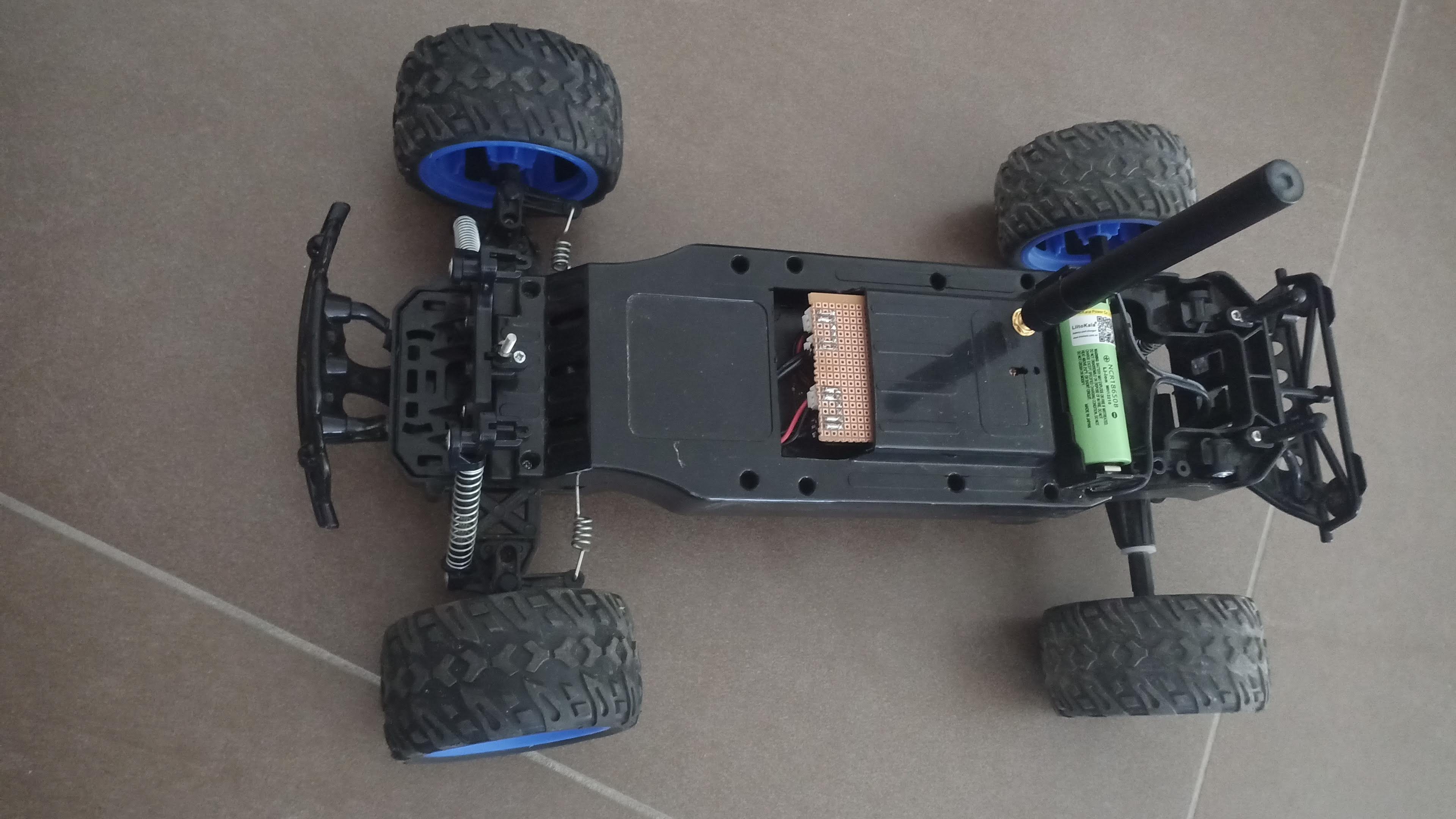
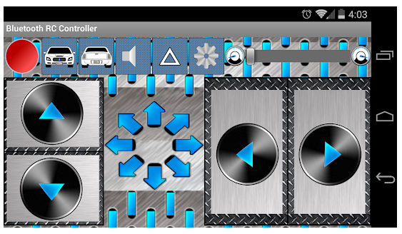
• Tires

    Christoph Tack10/04/2021 at 17:06 0 comments

    I've long overlooked an issue with the tires.  These are not fixed well to their rims.  The tires easily slip over the rims when the car breaks or accelerates too briskly.

    CA-glue along the edges of the rim solves that issue.  The short-stop behavior of the car has improved.  The acceleration should also be improved, but that's harder to notice/measure.

  • Results

    Christoph Tack07/22/2021 at 19:01 0 comments

    Range

    The range is greatly increased.  Now it's at least 80m.  That's more than enough for such a small car.  At such a distance it's hard to figure out what way the car is pointing.

    Speed

    It doesn't seem to drive faster than before.  I'm a bit disappointed in this.

    Control

    The original controller was of a very low quality.  The steering of left and right didn't work well.  It's easier to control with the app on the smartphone, although that one lacks tactile feedback.

    Firmware

    When the car drove out of range, it simply continued what it was doing.  A dead man's switch had to be added in firmware.  One second after reception of the last command, the car will stop automatically.

  • Motor control section

    Christoph Tack07/02/2021 at 12:25 0 comments

    The ESP32 development board has an AMS1117-3.3 linear regulator.  The datasheet announces this regulator as LDO, while the dropout voltage is typically 1.1V!  A quiescent current of typically 5mA is neither something to write home about.  But that's what is.  Don't use this ESP32 board for a low power application. 

    To get a stable 3V3 on the ESP32, the battery voltage must be boosted to 5V (or 5.5V).  The same boost converter type that also powers the motor shields will be used here.  It's mounted between the ESP32 and the breadboard.

    An extra 470µF/10V is added on the 5V input of the ESP32 board.  Just in case.

    The ESP32 uses two GPIOs to control each DFRobot motor driver.  There's a 3pin JST-EH to power the ESP32 with the Li-Ion cell.

    The motor controllers are powered by the boost converters (bottom JST-EH on each motor driver).  The other JST-EH connector is connected to the DC-motor.

    Top side
    Bottom side

    Electric connections to the main body

    All connections are made using JST-EH connectors.

    There's a 3-pin connector for powering the ESP32.

    There are two pairs of 2-pin connectors for powering the motor controllers.  The remaining two pairs with red/black wire are connected to the two motors themselves.

    Main body wired, ready for mounting controller circuitry

    Controller PCB mounted

    In the background, the shell is visible with the antenna mounted in it.

    Shell closed

    The controller board requires more space than the original electronics.  Using a Dremel tool, I made a cutout in the shell.  The cutout is too big, but at least the circuitry fits easily.

    The 18650 battery clip is also mounted onto the shell, as well as an RP-SMA antenna pigtail cable for the LSR antenna.

  • Power management section

    Christoph Tack07/01/2021 at 19:48 0 comments

    Power distribution board

    The power from the Li-Ion is connected to the leftmost JST-EH.  There's a 2pin JST-EH for the power-interruption switch between the battery and the battery protection board.  It might be wiser to connect the battery monitor circuit directly to the battery and then put the power-interruption switch.  I'll have to find out later.

    The three bottom 3-pin JST-EH connectors connect to the two boost converters and to the ESP32.

    Li-Ion protection

    A test using 2x 1S/3A-Li-Ion protection from AliExpress (€0.30+€1.15 shipping) showed that it was inadequate.  The current limit is too strict. 

    • UVLO = falling voltage: 2.5V, rising voltage: 2.84V (tested)
    • Over voltage lockout = 4.25V (tested). The FET goes into LDO mode, limiting voltage to 3.77V.

    A better option would be to order this battery monitor system (BMS) instead.

    Top view
    Bottom view

    Motor Power supply

    The traction motor will run on 12V, the steering motor on 7V.  Two boost converter modules will be used.  The quality of those modules is not great.  One gave hiccups when the traction motor went full power.  Replacing the module was the quickest fix.  I bought them as MT3608 boost converter modules.  The label on the package is "XT1208".

    Power management board and two boost converter modules mounted into the battery compartment.

    The two boost converter modules are fixed with 3M VHB-tape.  It sticks well.  It's thick so it can be used on uneven surfaces.  It's also easy to remove.  It doesn't leave traces of sticky glue (unlike duct tape which is a hell in this regard).

  • Remote control

    Christoph Tack06/05/2021 at 12:47 0 comments

    Bluetooth

    Bluetooth doesn't require a custom remote control.  You can use a smartphone.

    The aforementioned project uses a HC-05 Serial Bluetooth module.  This module won't be used here, because the ESP32 already has Bluetooth on board.

    It doesn't take more than loading the code from "ESP32 Bluetooth Classic with Arduino IDE – Getting Started" into the ESP32 and execute it.  The Bluetooth RC Car Android app willingly connects to the ESP32.  Serial data is coming in.  We got this working!  This went easier than I thought.

    The problem with this solution is that there's no tactile feedback.  You have to look at your fingers, so that you know where to put them and at the same time look at the car.  Practice makes perfect, I guess.

    Car

    To keep things simple on the software side, we'll use the ESP32.  It already has bluetooth on board.  To get a better range (hopefully), a module with external antenna will be used.  The breadboard friendly module, featuring the ESP32-WROOM-32U is one from AliExpress (€4/pce).

    Using the Bluetooth library seems to eat up more than half of the flash space.

  • Motor control

    Christoph Tack03/08/2021 at 21:06 0 comments

    Motors

    The steering of the front wheels is controlled by a small DC-motor: 5V/300mA is the typical current draw.

    The rear wheels are controlled by a 9V DC-motor.  Voltage up to 15V has been tested and seems to work well.  Free running is 200mA, 400mA under load.  So 1A of current draw should be more than enough.

    H-bridge

    The controller broke down and no longer wanted to generate signals on the FWD-pin.  The H-bridge was still fine.  Q1 and Q2 are TO-92 packages, while Q12 and the other transistors have a larger package.

    The operation of this H-bridge is quite simple.  Once Q1 turns on, it turns also Q12 on and the PNP-transistor on the opposite side of the bridge.  We have to take care not to make the "REV" and "FWD" high at the same time.  That would cause a power supply short circuit.

    In this circuit, there's no way to brake the motor by having Q12 and Q2 conduct, while the upper PNP-transistors in the bridge are off.

    This design is also used by Mark Tilden.

    https://cdn.hackaday.io/images/1326281616615867621.jpg : original H-bridge

    Improvement

    We could try to reinvent the wheel and design an improved version of this discrete H-bridge.  Instead we'll just use a tried and tested commercial one.

    We could either use the Adafruit 3190 (single bridge) or the Sparkfun ROB-14450 (dual bridge).  The latter being almost the same as the DFRobot DRI0044 (€3.72) or the Pololu TB6612FNG Dual Motor Driver Carrier.  Let's use that DFRobot one, as it's the cheapest.

    DFRobot DRI0044

    So I ended up buying the cheapest option, which I may regret soon.  The DFRobot board has only 12pins, while the Sparkfun board has 16 pins.

    The DFRobot board saves pins by using only 1 pin to control the direction of the motor.  The TB6612FNG motor driver uses two inputs per motor.  This allows to brake the motor by bringing the two inputs too the same state.  This is not possible on the DFRobot board.  You can only break with the DFRobot module by going to reverse rotation.

    Speed control

    We have three parameters to play with:

    Motor voltage

    Set to 12V, that the maximum that the TB6612FNG can safely handle

    PWM frequency

    • Maximum 100kHz, limited by the TB6612FNG
    • Don't choose it too high to limit eddy currents and switching losses
    • Practical values : 5-20 kHz range
    • Don't choose it too low to limit current ripple and hence torque ripple.
    • Current ripple < 10%.
    • According to the following formula, ripple is maximum at 50% duty cycle.  The resistance in the circuit doesn't impact current ripple.  So we can generate a square wave using a signal generator (50Ω output).  Put it to 50% duty cycle and 12Vpp output and adjust pwm frequency until the current ripple drops below 10%.
    • I built such a setup, but from a few kHz to 20kHz there was no noticeable difference in current ripple.  The motor was not rotating.
    • ΔI =current ripple D=duty cycle [%], U=motor voltage, L= motor inductance, fpwm=pwm frequency

    Green = 50% duty cycle PWM input of motor driver, blue = motor driver current consumption (1V = 100mA)

    The frequency has been adjusted from a few kHz to 100kHz.  At 10kHz to 25kHz, the current consumption by the motor driver seemed to be minimal.  So let's take 20kHz as PWM frequency.

    Duty cycle

    Will be used for speed control, while the PWM frequency will remain fixed.

    References

    PWM on the ESP32

    Don't reinvent the wheel.  Let's see if we can get "In-depth ESP32 PWM Tutorial | How to use PWM in ESP32?" to work.

    Pin 14 is unsuitable as PWM-pin for the traction motor.  At powerup this pin becomes high synchronously with 3V3 and remains high for 500ms.  This causes the traction motor to spin.

  • Battery replacement

    Christoph Tack03/08/2021 at 20:03 0 comments

    The car is supposed to work with 6 AA-cells in series.  Only rechargeable cells are an option here.

    NiMH

    • Putting six of them in series, also adds all their source resistances in series.  When high current is drawn, the output voltage will drop a lot, leading to power loss.
    • The Goldpeak cells I use suffer from high self-discharge.  Panasonic Eneloop should be better in this respect.

    Li-ION

    Setup 1

    1. Using a LiitoKala NCR18650B
    2. Charger : TP4056
    3. Protector : the single 8205A doesn't allow enough current.  So the over-current protection had to be bypassed.  This also disables under-voltage protection.  When someone forgets to turn off the car, the battery will be drained to death (as has happened already)
    4. Boost circuit to boot the Li-ION cell voltage to 9V using XT1208 (advertised differently).  This seems to work well.

    Setup 2

    • Using 1 or 2 18650 cells.
    • Charger functionality removed
    • Li-Ion protection : see Power Management.
    Adding XT60 connectors so that Li-Ion battery doesn't need to be removed for charging.
    Adding XT60 connectors so that Li-Ion battery doesn't need to be removed for charging.

    The charger has an XT60 connector, so charging is easy.  There's no longer a risk of incorrectly plugging in the battery after charging.