 Christoph Tack
Motors
The steering of the front wheels is controlled by a small DC-motor: 5V/300mA is the typical current draw.
The rear wheels are controlled by a 9V DC-motor. Voltage up to 15V has been tested and seems to work well. Free running is 200mA, 400mA under load. So 1A of current draw should be more than enough.
H-bridge
The controller broke down and no longer wanted to generate signals on the FWD-pin. The H-bridge was still fine. Q1 and Q2 are TO-92 packages, while Q12 and the other transistors have a larger package.
The operation of this H-bridge is quite simple. Once Q1 turns on, it turns also Q12 on and the PNP-transistor on the opposite side of the bridge. We have to take care not to make the "REV" and "FWD" high at the same time. That would cause a power supply short circuit.
In this circuit, there's no way to brake the motor by having Q12 and Q2 conduct, while the upper PNP-transistors in the bridge are off.
This design is also used by Mark Tilden.
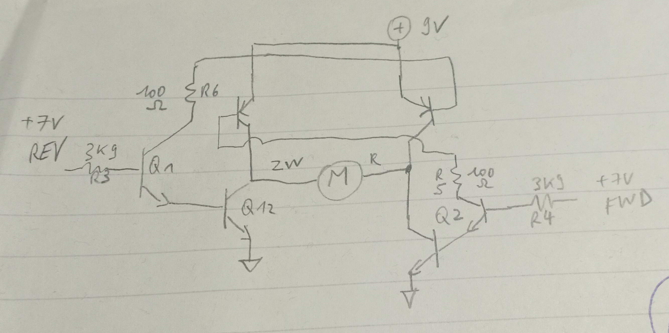 https://cdn.hackaday.io/images/1326281616615867621.jpg : original H-bridge
Improvement
We could try to reinvent the wheel and design an improved version of this discrete H-bridge. Instead we'll just use a tried and tested commercial one.
We could either use the Adafruit 3190 (single bridge) or the Sparkfun ROB-14450 (dual bridge). The latter being almost the same as the DFRobot DRI0044 (€3.72) or the Pololu TB6612FNG Dual Motor Driver Carrier. Let's use that DFRobot one, as it's the cheapest.
DFRobot DRI0044
So I ended up buying the cheapest option, which I may regret soon. The DFRobot board has only 12pins, while the Sparkfun board has 16 pins.
The DFRobot board saves pins by using only 1 pin to control the direction of the motor. The TB6612FNG motor driver uses two inputs per motor. This allows to brake the motor by bringing the two inputs too the same state. This is not possible on the DFRobot board. You can only break with the DFRobot module by going to reverse rotation.
Speed control
We have three parameters to play with:
Motor voltage
Set to 12V, that the maximum that the TB6612FNG can safely handle
PWM frequency
- Maximum 100kHz, limited by the TB6612FNG
- Don't choose it too high to limit eddy currents and switching losses
- Practical values : 5-20 kHz range
- Don't choose it too low to limit current ripple and hence torque ripple.
- Current ripple < 10%.
- According to the following formula, ripple is maximum at 50% duty cycle. The resistance in the circuit doesn't impact current ripple. So we can generate a square wave using a signal generator (50Ω output). Put it to 50% duty cycle and 12Vpp output and adjust pwm frequency until the current ripple drops below 10%.
- I built such a setup, but from a few kHz to 20kHz there was no noticeable difference in current ripple. The motor was not rotating.
ΔI =current ripple D=duty cycle [%], U=motor voltage, L= motor inductance, fpwm=pwm frequency
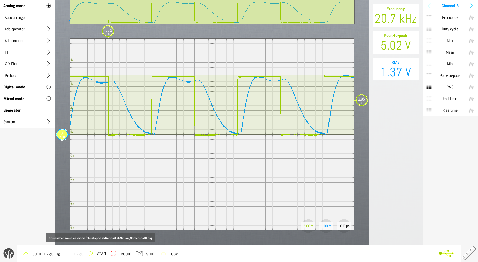
The frequency has been adjusted from a few kHz to 100kHz. At 10kHz to 25kHz, the current consumption by the motor driver seemed to be minimal. So let's take 20kHz as PWM frequency.
Duty cycle
Will be used for speed control, while the PWM frequency will remain fixed.
References
- Controlling Brushed DC Motors Using PWM – Optimal Frequency, Current Ripple, and Life Considerations
- Is there an ideal PWM frequency for DC brush motors?
PWM on the ESP32
Don't reinvent the wheel. Let's see if we can get "In-depth ESP32 PWM Tutorial | How to use PWM in ESP32?" to work.
Pin 14 is unsuitable as PWM-pin for the traction motor. At powerup this pin becomes high synchronously with 3V3 and remains high for 500ms. This causes the traction motor to spin.
Discussions
Become a Hackaday.io Member
Create an account to leave a comment. Already have an account? Log In.