 Kris Winer
There are a lot of moving parts to this project so I will describe the ingredients one at a time and then put them together at the end.
1) We have been working to exploit ST's new line of BLE-enabled STM32WB MCUs. We have developed a power- and memory-efficient Arduino core for several hardware designs including the Firefly development board and the Katydid wearable sensor board.
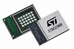
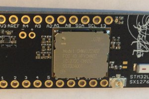
The STM32WB is a dual core MCU with a 32 MHz Cortex M0+ managing the BLE stack and a 64 MHz Cortex M4F for application programs. The STM32WB55 variant sports 1 MByte of flash memory and 256 kByte of SRAM and now is available as a 7.3 mm x 11 mm module for easier integration into embedded designs. The module also has 68 GPIOs available, making it perfect for designs that have a lot of serial peripherals.
2) We have been testing ST's new IIS3DWB ultra-wide-bandwidth, low-noise 3-axis digital vibration sensor (accelerometer). The SPI sensor has a bandwidth of 6.3 kHz at +/- 3dB, a data rate of 26.7 kHz, a noise figure as good as the LSM6DSM (75 ug/SQRT(Hz)) and uses just 1.1 mA running full blast. We have been testing this sensor using the Dragonfly development board which has a STM32L476 MCU with Cortex M4F running at 80 Mhz, so a close analog to the STM32WB55. We have been getting very good results so far in terms of data rate and FFT speed and accuracy. You can read more about our tests to date here.
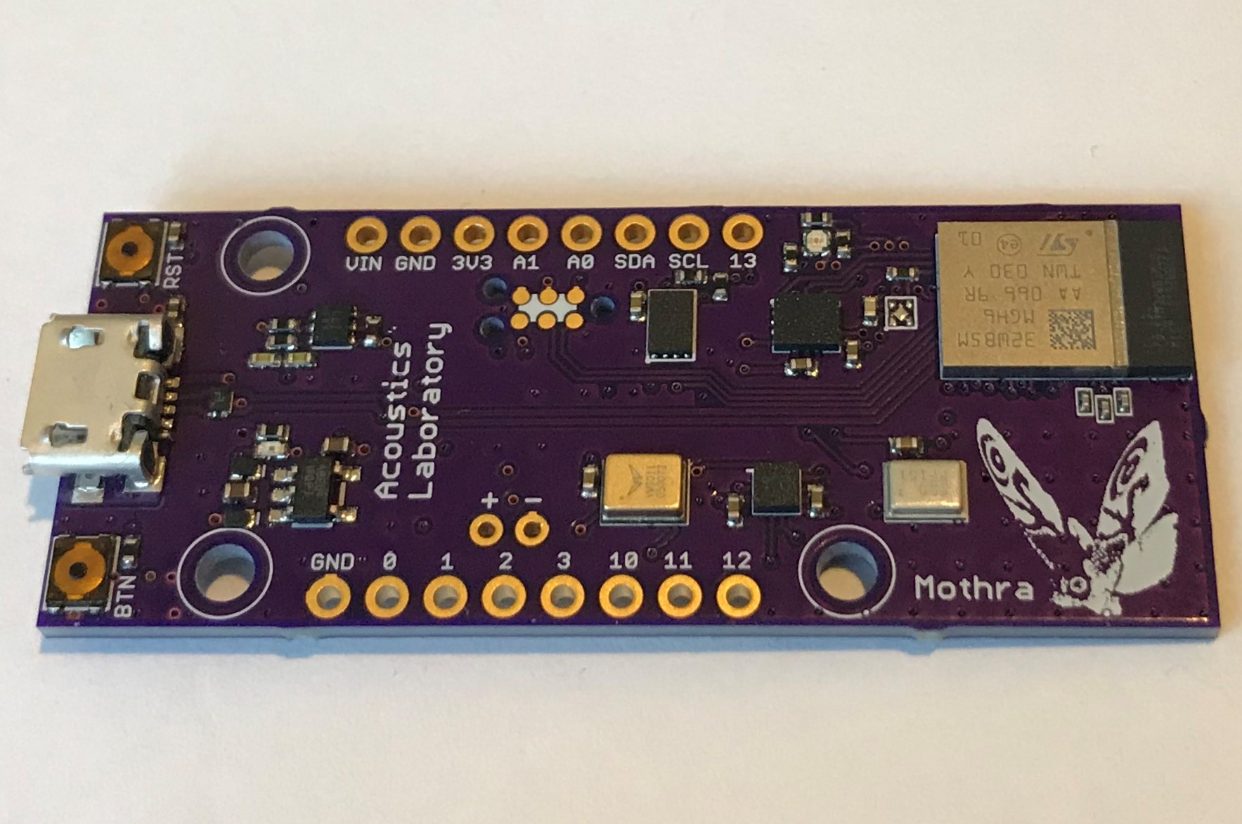
3) TDK (Invensense) has a line of PDM microphones that extend into the ultrasonic range. The ICS41350 measures sound from ~100 Hz up to 40 kHz. The ICS41352 from 100 Hz up to 85 kHz. The STM32WB55 has some hardware PDM filtering capability but for efficient analysis there is quite a bit of arcane and complex software filtering required to extract the best signal quality especially in the ultrasound ranges. We are selling breakout boards for these mics at Tindie and it is straightforward to record high-fidelity audio at 16 kHz and play it back via, say, Audacity using the Firefly development board. The challenge here is to extend this ease-of-use and fidelity to the ultrasound range.
4) Mothra is designed to be an ultra-low-power device. We have taken pains to choose components and strategies to keep power usage under strict control. For example, we are using a GPIO to power the ICS41350 to cut its otherwise ~12 uA sleep current to zero. We have an LDO controlling power to the NAND flash saving ~30 uA in sleep mode. This is a general feature of our designs and critical to any real application of the technology. In most cases, we expect derivatives of the Mothra device will be battery powered and remotely fielded with battery lifetime a key consideration. With this low power focus in mind, we have included Wake-on-Motion and Wake-on-Sound sensors on the board.
The BMA400 is a small, 12-bit, 3-axis accelerometer with an ultra-low-power mode using 800 nA running at 25 Hz and able to wake an MCU host via interrupt when motion is detected. In this mode, the interrupt engine is limited to simple threshold crossing on one, two, or all three axes with some configurable hysteresis. However, in normal mode, with access to more sophisticated built-in interrupt detection like step detect, tap and double-tap detect, orientation change detect, etc the BMA400 can still run at 12.5 or 25 Hz and use just 3 - 4 uA. The BMA400 can be used to detect vibrations and wake the system for fuller analysis and then detect a "no motion" condition allowing the system to go back to sleep.
The VM3011 is a new PDM microphone that embeds a wake-on-sound capability configurable by the user via I2C. The VM3011 remains in a low-power mode that uses ~10.5 uA and when the ambient noise background exceeds a user-defined threshold the microphone wakes in less than 200 us, sends an interrupt to the MCU host, and allows the system to wake to record and/or analyze the sound.
... Read more »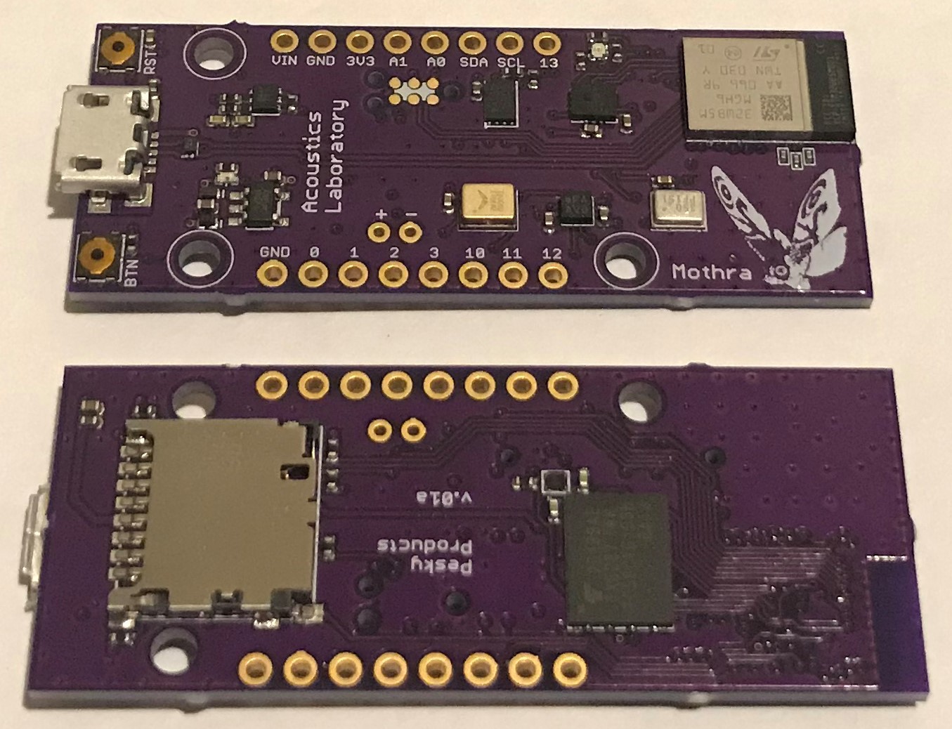


 Max.K
Max.K
 Maciej Jurczak
Ok, finally the arduino core is up there and running:
https://github.com/GrumpyOldPizza/ArduinoCore-stm32wb
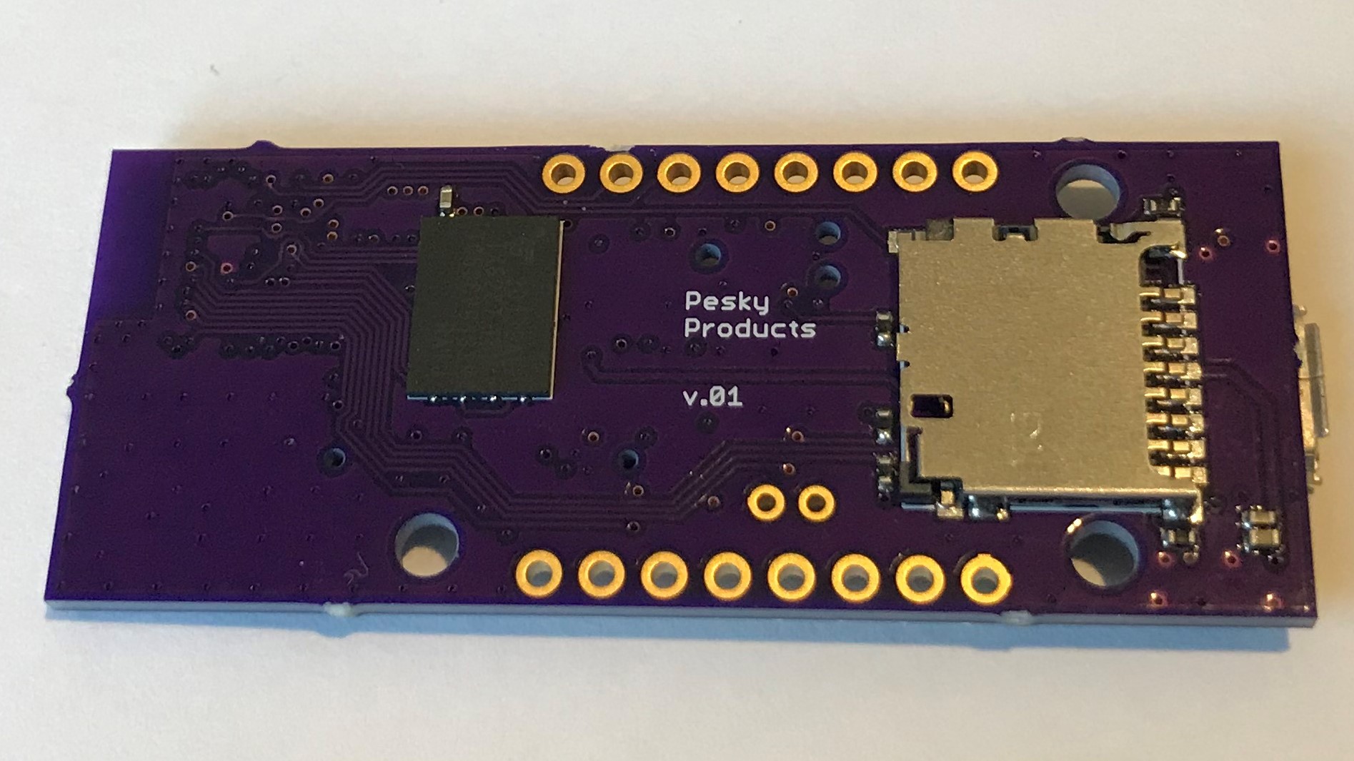
NAND flash is not working ... of course. Something always goes south. Have not gotten the SDCARD detect pin to work properly either, so this is disabled for now (i.e. it always tries to read the card).
A couple of things ... because I am ticked off that SD_DETECT does not work ... so as therapy a few lines ...
This board is kind of a tad out there. It has 10 usable GPIOs. On there LPUART, which can in theory go up to 921600 baud. Full RTS/CTS support. For inquisitive minds, yes there is XON/XOFF as well. There is a master/slave I2C port, and a SPI port. So nothing special ... except that, yes the SDCARD is on it's own SPI. And yup all the internal sensors are on their own I2C bus, so that they are shielded from any screwups on the header pins.
The interesting part starts now with IIS3DWB. Everybody who looked at the STM32WB datasheet knows that this part has only 2 SPI ports, which are already spoken for. So what Mothra does is to put IIS3DWB onto USART1 and abuses it as SPI port. 8MHz CLK, full async DMA supported. That means a bandwidth of about 800kB/sec. IIS3DWB needs about 190kB/sec. So that was a tad involved to do. Net result is that it's possible to read IIS3DWB while being able to read/write to the SDCARD at full speed.