 Patrick Van Oosterwijck
With the pack built, it was time to test. The first thing I noticed was that the pack had no output voltage. This is normal because while building it, you can't really attach both cells at the same time, so the protection chip decides that one of the cells is low/missing and turns the output off. The condition is cleared by providing some charge current to the pack. At that point I saw 6.6V on the JST VH connector.
Time to put the pack on my electronic load and put some load on it. The pack was designed for 4A max output. Let's start with a 2A load:
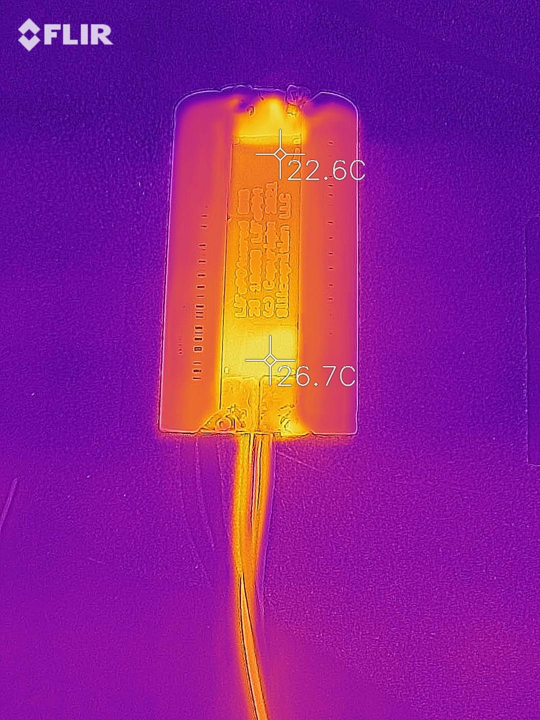
The thermal image shows a minor 4 °C temperature increase at the current sense resistor and dual MOSFET that disconnects the pack if there are issues. My calculations indicate that at this current level, the power parts would dissipate about 0.17W.
Let's crank it up to 4A load:
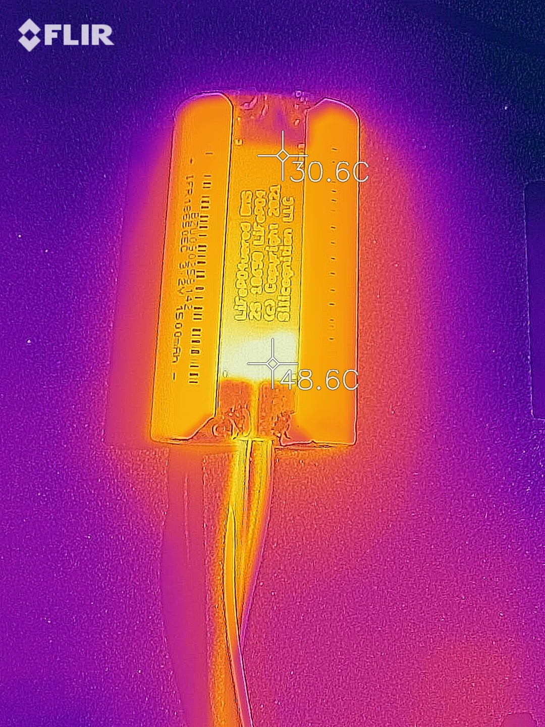
As expected, more heat at this load. But very reasonable! My calculations indicate that at this current level, the power parts dissipate about 0.7W. There's enough power dissipated that the pack warms up a bit, so comparing to the previous baseline, the temperature increase is about 26 °C. This is at ~24W output power!
There has to be some voltage drop across the current sense resistor and protection MOSFETs, resulting in some losses, because the pack protection chip uses this voltage drop to protect against over current and short circuit. The over current detection threshold is at 0.2V.
Since there are tolerances on the detection voltage, the current sense resistor and especially the RdsON of the MOSFETs, the component selection was done to end up with a over current detection range of 4A - 5A. The goal is for the threshold to be above the maximum advertised current (4A) and the maximum current supported by the cells (5A). My prototype pack had protection kick in at 4.6A.
I let the pack run down to empty to check the under voltage cutoff. I had specifically made the pack with some cells that I had abused before to have some differences between the cells. If one cell has less capacity than the other, it's easier to observe that the protections work correctly. In this case, one cell reached 2.0V while the other one was still at 2.7V, and the pack correctly disconnected. Success!
At that point I started to charge the pack with my bench power supply at 7.2V with a current limit at 1.5A. Both cells quickly recovered to 3.4V. Near the end of charge, when voltage starts to increase again, I reduced the current limit to 0.2A because that's the level for which the balancing circuit is designed. Why only 0.2A? Because we are using passive balancing, we just burn off excess power to prevent one of the cells from being overcharged if the other isn't full yet. Because this may happen for instance in a outdoor box out in the sun in Arizona in summer, we don't want too much power to be dissipated for fear we get the cells too hot. With the current component values we dissipate 0.72W when balancing a cell.
Here is a thermal shot when one cell is full and passive balancing for it kicks in:
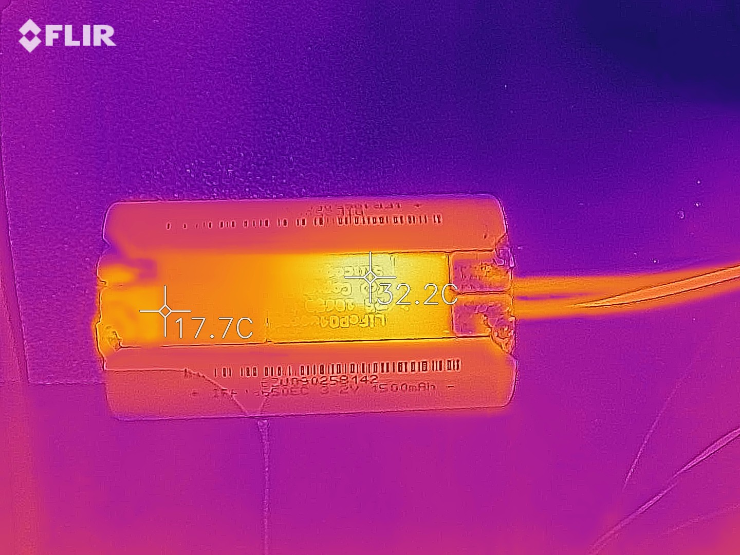
The temperature increases by 14.5 °C where the balancing resistor is located.
In this picture both balancers have kicked in:
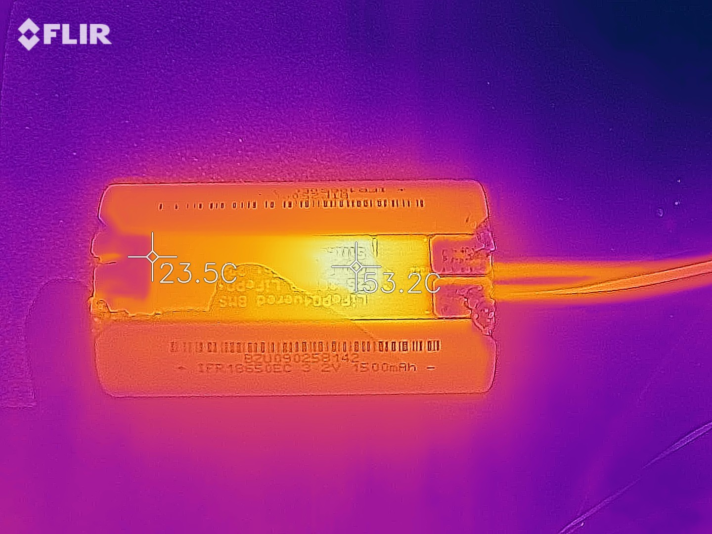
This increases the board temperature by about 35 °C. Of course, having both balancers on is not really a mode that's normal if you're using a real charging chip. Both cells are full at this point and the charger is supposed to turn off. But my bench supply of course happily will keep sending 0.2A through the balancing resistors. :)
All basic pack protection functionality seems to work as expected! Very happy with the progress.
Discussions
Become a Hackaday.io Member
Create an account to leave a comment. Already have an account? Log In.