 agp.cooper
Reducing the Serial Baud Rate
The 115200 baud for the 7.3728MHz version of the machine is just too fast.
The serial clocks can be reduced by a factor of six for a 19200 baud serial rate.
Here is a schematic for a modulo 6 design that I have added to the design using 74HC74 D-Latches:
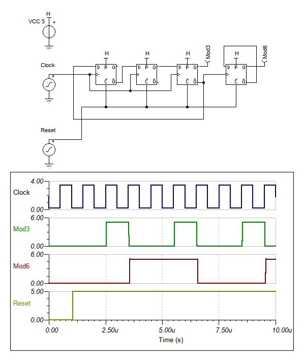
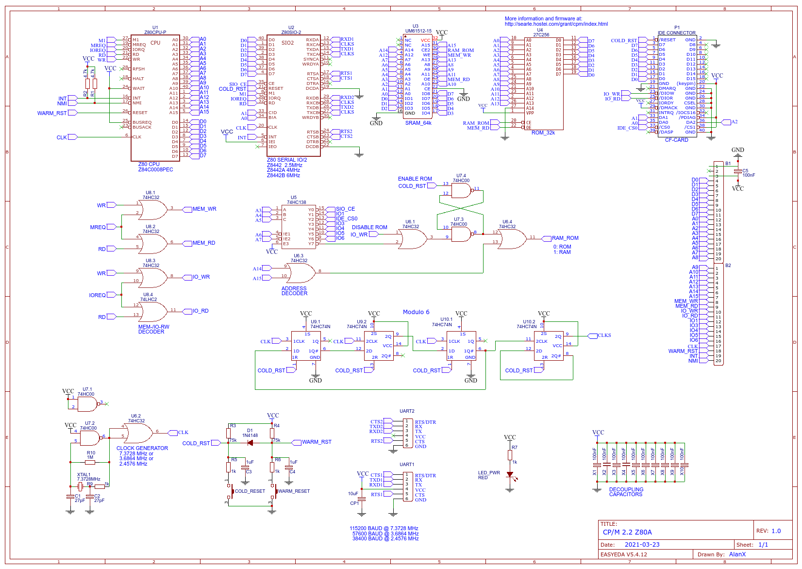
Here is an updated schematic:
Flash Drive Support
The next thing I want to do is add Flash Drive support for the W29C020 (256k x 8bit).
Updated the PCB for 19200 Baud Serial with a 7.3728 MHz Clock
Updated the Schematic and the PCB. It is sort of worth while building this version.
Adding the Flash Drive requires a bit of coding.
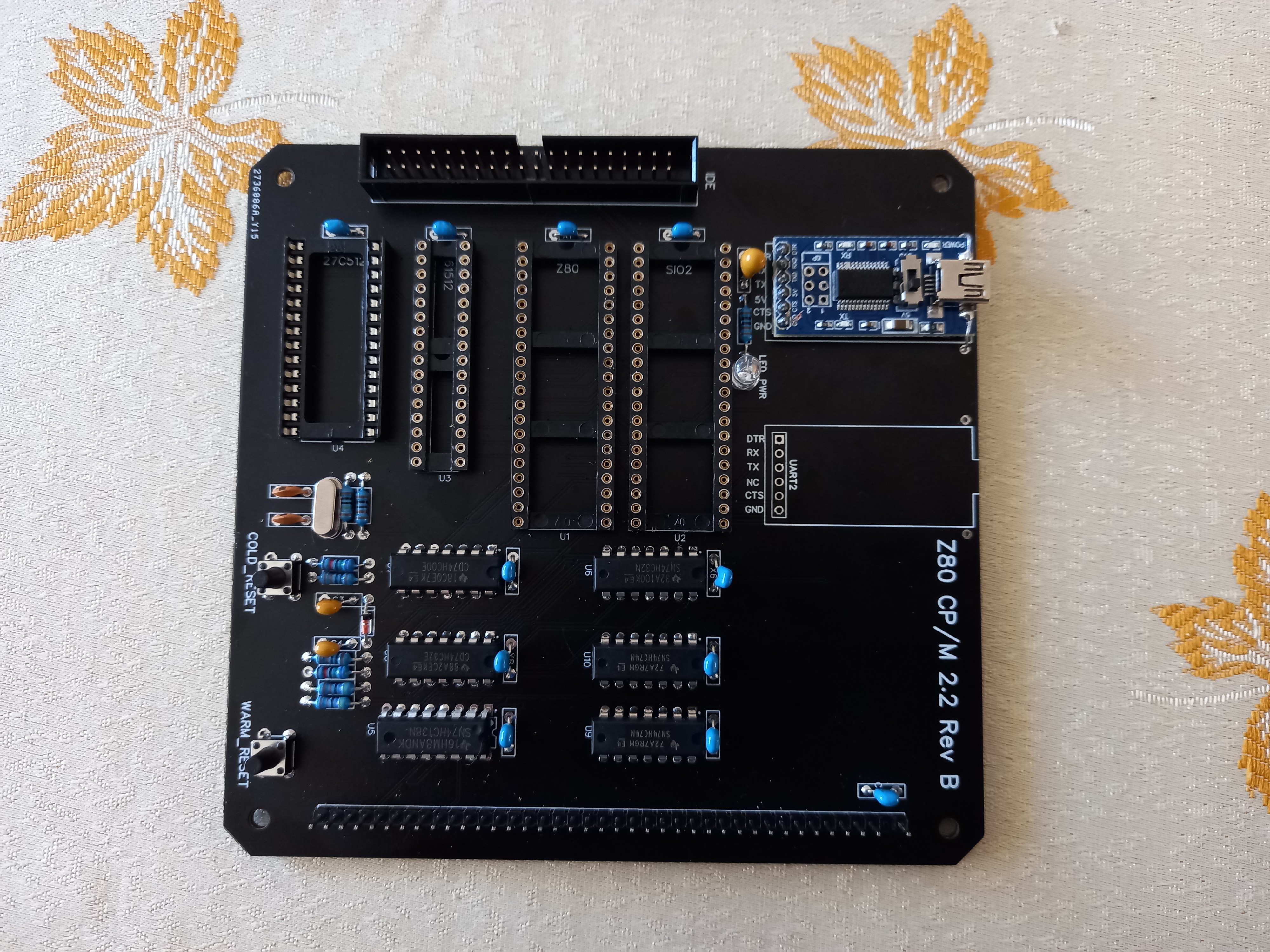
Updated PCB has Arrived
The update PCB has arrived:
Unfortunately there were two problems:
- The main clock is running but is pulled down(?)after the buffer.
- The reset circuit is dulled down.
Pulled the Z80 CPU, no change.
Pulled the Z80 SIO/2 and now the main clock and reset works.
Checking the modulo 6 circuit and it is locked up?
Check the Z80 CPU in the original board and it works.
The Z80 SIO/2 is dead. The fact that it pulled down the clock and the reset lines suggest it may be a fake chip.
Checking the modulo circuit it did work once. I think the reset rise time is too slow for the relatively fast clock. Very small differences between the two chips results in the different reset times thus locking up the circuit. I will need to redesign the reset circuit.
Minor Success
A minor success. I removed the de-bounce capacitors from the board and the modulo 6 clock divider now works. I can configure a divide by six without the reset signal by using the spare NAND gate but better to have a proper reset signals.
However the serial is still dead. The SIO/2 works with the original board if I swap it out so I must have a miss understood something about dividing down the serial clocks or there is a wiring error. I just can't find the problem.
Swapped the ROMs between boards and they are okay.
I was a bit rough re-soldering the connection pins for the USB-Serial board, may be I broke a track? No.
Okay, must be a schematic/wiring error. Yes, found it, the RAM CE is inverted. No my mistake.
New Boars Arrive
New boards ordered (with my RAM CE mistake). Assembled. Hacked the RAM CE. Clock and Modulo 6 work fine. Okay pull the modulo 6 chips and jump the serial clock. Checked the reset circuit. Back to where I was a week ago.
Spent the next day checking the schematic, no success.
Measure the signals on the old working board and compared them to the dead board.
Something wrong with IOREQ, it looks tri-state?
Isolate the problem to the Z80 CPU. Did not expect that!
Swapped it out and still not success.
Something wrong with the D0-D7, the appear pulled down but not all the time.
Starts okay and then goes down.
The only chip I have not pulled is the RAM. Something for tomorrow.
Tomorrow is Here
Swapped out the PROM and the SRAM. Same problem. Pulled the SIO/2 and yes.
I bought three of these SIO/2 and Z80 CPU from the same place. They are used chips (not new old stock). At least one dead Z80 CPU and SIO/2. One SIO/2 had broken pins. Not a good buy!
Swapped my last unused SIO/2 chip, same problem. Checked the supply voltage and that is still good. I check the good board and I have a mix of signal (i.e. 0v and 5v) and some "tri-state" (i.e. 3.4v). The databus on the Z80 does go tri-state normally so that is okay, but 3.4v tri-state seems odd on a all CMOS system.
Tri-State?
Okay, I will add a 22k pull up resistor to see it it really is "tri-state". At first it seems to be yes until I hit the reset. It seems as if I have exceeded the power supply limits from the FTDI (i.e. USB to serial converter).
Perhaps Z80 CPU is not booting up correctly. With the power supply circuit I am using a cheap no-name 10uF tantalum while on the working board I use a 22uF tantalum from my local electronics store.
There is a problem with the working board with some of the SIO/2 chips. The board will reboot a few times before stabilising. This happened with the used version of the chips.
Which is why I focused so much on these chips. But now I have a new line of exploration to follow. The (static) power supply is not up to task:
- Z80C CPU 50mA
- Z80C SIO/2 100mA
- AT29C256 50mA
- UM61512 160mA
- Total 360mA
So what does a USB 2.0 connection deliver?
Minimum (standard) 100mA and maximum (high power) 500mA!
So it should be okay but no guarantee.
I will try upgrading to power supply capacitor next. At least after our 3 day lock-down!
Updated the powers supply, still no success. This is getting very frustrating!
I will swap main components with the working board and see if this is the problem.
I can't swap out the USB to serial adapter but I really doubt the problem is here as I have tried this before.
At least I can then confirm that the main components are okay.
Then I will check the nets versus the PCB board (EasyEDA changes components from time to time so it is possible a net is missing without showing an error).
After that, I have no choice but to return to the working board design and start again.
Tracing the PCB
Okay, this morning I grabbed a spare PCB, my multi-meter, logged on to EasyEDA, printed out the schematic, and started tracing the nets on my PCB.
The first net "A0" checked out. This is going to take some time!
Jumped to "D0" and as I gazed at the schematic I saw that I had swapped D0-7 with D7-0. Bugger!
Checking the working board schematic, it was right. So I had introduced this error.
I have wasted two months over this error! But this is what happens when you get older, you just can see the bugs. Oh well.
Updated the latest board and sent if off for manufacture.
Very Annoyed with Myself
I got the updated board, installed all the components and fail!
Checked everything I could and I suspect the PROM.
It is working but the code is wrong. I just know!
I checked the schematic over and over again but I cannot see it.
Very frustrated.
I wandered over to the PCB and checked import.
Shit, I forgot to import changes before rebuilding the PCB and sending it off for fabrication.
What a waste of components.
Oh well, update the PCB and send it off again.
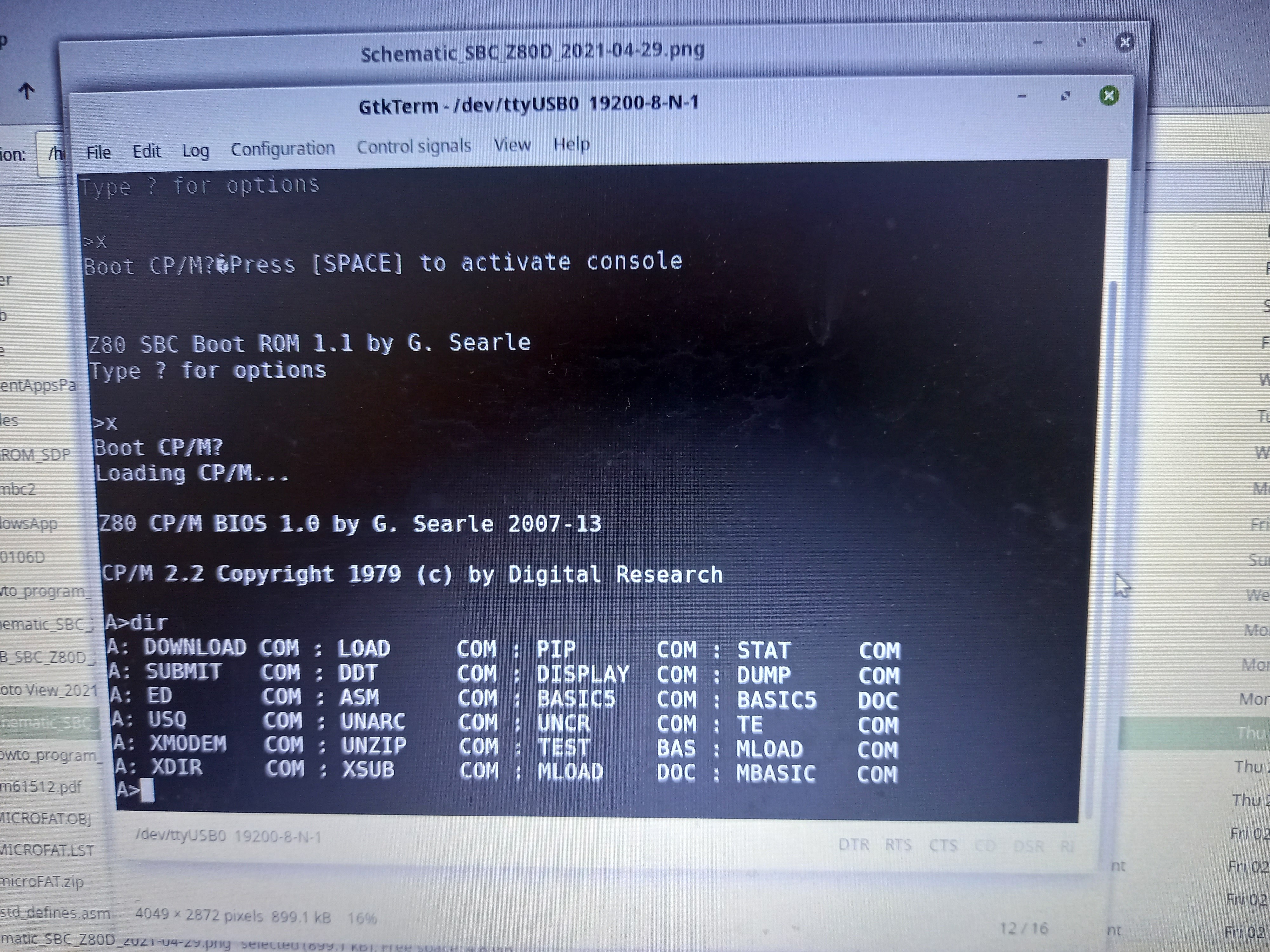
Finally it Works
Finally it works:
And it looks nice in white:
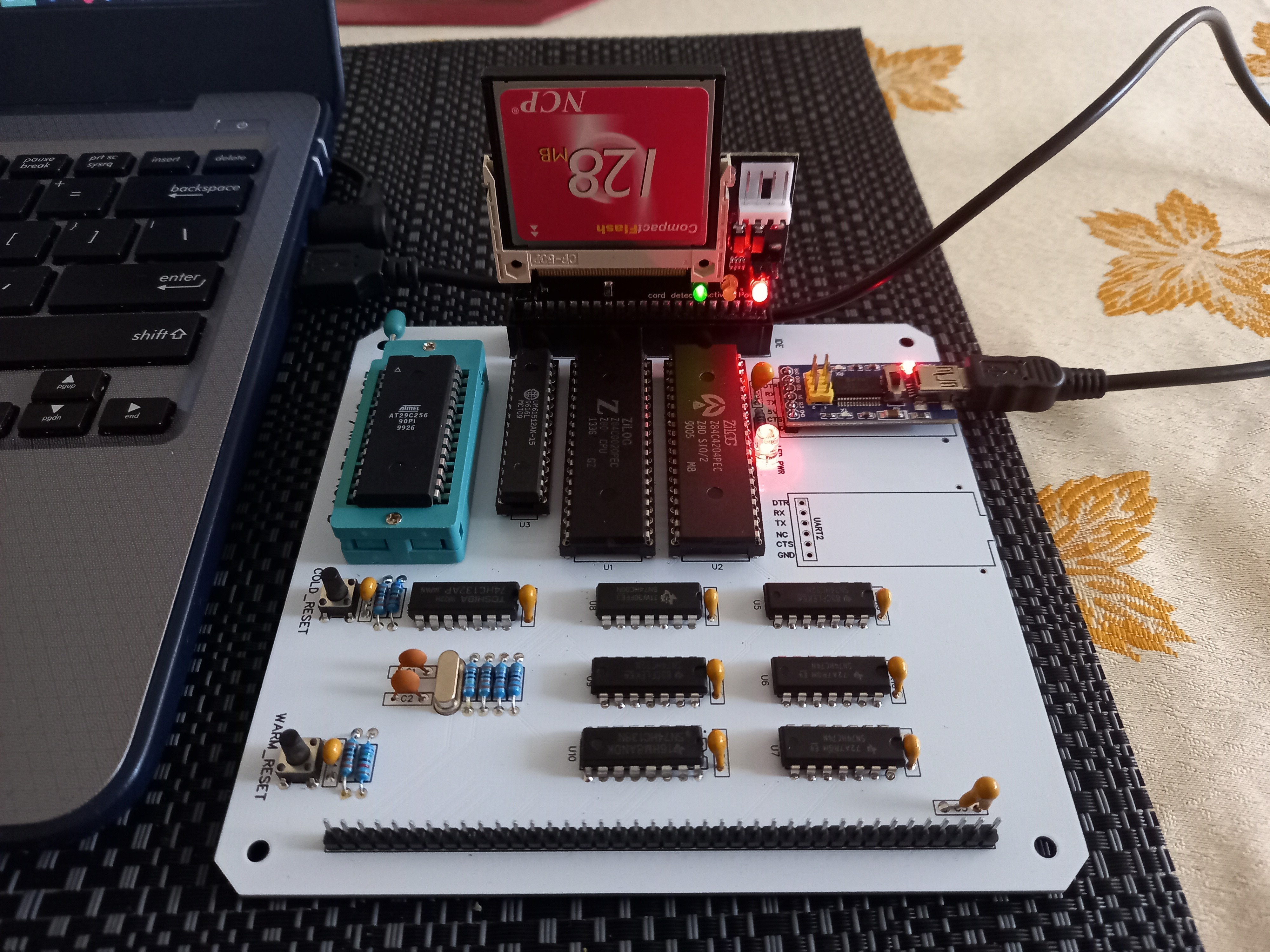
The SIO/2 is overclocked but working fine.
AlanX
Discussions
Become a Hackaday.io Member
Create an account to leave a comment. Already have an account? Log In.
Okay, my last post is still a draft. I ran into assembler coding problems (for the next version) and spat the dummy. If you go to https://easyeda.com/temporary you will find my project area.
There are two versions available to the public:
SBC Z80D: https://easyeda.com/temporary/sbc_z80d
SBC Z80E: https://easyeda.com/temporary/sbc_z80d_copy
SBC Z80D is the version I have built.
SBC Z80D is a version for jumpers for all the version of the Z80SIO, that is Z80SIO-0, Z80SIO-1 and Z80SIO-2.
You can find the PCB designs there as well. You can either get them make through EasyEDA and JLCPCB, or you can download the gerber and get the PCB made somewhere else. It costs about $40-$50 for 5 PCBs delivered.
I can post one of my spare PCBs and a programmed AT29C256 for free if you like.
Otherwise you will have to build your own programmer.
Regards AlanX
Are you sure? yes | no
The problem was the reset signal rather than the modulo 6 design.
If the clock rises too slowly, differences in the CLR trip point matter.
Let me check if the schematic is upto date.
AlanX
Are you sure? yes | no
Sorry, the new schematics?
the version of the schematic is the one you declare not working, also that of the pcb, update schematics and pcb please, thanks for the work you have done
Are you sure? yes | no