 Wissam Tedros
let's talk about this circuit, as I think it is one of the most important features on my board.
Anyone who made a robot and chose standard RC servos as actuators, might already understand why this circuit it present, especially with 12 quite powerful servos.
Ever pressed the reset button on your microcontroller and all the servos started acting crazy and brutally moving left and right? the answer is probably yes, and that is due to the servo signal pin picking up some random signals while the microcontroller is in reset mode and all the GPIOs are floating.
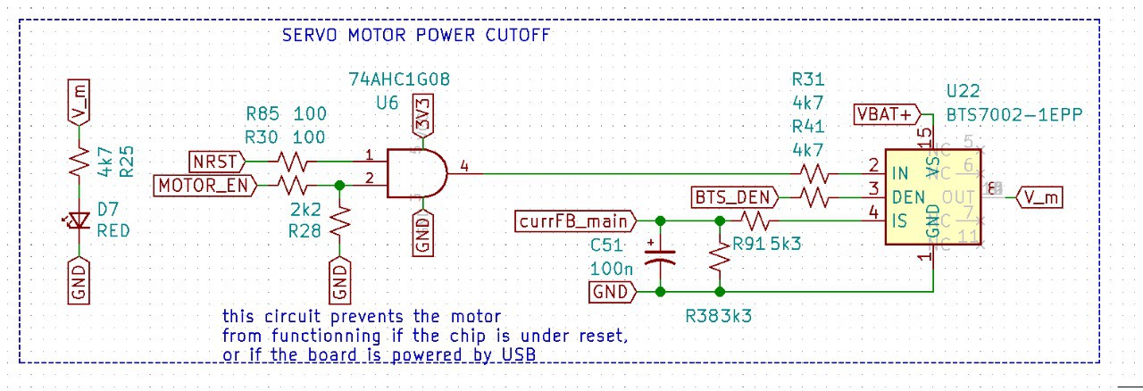
This circuit Prevents that, how? simple, an IC called load switch, that acts like a mechanical switch but except it closed or open based on the input state of its Vin pin, only when Vin is HIGH, the switch is closed, and V_m = VBAT+
now when is Vin HIGH? when the NRST and MOTOR_EN(GPIO OUTPUT pin) are both high, NRST is the reset state of the microcontroller, for the STM32f4, when NRST is HIGH, then the chip is in "run" mode, when pulled LOW, the chip is in reset mode.
So, only when the microcontroller is running, AND the GPIO output is set HIGH, then the servos receive power, when the chip is in reset mode, say you want to flash by SWD, or just press the reset button, all power to the servos is cut, and no matter what the signal pin of the servos pick up during reset, they won't move to unpredictable positions.
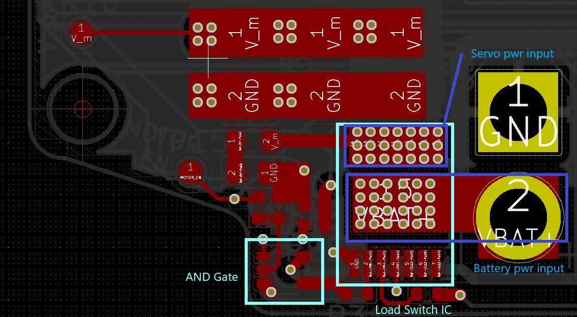
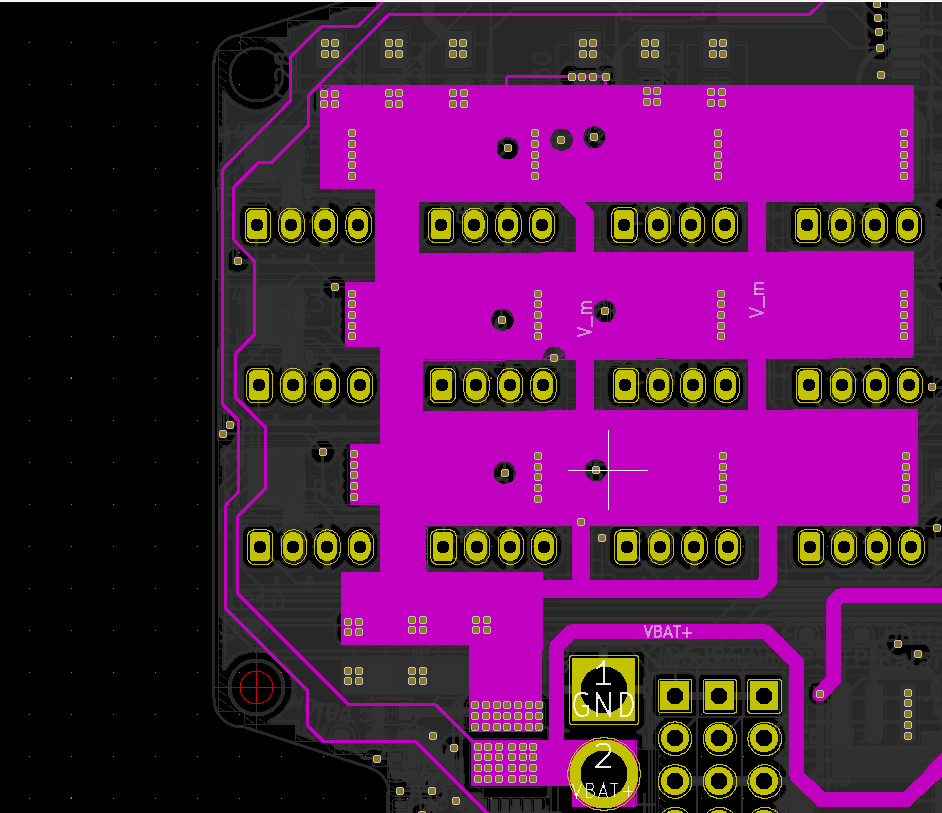
Here is a closer look at the PCB layout of that circuit, since its location is on the edge of the board, I decided to use all 4 copper layers from the battery connector to the load switch, this particular switch is good for a lot more current than the robot ever draws, after hours of usage it barely gets warm, the circuit works like a charm, of course there's is an indicator LED to confirm that the output voltage is present.
the above schematic also points out that the switch will not be closed if the board is powered under USB, this is done by software (I should have pointed this out), this is just for safety reasons, when the batteries are charging or when flashing by DFU.
Discussions
Become a Hackaday.io Member
Create an account to leave a comment. Already have an account? Log In.