 xD
xDBackground
Robinhood is an anti-capitalist, community-based project that currently runs two grocery stores in Berlin. Instead of accumulating capital, as regular businesses do, the stores donate 100% of their profits to fight extreme poverty and climate change.
Employees and volunteers are always present in the store to explain the Robinhood concept to newcomers. In addition, the founders had the idea of putting an old rotary dial phone in front of the store, where people can sit down, compose a number, and hear a short recorded presentation of what Robinhood is about. Depending on the number, the explanation is given by different people and/or in different languages. This project details how the rotary phone was modified to achieve that goal.
This blog post was very helpful during the project.
System design
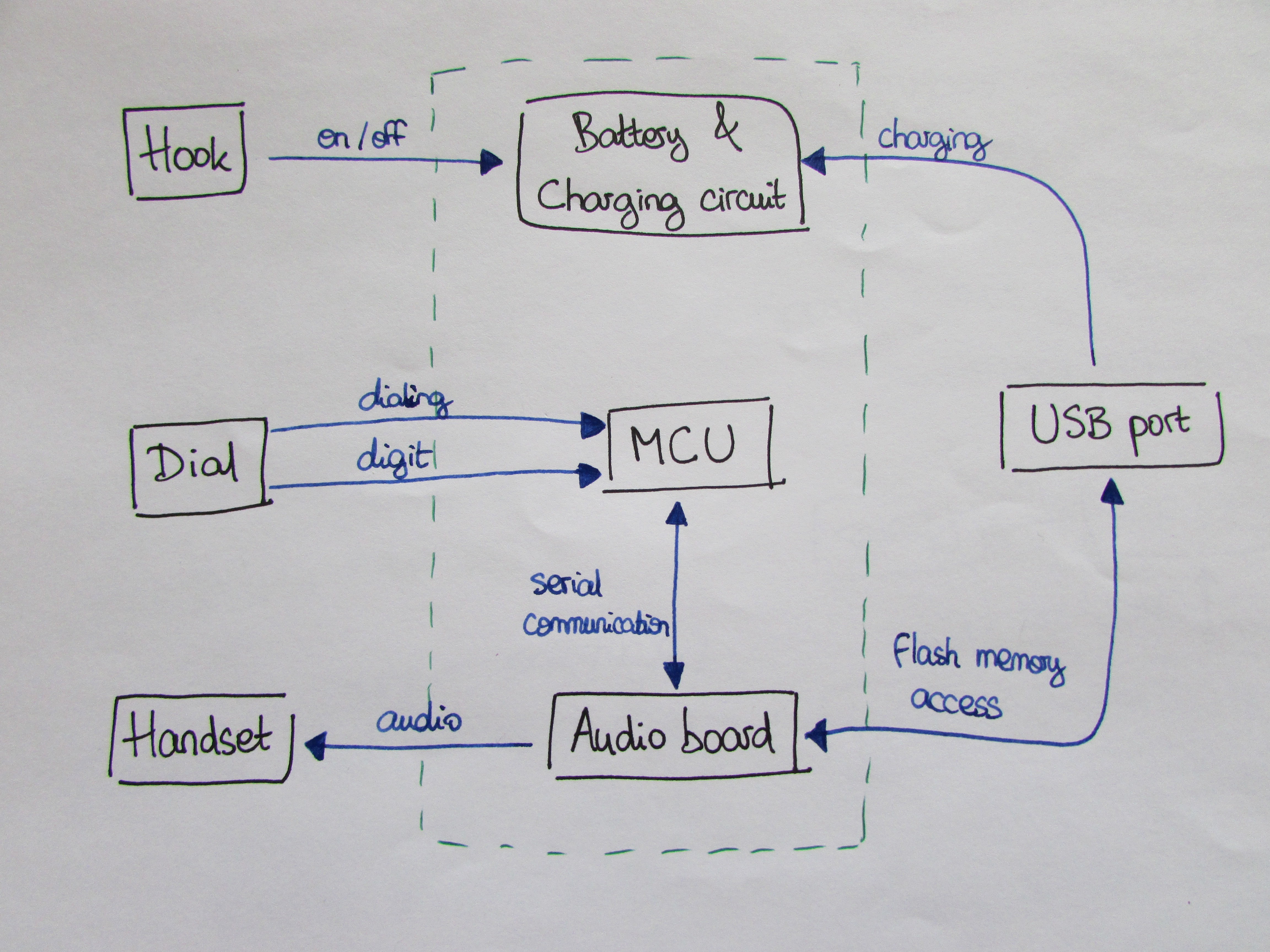
On the diagram above, the original phone components are on the left, and the green dashed line symbolizes what is enclosed in the phone case.
- The core of the system is a microcontroller. It receives signals from the rotary dial, and communicates with an audio board via its serial port.
- The audio board is connected to the phone's handset and plays audio files according to the MCU's requests.
- The whole system is powered by a battery connected to a charging circuit. The power is switched on by taking the handset off the hook, and off by hanging up.
- Both charging the battery and storing audio files is done via USB port.
Phone circuits
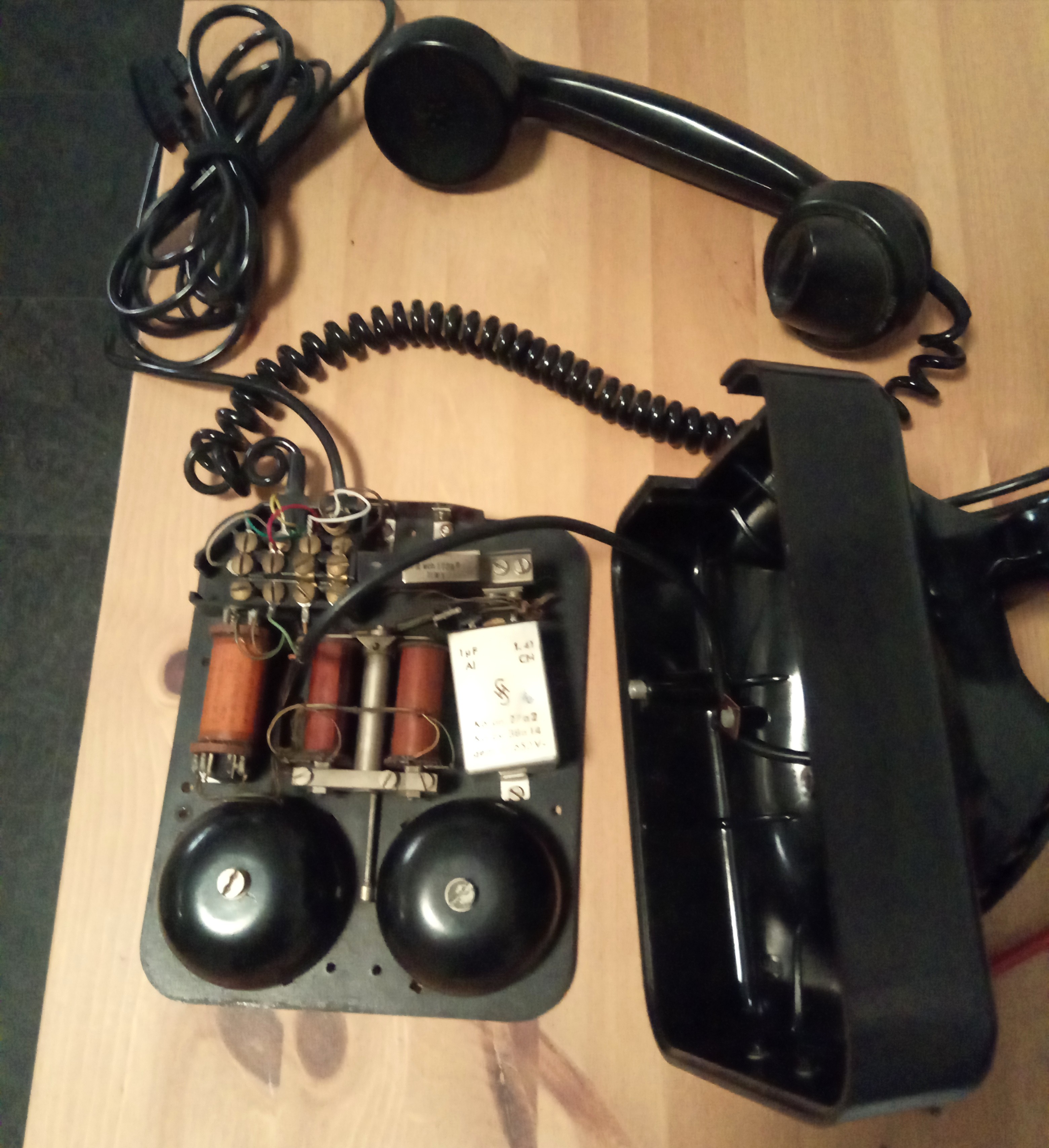
The phone's original electronics are quite straightforward. Several parts aren't useful for this project (specifically the phone line and the ringing circuitry in the lower part of the case), so I'm not going to describe them.
- The handset has four wires: two for the speaker, and two for the microphone.
- The dial provides two signals: the first indicates that a dialing operation has started, and the other encodes the dialed digit.
- The hook switch, the handset, the line cable, and the ringing circuitry are all connected to the terminals in the top-left part of the case.
- The hook pushes down on a sort of spring in the top-right part of the case that provides two switches: one normally open, and one normally closed.
Hardware
Components
The hardware selection is the following:
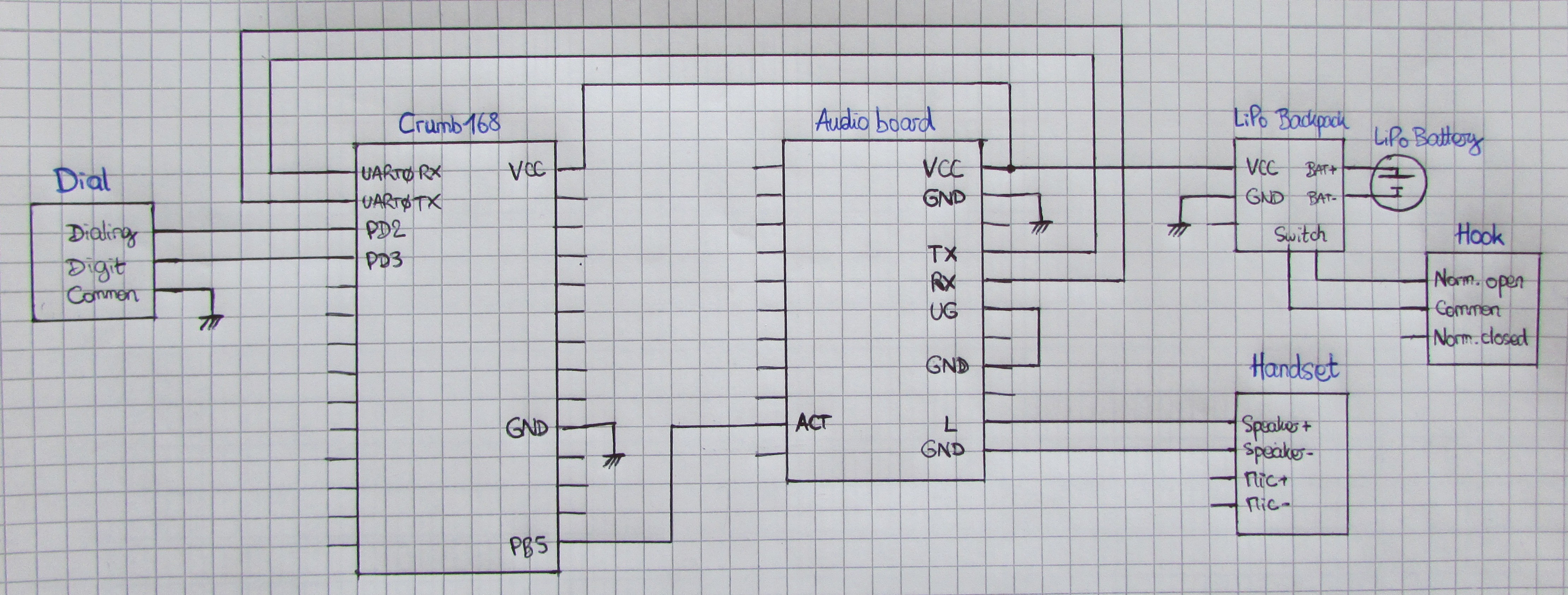
- MCU: ATMega168PA, for the simple reason that I had one available on a Crumb168 development module.
- Audio board: Adafruit Audio FX Mini Sound Board with 16 MB integrated Flash memory. The board supports WAV and OGG files, has a micro USB port, a stereo line out that can drive the phone's handset, and can be controlled by pin triggers or by serial commands. As the blog post cited above mentioned, this is a great little board.
- Battery and charging circuit: 2000 mAh LiPo battery, which should be sufficient to use the phone for a while, and an Adafruit LiPo backpack which can be mounted directly on the audio board, thus making the development even easier.
Schematic
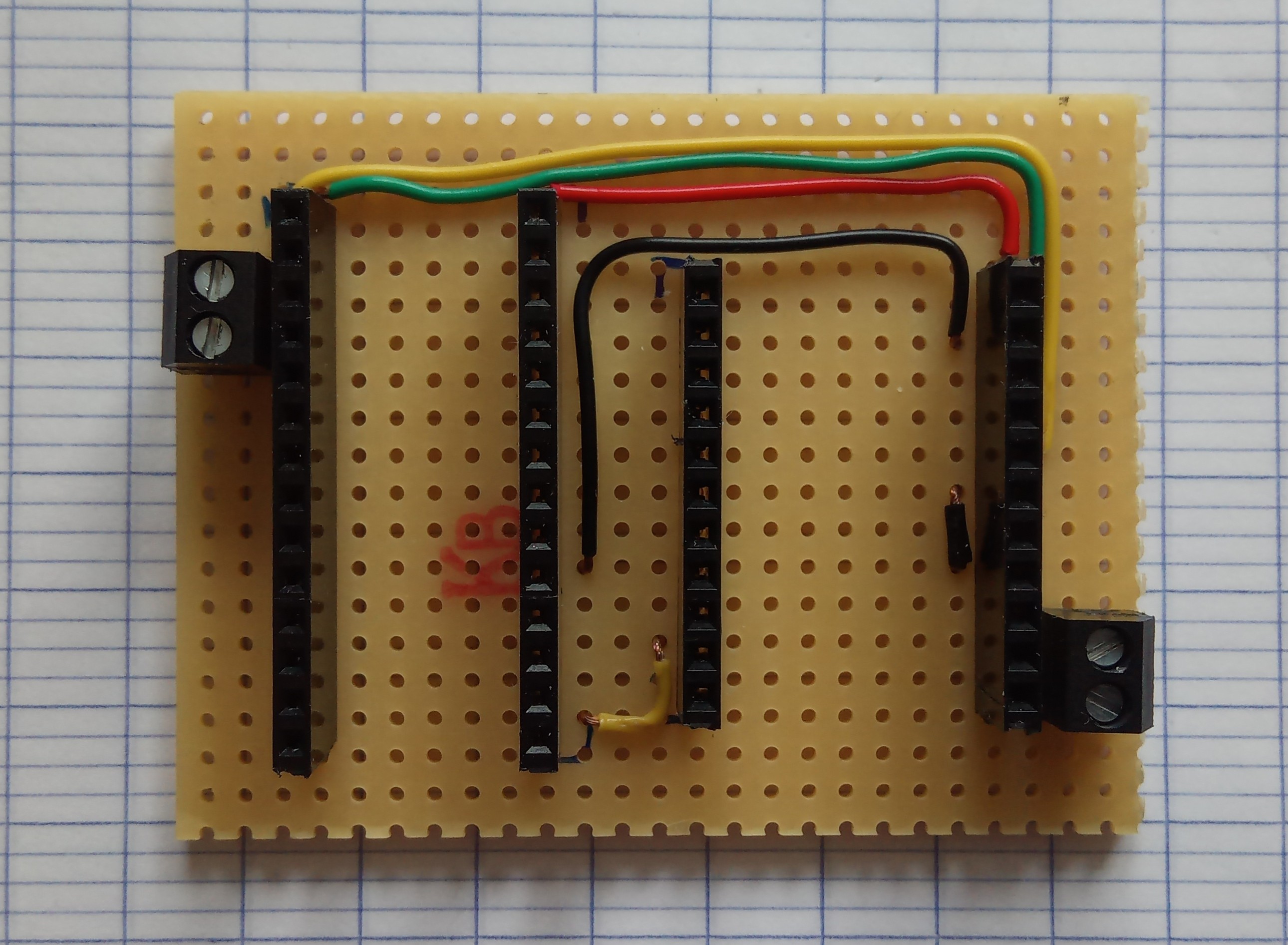
Wired perfboard![]()
Assembled phone![]()
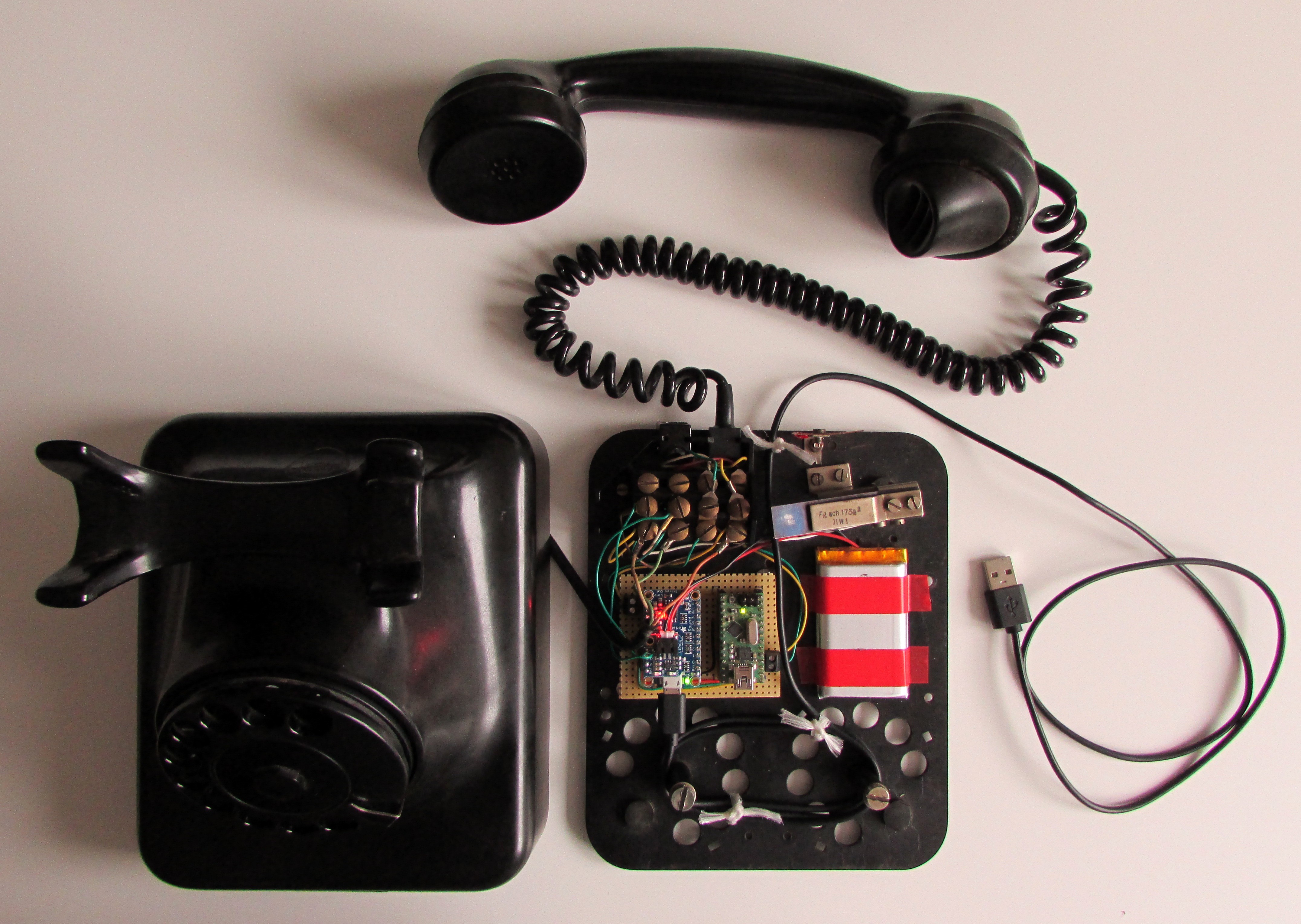
The perfboard with Crumb168 and audio board (upside down compared to the perfboard picture above), plus the LiPo battery, fit where the ringing circuit and the bells used to be. I set up a USB cable connected to the audio board and coming out of the back of the phone case. Placing the board's USB port near one of the phone's preexisting openings wasn't possible, and I didn't want to cut a new opening somewhere for fear of damaging the case.
Software
The software is available on GitHub. I tried to match the phone's behavior to what an uninformed user could expect: you pick up the phone, hear a dial tone, dial a number, listen to what your interlocutor says, they hang up, you hear a busy tone, you hang up. There are a few timers here and there, for example to wait a few seconds between the other side hanging up (i.e. the audio file ending) and playing the busy tone, because it makes for a less abrupt experience.
Decoding dialed digits
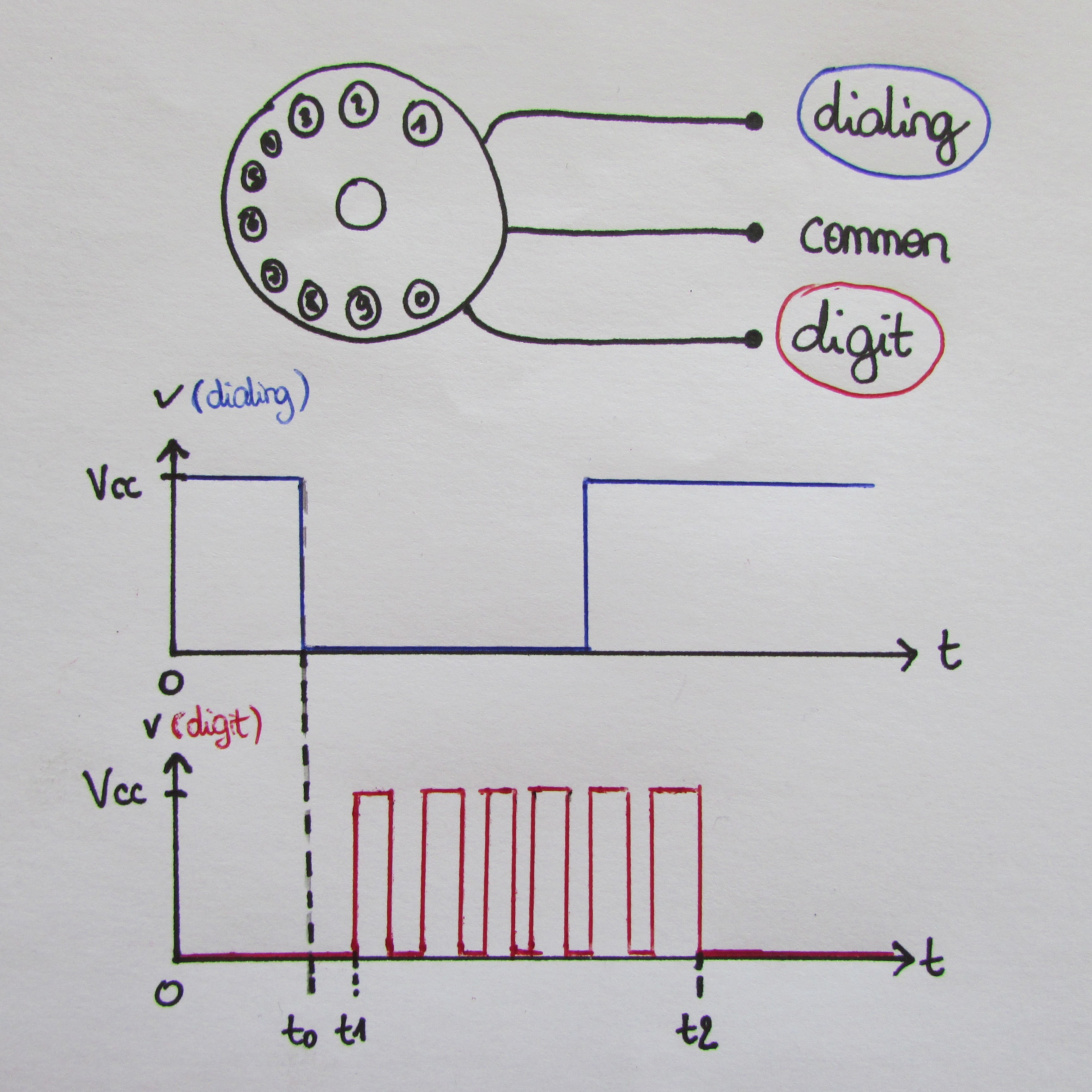
Possibly the only non-trivial part when developing the software was decoding the dialed digits. As mentioned earlier, the dial provides a signal indicating that dialing has started, and the other encodes the dialed digit. Both signals are referenced to the common wire. In this project, "common" is tied to ground, and the two signal wires are connected to two separate MCU pins configured with pull-up resistors. This gives the graphs pictured above.
There is a normally open switch between the dialing wire and the common wire. The switch closes when the user turns the dial clockwise (i.e. starts dialing a digit, t0 on the graph). It opens again some time after the dial is released. On this phone model, the switch opens again before the dialing is finished (i.e. before the dial has gone back to its original position).
Conversely, there is a normally closed switch between the digit wire and the common wire. While the dial turns back to its original position (between t1 and t2), the switch opens once for each digit increment. For example, the graph above shows that the signal has 6 edges (rising or falling, it doesn't matter) while the wheel is turning back, which encodes the digit 6.
The software only starts monitoring the dial signals while the dial tone is playing. First, the signals are debounced with an algorithm based on this post by Jack Ganssle. I found experimentally that the signals can be considered stable if they kept the same level for at least 5 samples at a sampling period of 5 ms.
When a falling edge occurs on the debounced "dialing" signal, the program starts counting the edges of the "digit" signal. Every time a digit is successfully decoded, it is stored as part of the dialed number. The software keeps monitoring the dial signals as long as any edge has happened not too long ago (in the current version, 3 seconds). Once that delay has passed without any activity, an internal state indicates that a complete number is ready to use.
Communication between MCU and audio board
Adafruit's audio board can be controlled by serial communication, as explained in the tutorial. I used AVR-UART-lib to set up the MCU's UART0. The software provides a function to play an OGG file stored on the audio board's flash memory by name. Together with the number decoding described above, this enables matching a number to an audio file. For example, if the number "157" is dialed by the user, the MCU asks the audio board to play the file "157.OGG". If the file doesn't exist, the software makes the audio board play the busy tone.
Limitations
- The phone can't ring, since I removed that part of the original circuit.
- It takes about a second for the audio board to boot up, so the dial tone isn't heard instantly when picking up the handset.
- Tapping on the hook to reset the call (as you would do on a real phone) sometimes doesn't work, because the circuit needs a little time to power off and to power back on.
- After the busy tone has played for a while, the system could go in power save mode (as was done there) instead of just staying idle. This would save battery in case the user doesn't hang up properly. But since the MCU board is powered by the audio board, and not the other way around, I didn't find a solution for that within the project's time constraints.
- I'm not sure how sturdy the phone is. I glued, taped, and screwed everything I could inside the case, so I hope it will withstand some abuse.
Summary
The phone is used intuitively like a real phone. New audio files linked to an arbitrary number can be stored on the audio board's Flash memory via the USB cable at the back, without having to change anything to the software.
It was a fun little project, and I heard that people visiting the store enjoyed using the phone. Working with ye olde electronics like this is pretty cool, because all the components are easy to understand, and you can see that everything is assembled by hand. Plus, the feeling of using a rotary dial is very satisfying :)