Close
0%
0%

Roomba RPi

iRobot Roomba 690 enhanced with a Raspberry Pi Zero 2W and IMU.

Similar projects worth following

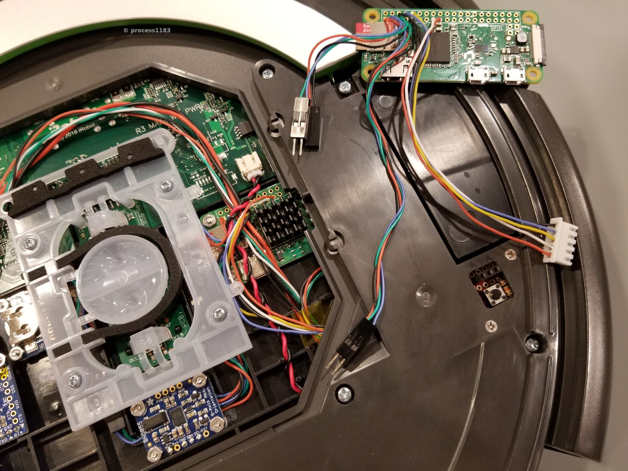
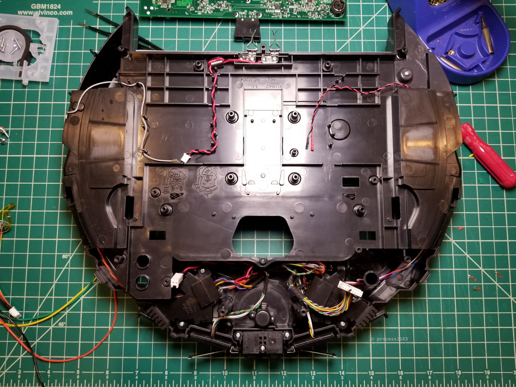
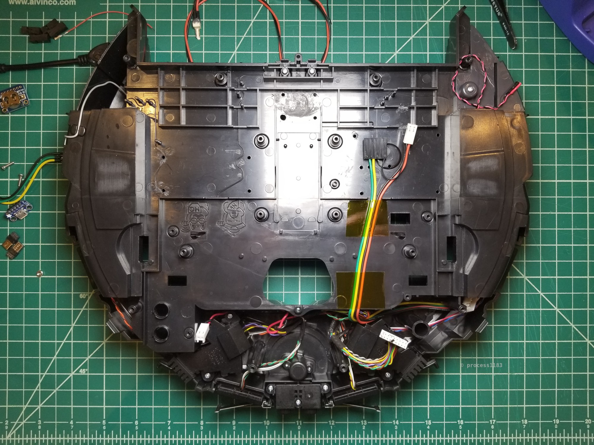
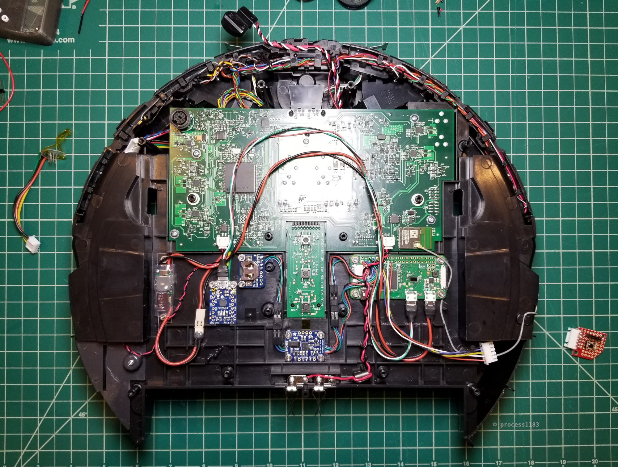
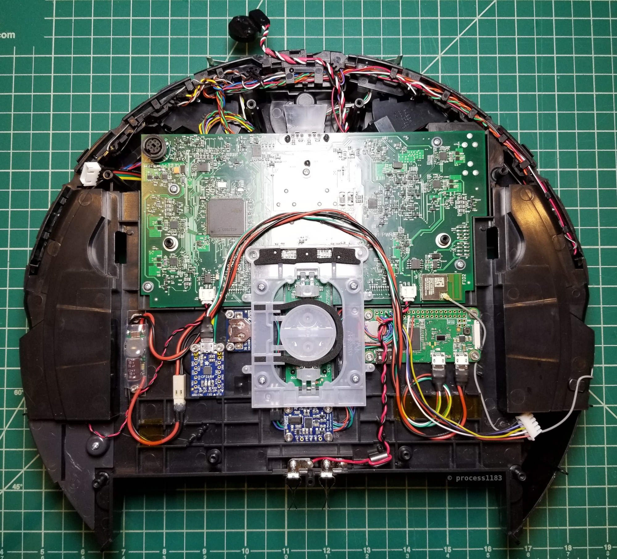
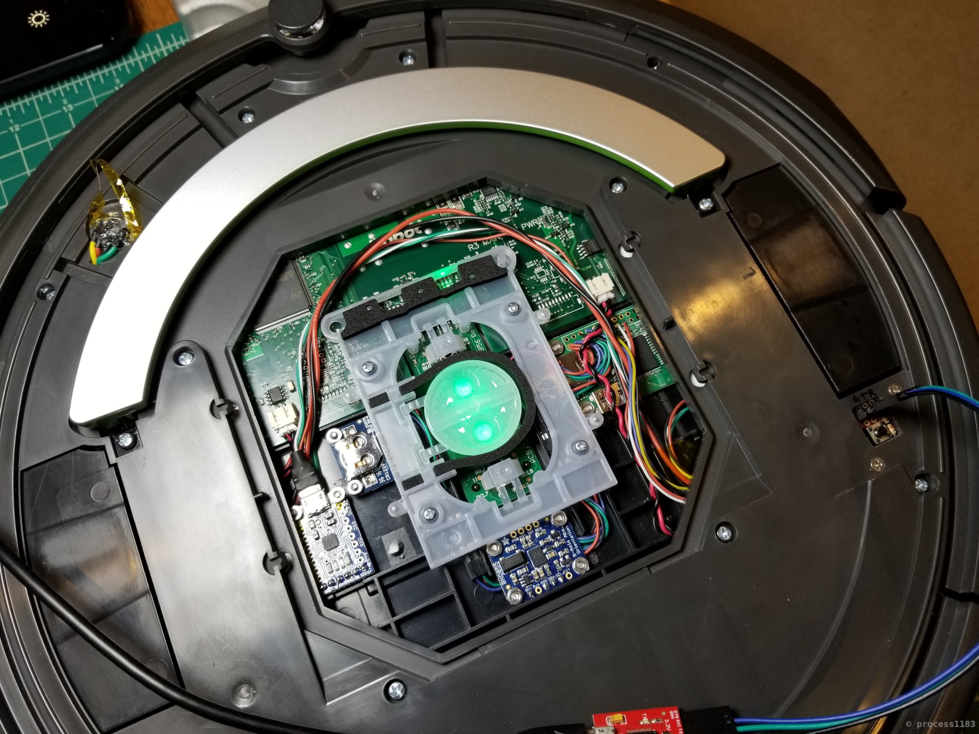
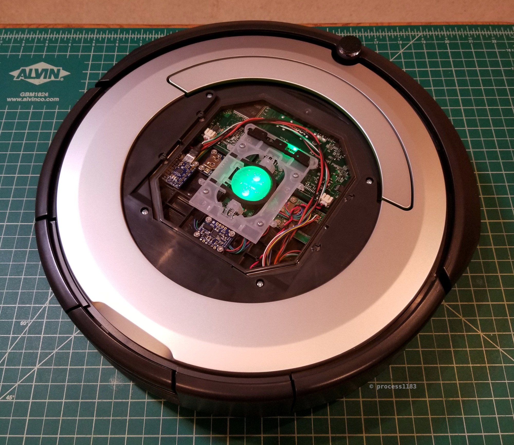
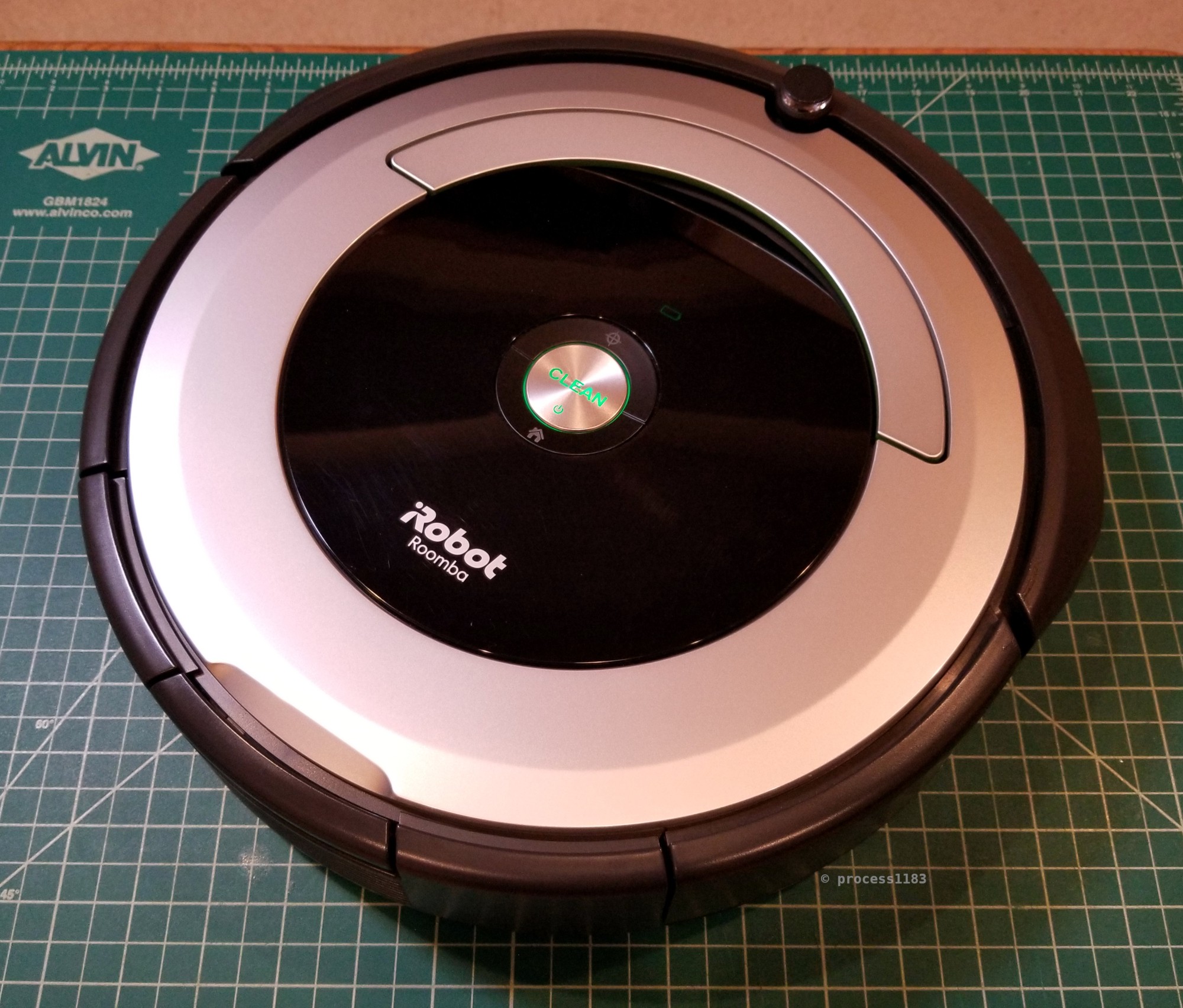
The purpose of this project is to enhance the functionality and capabilities of my iRobot Roomba 690 robot vacuum by adding a Raspberry Pi Zero 2W and IMU. One of the goals of this project is to be a 'stealthy' mod; I don't want there to be any external changes to the Roomba that could interfere with its primary purpose of, well, vacuuming. I have several goals in mind for this project:

  • No external changes to the Roomba, or changes that would adversely affect its vacuuming ability.
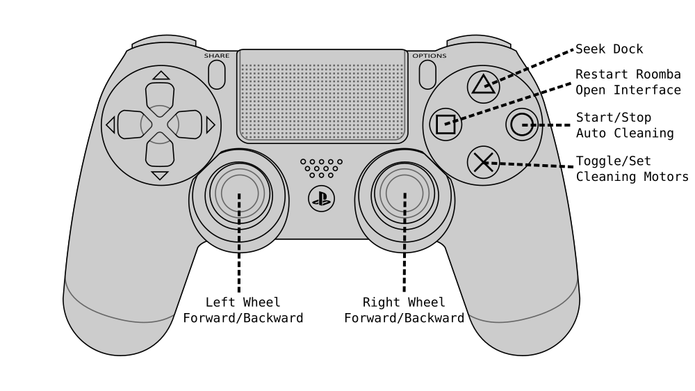
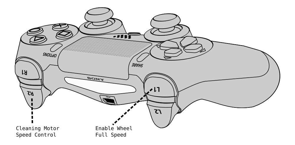
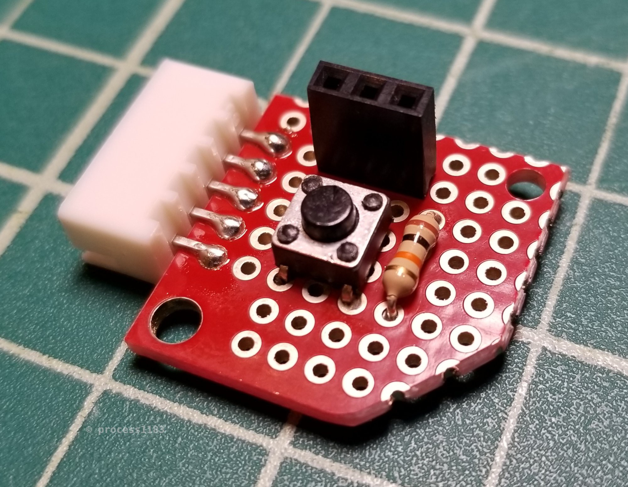
  • Enable remote control via a Bluetooth controller.
  • Use this enhanced Roomba as a platform for learning the Robot Operating System (ROS).
  • Connect the Roomba RPi ROS instance to Home Assistant Note: I know that the Roomba 690 has built-in WiFi and that there is a Roomba plugin for Home Assistant, however I was only able to get it to work for a short time before the Roomba Home Assistant plugin inexplicably ceased to work.
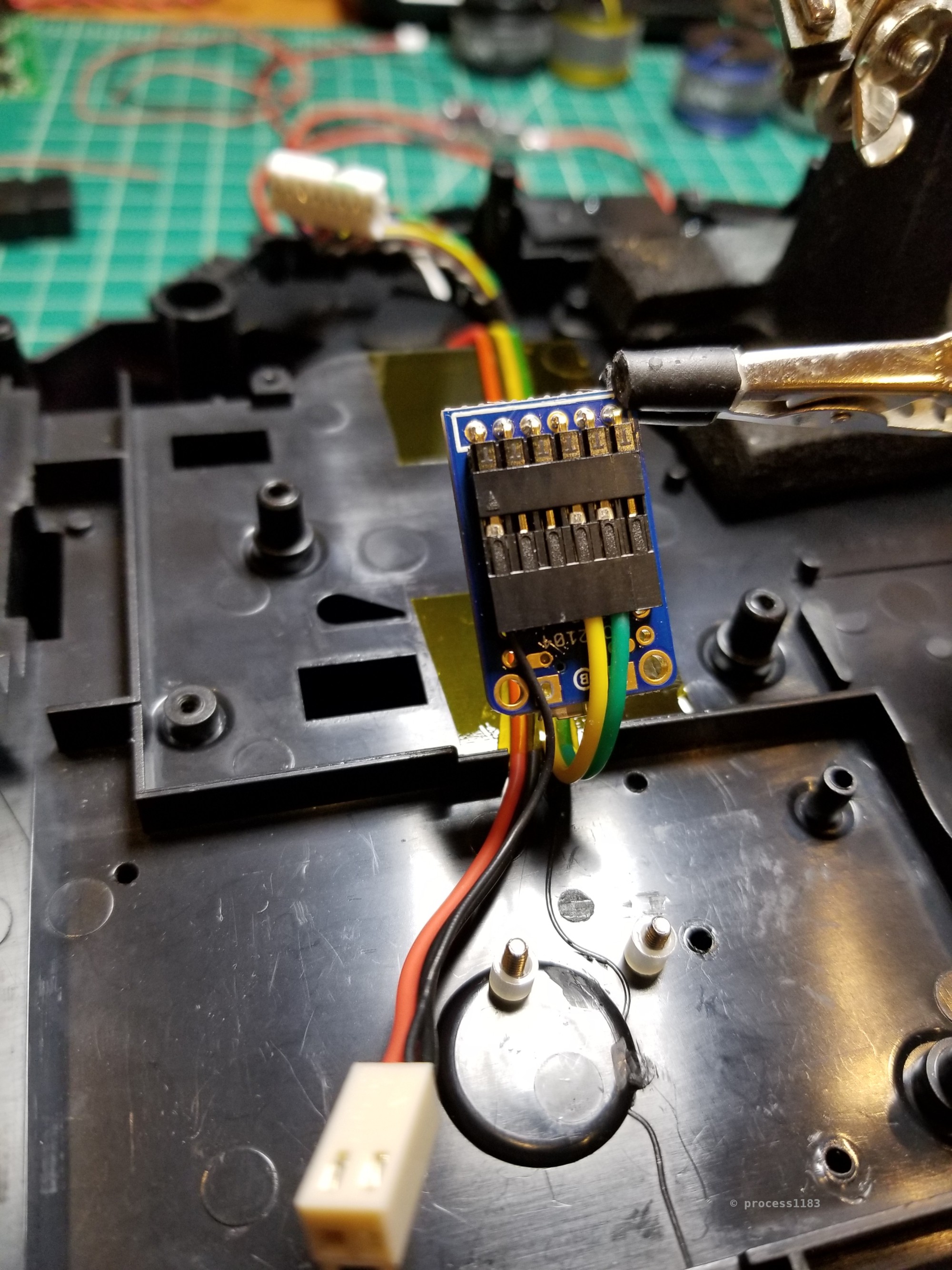
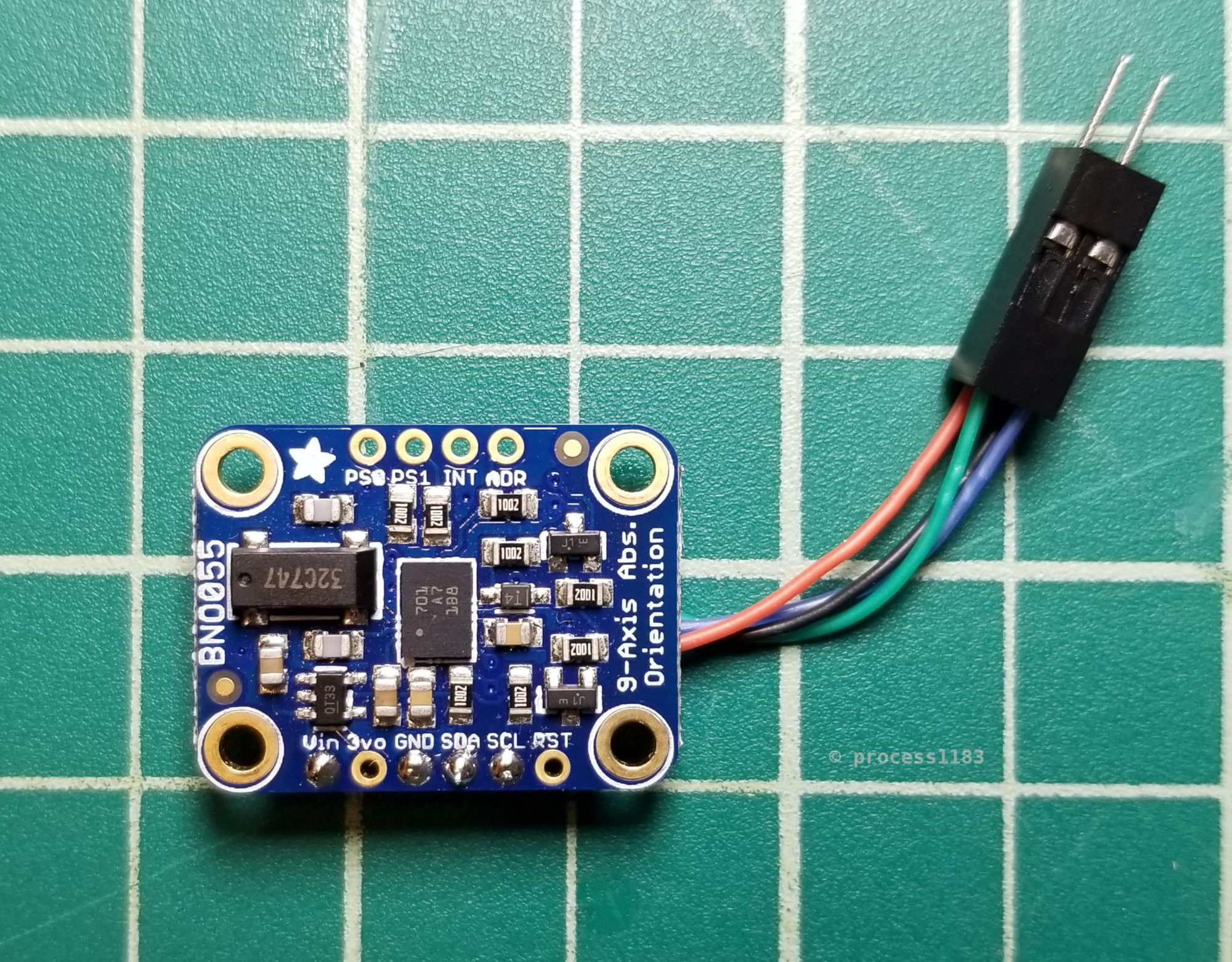
  • Use the added IMU plus the Roomba's built in sensors to improve the cleaning routine with inertial navigation.

Adobe Portable Document Format - 2.59 MB - 04/09/2021 at 04:41

Preview
Download

roomba-rpi-schematic.png

Roomba RPi electrical schematic.

Portable Network Graphics (PNG) - 417.69 kB - 03/31/2021 at 08:15

Preview
Download

  • Upgrades

    Josh Gadeken06/04/2022 at 13:48 0 comments

    I upgraded the RPi ZW to the new RPi Zero 2 to take advantage of the massive performance increase offered by the RP3A0 arm64 SiP [1]. Switching to an arm64 CPU and OS also means that my cumbersome cross-compilation environment is no longer needed! However, some ROS2 packages need much more RAM during build than the RPi Z2W has. My solution for this is to simply build the packages on a RPi 4, then copy the result to the Roomba's RPi Z2W. This is still easier and much more convenient than a cross-compilation system. An additional advantage of switching to an arm64 OS is that pre-built ROS2 binary packages are provided as an installation option [2].

    [1]: https://www.raspberrypi.com/products/raspberry-pi-zero-2-w/
    [2]: https://docs.ros.org/en/galactic/Installation/Alternatives/Ubuntu-Install-Binary.html


    Photo shows the RPi Zero 2W with heatsink in the Roomba chassis and the old RPi Zero 1W in the top right.

  • ROS2 Progress

    Josh Gadeken03/07/2022 at 13:12 0 comments

    I have been making some decent progress learning ROS2 and setting it up on the Roomba. As part of learning ROS2, I wrote a simple node for the BNO055 IMU based on the Adafruit CircuitPython BNO055 driver. Additionally, I detailed how to cross-compile ROS2 packages for the RPi ZW. The Roomba RPi ROS2 packages and documentation is in roomba-rpi/software/roomba_ros2/.

  • Building ROS2 for the RPi ZW

    Josh Gadeken07/26/2021 at 03:31 0 comments


    "ROS 2 Foxy Fitzroy Artwork" by Open Source Robotics Foundation is licensed under CC BY-NC 4.0

    Manually building ROS 2 [1] for the Raspberry Pi Zero W is necessary because Debian 10 Buster is a tier 3 platform [2]. This means that there are no officially built Debian 10 packages available.

    The RPi ZW's CPU is the BCM2835, which is an ARMv6 based CPU [3]. The Debian (and Ubuntu) armhf port does not support this CPU, and the armel port has poor floating-point performance [4]. Additionally, arm32 support in ROS is also tier 3 [2], so one couldn't simply use the ROS Ubuntu ARM packages (they are arm64 anyway).

    Debian does provide ARM cross-compilation tools, however they do not support the RPi ZW's CPU. Debian's `arm-linux-gnueabi-gcc` can produce binaries that run on the RPi ZW, but it does not support the VFP2 (Vector Floating Point) hardware extension of the RPi ZW's CPU (software floating point operations only) [5]. Debian's `arm-linux-gnueabihf-gcc` is built with VFP3 support, but it's for the ARMv7 [6], hence the need to build the cross-compiler toolchain from source. ROS has a cross-compiler toolchain, but like Debian's, it does not support the RPi ZW's CPU [7].

    The steps to set up a cross-compilation toolchain and build ROS 2 for the RPi ZW are detailed in roomba-rpi/docs/ros2_rpizw_build.md

    [1]: https://docs.ros.org/en/foxy/index.html
    [2]: https://www.ros.org/reps/rep-2000.html#foxy-fitzroy-may-2020-may-2023
    [3]: https://wiki.debian.org/RaspberryPi
    [4]: https://wiki.debian.org/RaspberryPi#Raspberry_Pi_issues
    [5]: https://gist.github.com/process1183/e224240df18483e57fa2872fb4d89023#file-debian-gcc-arm-linux-gnueabi-versions-txt-L18
    [6]: https://gist.github.com/process1183/e224240df18483e57fa2872fb4d89023#file-debian-gcc-arm-linux-gnueabi-versions-txt-L70
    [7]: https://github.com/ros-tooling/cross_compile#supported-targets

  • Roomba Remote Control

    Josh Gadeken04/08/2021 at 07:22 0 comments

    One of the goals of this project was to enable remote control of the Roomba with a DualShock 4 connected over Bluetooth. I wrote a Python program to read the controller and command the Roomba. The code is in this project's GitHub repo: github.com/process1183/roomba-rpi/tree/master/software/roomba_remote_control. The full documentation for the Roomba Remote Control program is also in this project's GitHub repo: github.com/process1183/roomba-rpi/blob/master/docs/roomba_remote_control.md

    This work, "DS4 RRC Layout", is a derivative of "Dualshock 4 Layout" by Tokyoship, used under CC BY 3.0. "DS4 RRC Layout" is licensed under CC BY 3.0 by Josh Gadeken.

    This work, "DS4 RRC Layout 2", is a derivative of "Dualshock 4 Layout 2" by Tokyoship, used under CC BY 3.0. "DS4 RRC Layout 2" is licensed under CC BY 3.0 by Josh Gadeken.

  • Build Recap

    Josh Gadeken04/08/2021 at 07:12 0 comments

    The first step of this project was to disassemble the Roomba to clean it (there was a large amount of dust build up from doing its job.) After cleaning, I needed to see if there was even room in the chassis for the RPi, IMU, and supporting components. There is! I also played around with a few arrangements before settling on the RPi on the Roomba's right side, the IMU in the center behind the button board, and the rest of the components on the Roomba's left.


    There's just enough room underneath the Roomba's motherboard to run the Open Interface wires from the front of the Roomba to the open space where the additional hardware will be installed.

    Note: This photo was taken near the end of the build, after the component choices and locations were finalized. This is why all the drill holes are present.


    The connection to the USB serial board is nice and compact thanks to right angle headers.


    The two I2C connectors and the power button and serial board connector soldered to the Raspberry Pi Zero W.


    This simple and small PCB makes the RPi's serial port and shutdown button toollessly accessible.

    The serial and shutdown button board is installed in the Roomba's top cover behind the right wheel module.


    To save on bulk, I soldered a custom micro USB OTG cable to connect the Adafruit CP2104 serial board to the RPi.


    The DS3231 RTC board (not pictured) and the BNO055 IMU board both connect to the RPi through 2x2 connectors.


    This is the custom low-profile 'mini-DIN 7' connector the I put together after failing to find any comparable existing option. It's janky AF, but it works. To create this, I cut out a small plastic disk that fits right above the Roomba's mini-DIN connector, then marked the pin locations and drilled tiny holes in the disk. Next, I bent some scrap leads into place and soldered the four wires to the 'pins'. In this connector, pins 1 and 2 (Vpwr) are soldered together with the red wire, and pins 6 and 7 (GND) are soldered together with the black wire (pinout is on page 3 of the iRobot Roomba 600 Open Interface Spec). Finally, I added a loop of tape to enable easy removal of the connector. This custom connector does not fit through the Open Interface connector hole in the Roomba's top cover, so it uses an inline JST connector, which does fit through the Open Interface chassis hole.


    Here's the Roomba with all the additional components installed (minus the serial and power button board on the right).

    The I2C wiring fits nicely beneath the Roomba's clear button shroud. I also slightly overestimated the required length of the micro USB OTG cable, which is why it needed to be coiled behind the RPi.


    All of the machine screws that I used were countersunk into the plastic chassis. The countersinking was required because there's no extra room between the brush module and the chassis.


    With the Roomba almost fully reassembled, you can see that the Open Interface connector, serial and shutdown button board, and most of the new components can be easily accessed.

    The two plastic top covers snap into place. The outer silver plastic ring that conceals the Open Interface connector and RPi's serial port and shutdown button is trivially removed by hand. The center black logo and button cover is a little more difficult to remove, but can be done with a plastic spudger.

    As intended, the completed Roomba with RPi looks no different externally than a stock Roomba 690.

View all 5 project logs

Enjoy this project?

Share

Discussions

Simon Jansen wrote 08/30/2022 at 06:37 point

Cool to see we have similar goals, yet a different approach to a solution :) You're going the full ROS/Raspberry route, and I'm doing the Arduino/ESP8266 thing.
https://hackaday.io/project/183524-controll-yer-roomba-600-series-with-esp8266
I've got the Home Assistant integration pretty figured out though. Using MQTT with autodiscovery works great. Check out my project for examples on event-triggers, sensordata, actions/buttons and a camera-entity as a map.
Do you have any results or progress for navigation/mapping and integration of IMU and wheel-encoder data? I'm curious if adding a cheap IMU will be accurate enough to do a map of a full cleaning session.

  Are you sure? yes | no

Josh Gadeken wrote 10/01/2022 at 16:10 point

Thanks for the info about your Roomba 632 + ESP8266 project! I have not had much time to work on this lately. The next steps for my project will be experimenting to find out how to shield the IMU from the main brush motor, since when it's running, it completely throws off the magnetometer. I also need to continue writing a URDF file for use with the `robot_localization` ROS2 package: https://github.com/cra-ros-pkg/robot_localization/ which can be used to fuse the wheel odometry with the IMU data.

  Are you sure? yes | no

Jon Steel wrote 06/10/2022 at 05:35 point

This is Great! I really appreciate your vision on this project. It provides a lot of inspiration for my Robot vacuum hacking project!

  Are you sure? yes | no

Josh Gadeken wrote 06/10/2022 at 15:12 point

Thank you- I'm glad you find it inspiring! Good luck with your Shark 'bots!

  Are you sure? yes | no

Similar Projects

Does this project spark your interest?

Become a member to follow this project and never miss any updates