 Dominik Meffert
Hi there,
It has been over a year since I worked the last time on this project, but did so in the last few weeks and now I have an update ready.
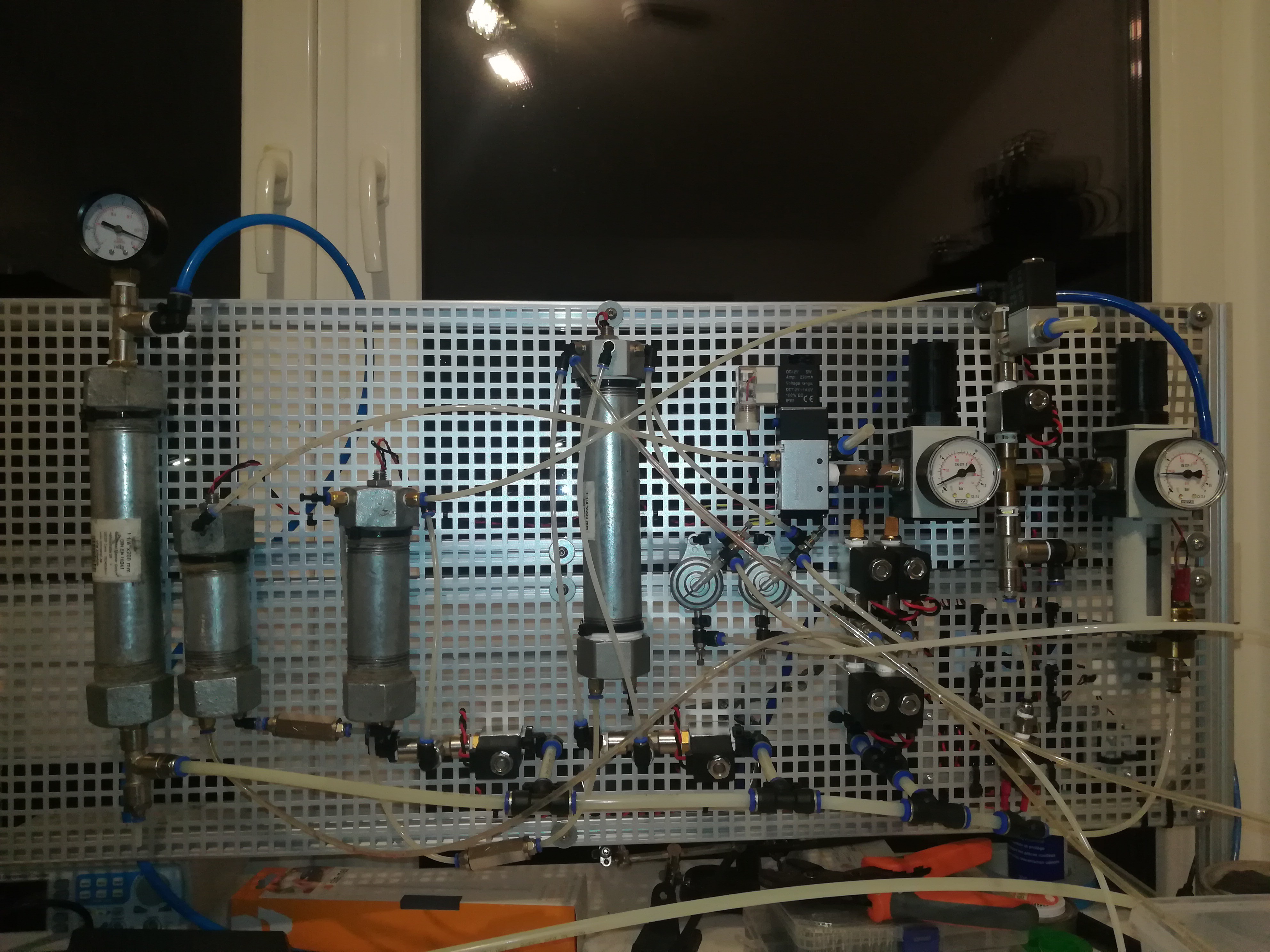
New Ink Pump and simplified Design
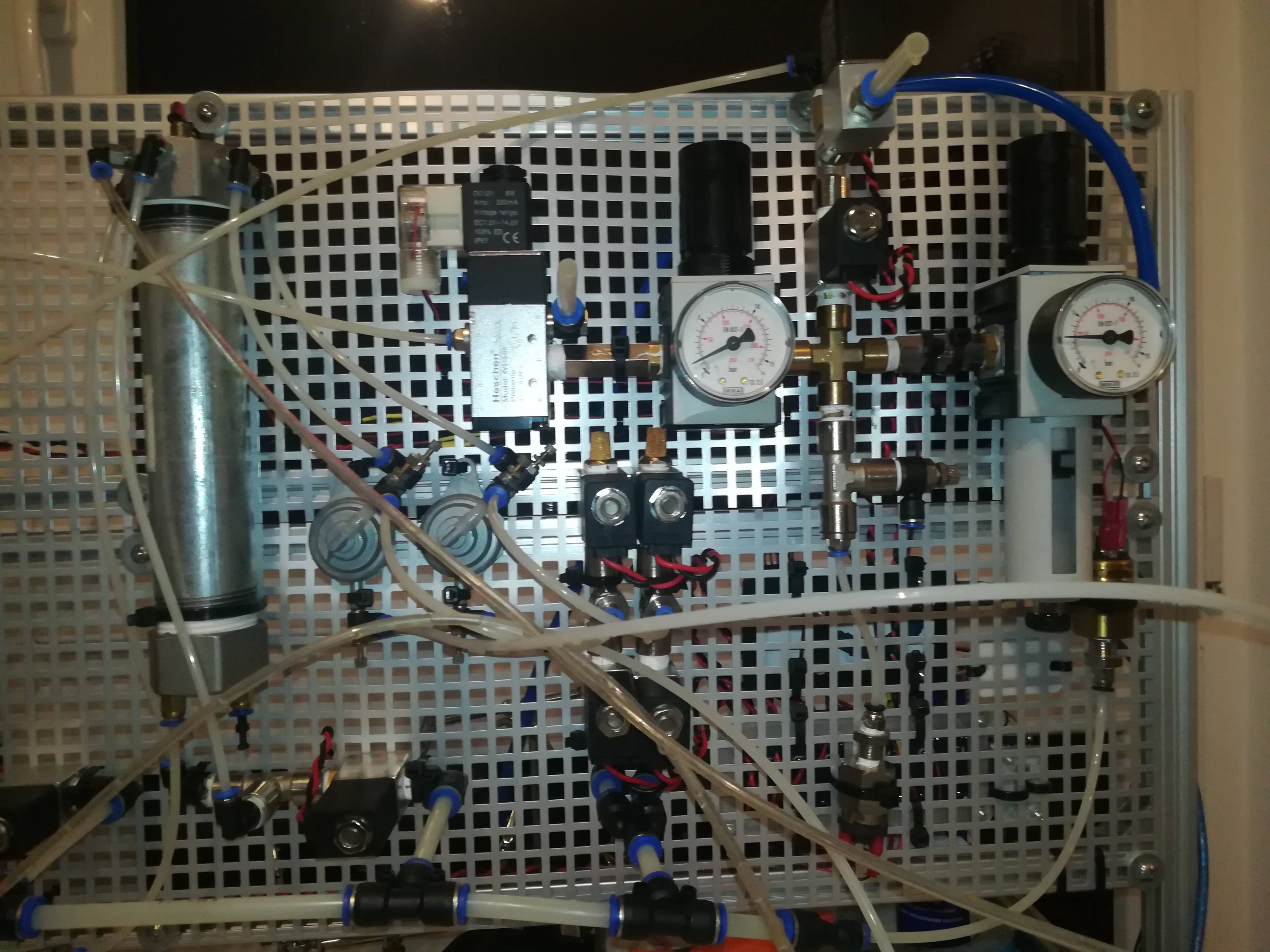
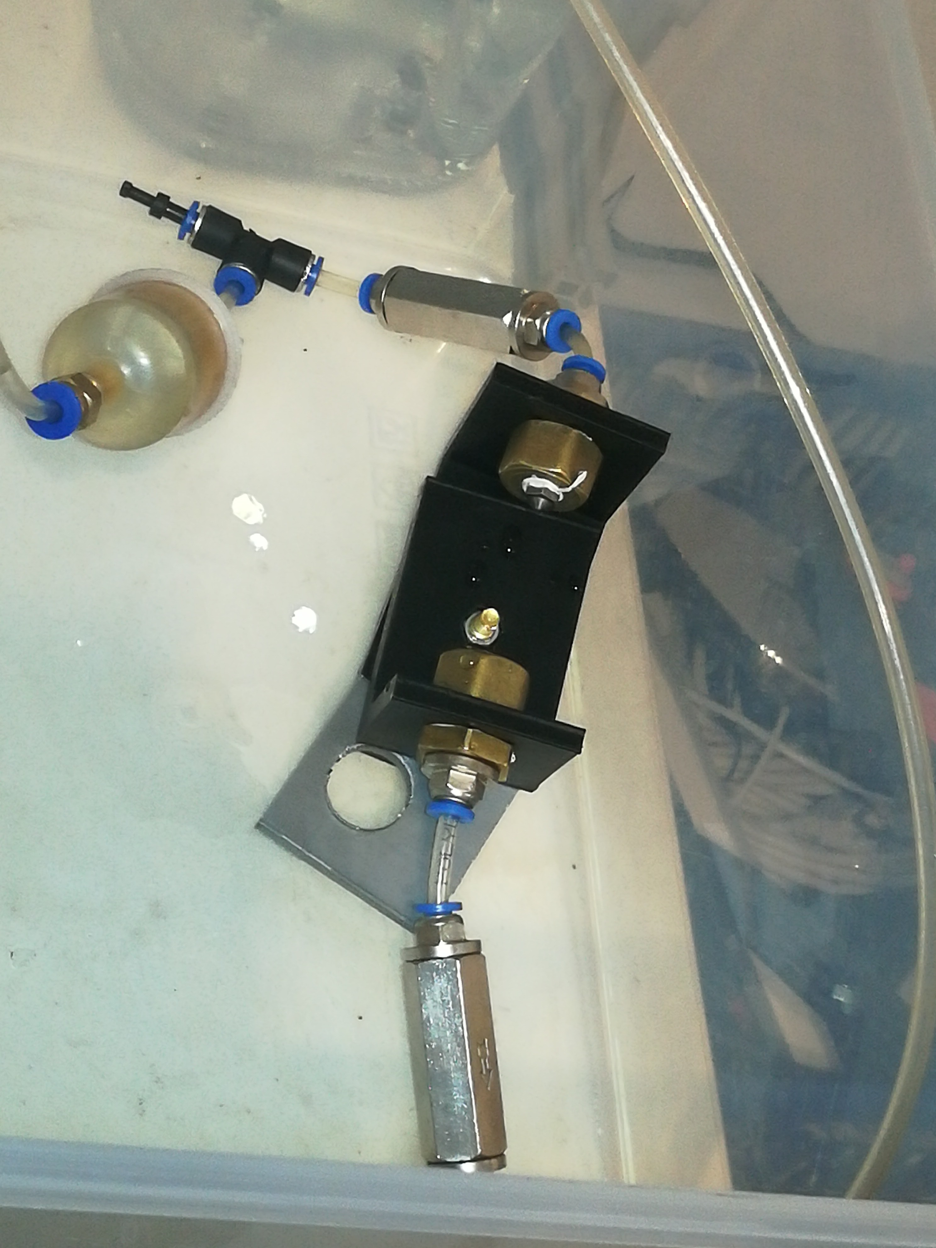
In 2021 I faced two problems for which I had no solution at the time. One was the pump and the other one was the software setup. The old pump's design consisted of a pneumatic piston that pulled and pushed a syringe. The problem with it was that it was leaking and also not powerful enough to push the ink/water into the pressurized timer chamber. I replaced it with a 1 1/4" pipe that can be set under vacuum, to pull in ink from the reservoir which is always under vacuum, and also can be set under pressure higher than the pressure of the timer chamber which is always pressurized. It can also be vented after transferring the ink/water to prevent the breakup of the vacuum the next time it has to be set under vacuum.
I also replaced the timer which was made of a small PTFE tube with a self-made magnetic float by another 1 1/4" pipe to further simplify the design.
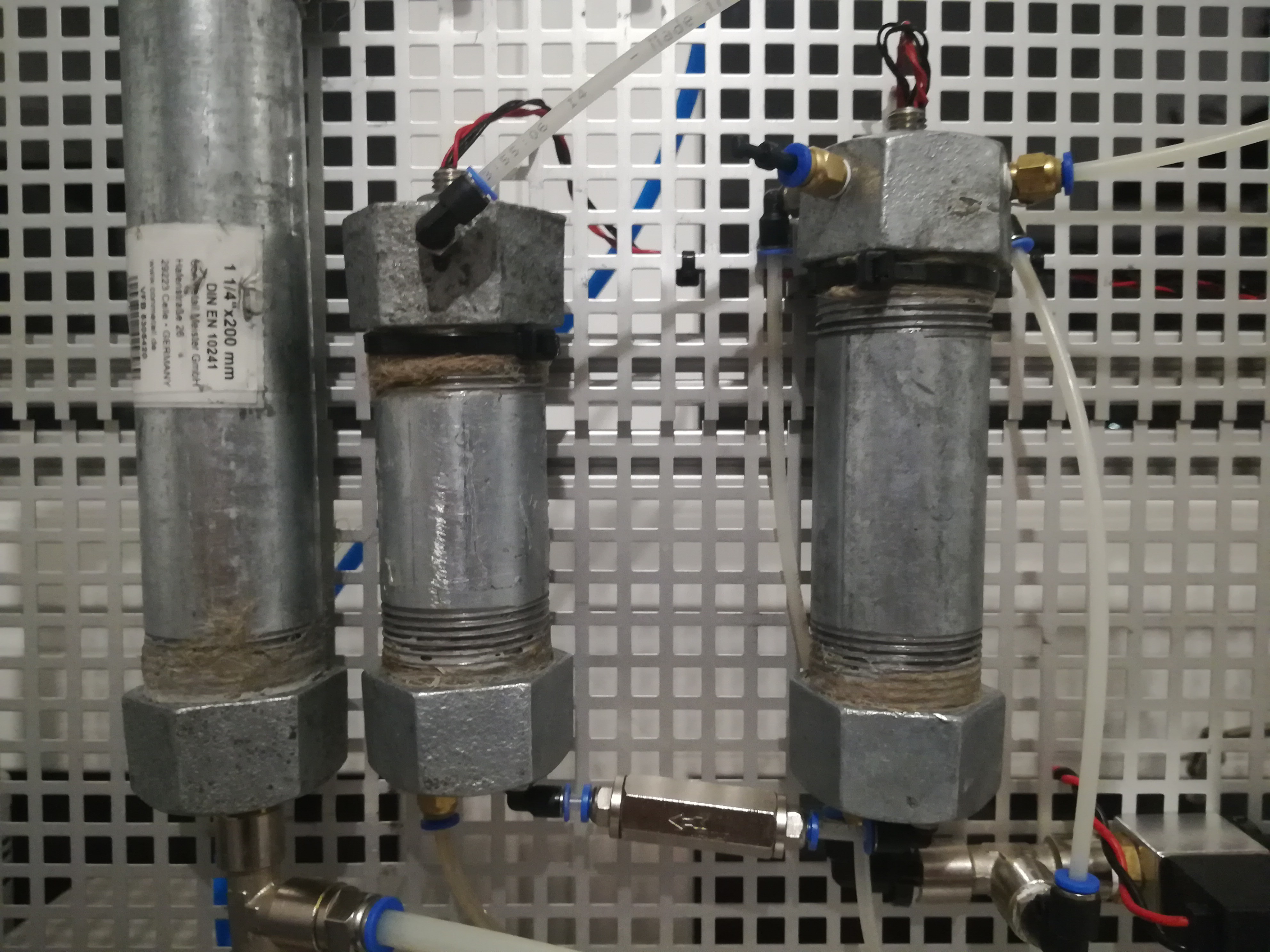
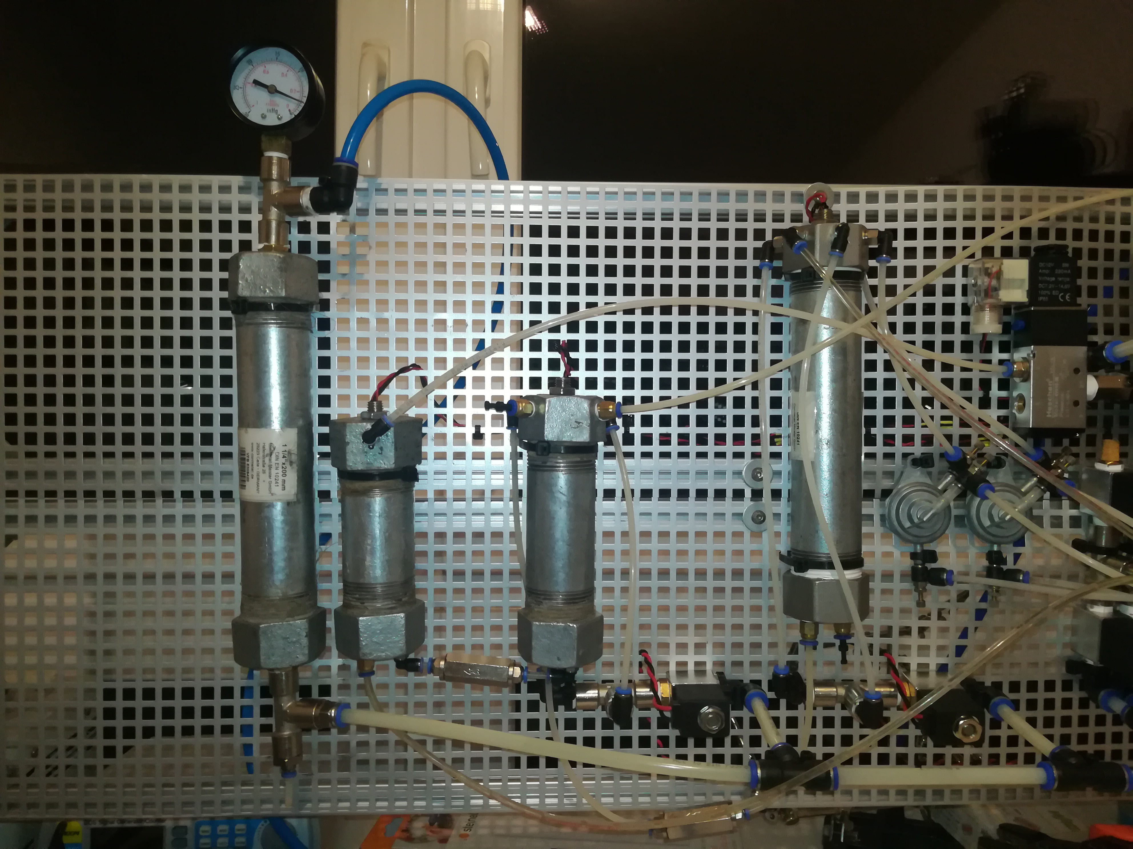
The pipe on the left is just a puffer to stabilize the vacuum - also made from a 1 1/4" 200mm pipe.
I used pipes in 3 different sizes 200mm for the reservoir, 120mm for the pump, and 100mm for the timer. All three pipes contain a 100mm double float switch. The reservoir is the largest tube because it has to contain enough ink/water to fill up an empty pump to the pump's upper float switch when the reservoir is filled to its lower float switch.
For the reservoir, the lower switch is used to detect when it has enough liquid in it to fill up the pump and the upper switch is used to tell the system and the user that it can not handle much more liquid.
The pump is a bit larger than the timer. Both pipes have the same 100mm double float switch so that if the liquid from the pump is transferred to the timer some liquid remains in the pump when the ink level gets below the pump's lower float switch. So, I've chosen a bit larger pipe for the pump to prevent a condition where there is just a bit too little liquid in the pump to fill up the timer to the upper switch which would lead to a failure of the system.
MakeUp Add Cycle Theory
My current plan for the ink cycle is to check the level of the reservoir when the timer is empty. Normally it should be filled to the lower switch at that point. If not the machine should add ink. If it is filled to the lower switch it should add make up or ink for a set time according to the viscosity flow time measured by the timer - the time that the ink level takes to drop from below the upper switch of the timer below the lower switch of the timer. If the ink level in the reservoir reaches the upper switch the system should stop adding fluid even if it would be needed to match the desired viscosity until there is enough space in the reservoir to add more fluid. If the viscosity of the ink in the system reaches a value close to the desired flow time it should stop adding ink or make up until it is required again. If the flow time is too low it should add ink instead of makeup. Doing so should ensure a constant viscosity. The ink in the ink bottle should be close to the desired viscosity so that the initial fill of the system would not lead to a viscosity far off from the desired viscosity and a long time of adding solvent until the desired viscosity is reached. The whole adding makeup/solvent thing should only be for making up evaporated solvent and I want to do it in a way that does not add more complexity to the system.
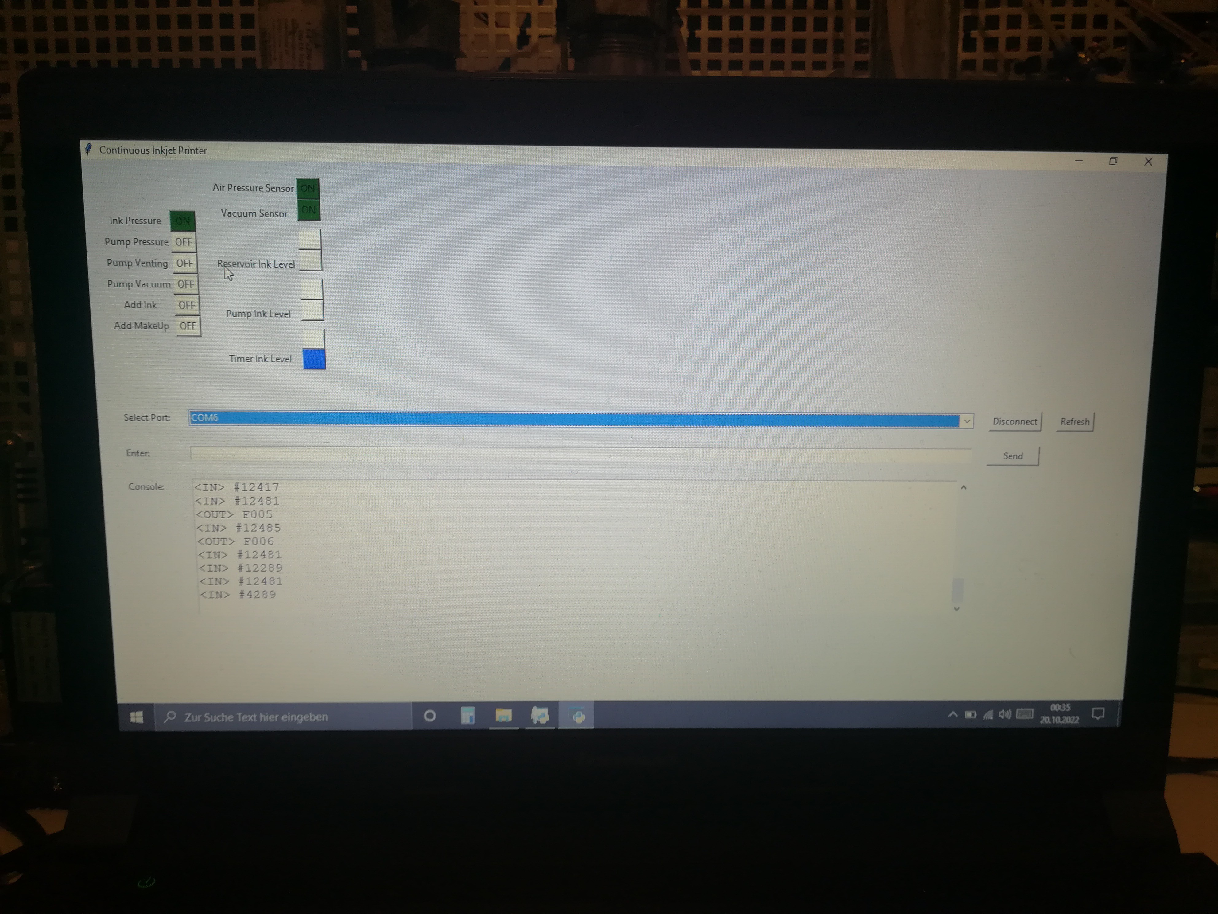
Arduino + PC GUI instead of Raspberry Pi
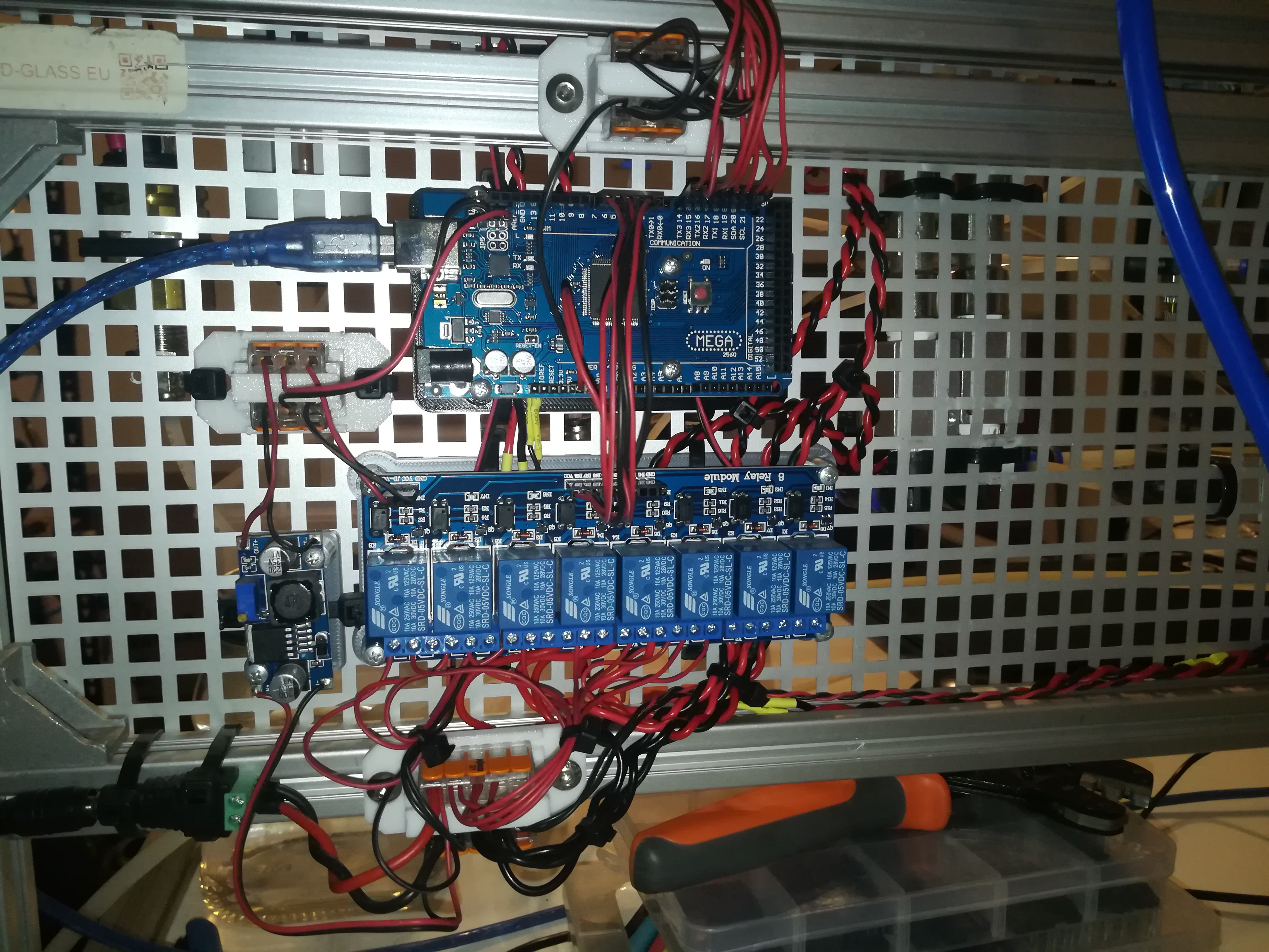
I decided to use an Arduino MEGA + a Python GUI for PC that I'm writing at the moment instead of a Raspberry Pi, because I'm much more familiar with this kind of setup. Doing so I can control the machine like a 3D printer or CNC machine via serial and GCODE-like commands (I'm sending Fxxx commands for controlling the valves + operation and receiving binary-based #xxxxx values for showing the status at the moment * and I will also add $xxxxxx values for the flowtime in milliseconds and maybe @xxxx commands for sending text or so...)
Discussions
Become a Hackaday.io Member
Create an account to leave a comment. Already have an account? Log In.