 Dominik Meffert
The current printer is powered by pressurized air from an air compressor and vacuum from a vacuum pump. Both the pressurized air and vacuum are used to move the ink around.
The pressurized air pushes the ink from the ink tank to the printhead and through the nozzle forming the ink stream that hits the opening of the gutter. From there the ink gets drawn into the reservoir tank by vacuum. It gets collected there until the ink tank needs to be refilled. Then the ink gets drawn from the reservoir tank into the pump tank by vacuum. When the pump tank is filled, pressurized air with a higher pressure than that of the ink tank is applied to the pump tank to pump the ink from the pump tank into the ink tank.
Compared to that, the new hydraulic-powered printer is much simpler since it uses ink as a hydraulic fluid. This way the pressurized ink can be taken from the hydraulic system which can also generate the vacuum that is needed for drawing the ink back into the system by the use of a hydraulic-powered venturi pump.
Because of that, there is no need for a separate vacuum pump or air compressor which will make the printer cheaper, less complex, and more compact.
All it needs is a powerful ink pump and a low-pressure air pump to power the hydraulic-powered printer.
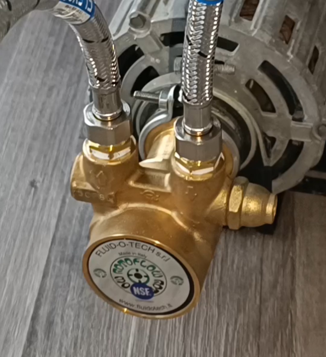
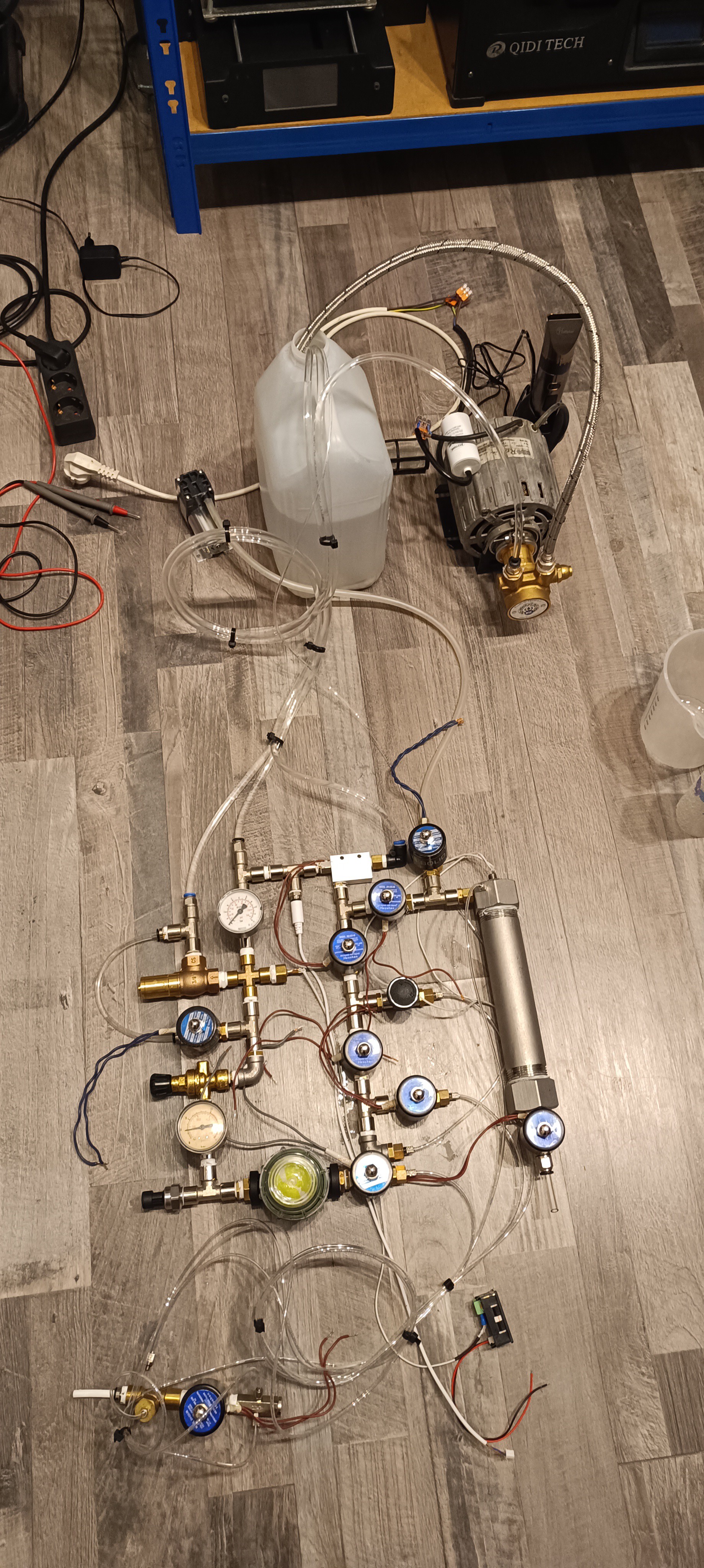
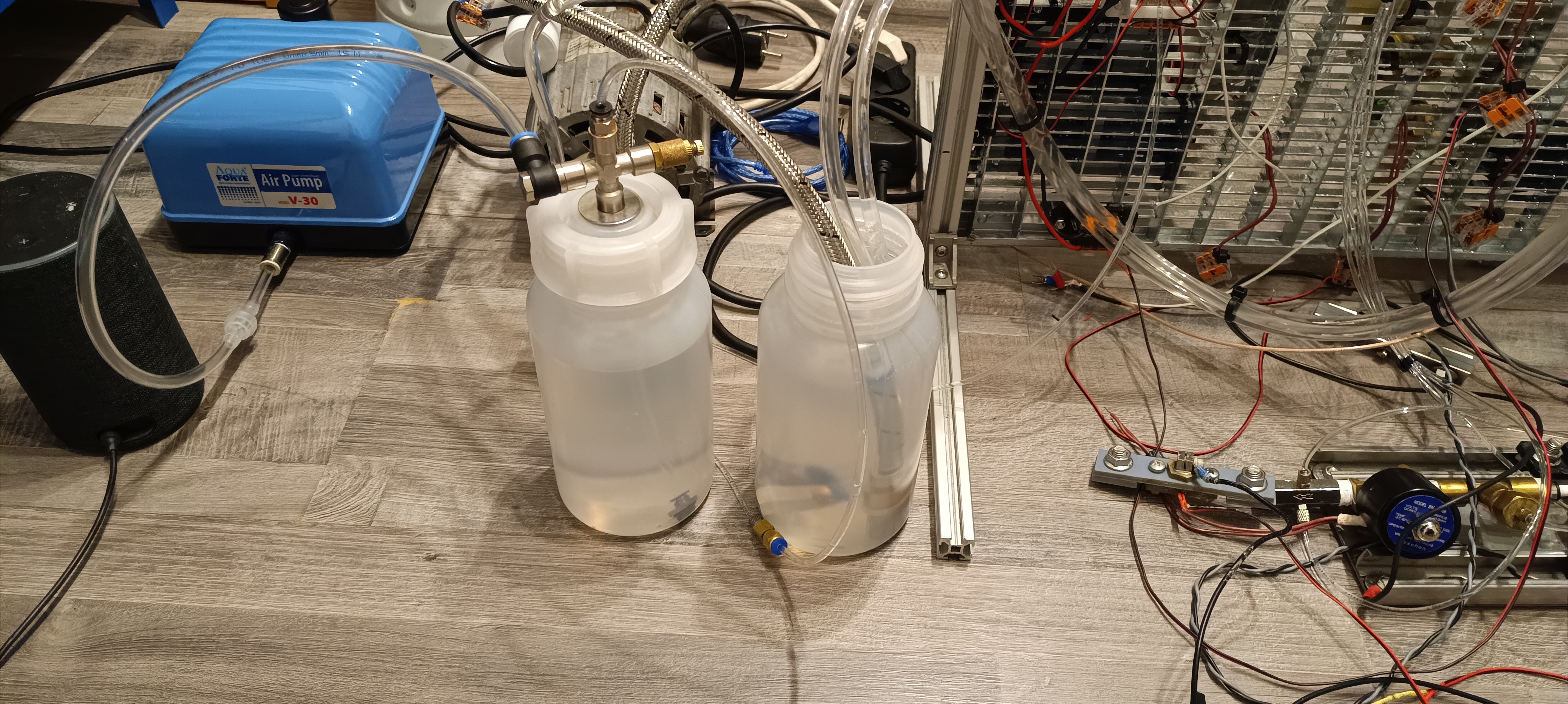
For that, I used a Fluid-O-Tech rotating vane pump (200l/h) and an AquaForte v30 pond air pump.

Until lately, I didn't know anything about hydraulic systems and so I thought the pump's output would have to go directly to the nozzle, which would have made finding a suitable pump very hard, but just a few weeks ago I read an article about RC hydraulic systems where they used a relief valve for limiting the hydraulic pressure by feeding some of the pump's output back to the tank.
This makes everything easier because, by the use of such a relief valve, a pump running at a constant speed and a much higher flow rate than that what is used by the ink stream can be used for powering the system.
The same can also be done by the use of fixed restrictions and a PWM-controlled pump, but since the constant flow pump + relief valve were cheaper, I used this method.
After reading about the relief valve I looked for such a valve, but since hydraulic system relief valves are usually designed to work at high pressures e.g. from 10 to 200 bar I had to look for a relief valve that is designed to work at low pressures and so I bought a water relief valve that is designed to work from 2 to 8 bar.
The valve I got works by opening up just enough to keep the pressure before the valve at the set level. When now some valve opens up to supply e.g. the venturi pump, printhead, or viscosimeter with ink, the relief valve restricts the flow out of it to keep the pressure of the system at the set level. It has a "screw" at the top that compresses a spring for setting the pressure.
The valve was the first element of the new printer design and after confirming that it worked the way I thought it would, I ordered a venturi pump for testing both together to see if I could get the set system pressure and the needed vacuum for the printer from those two parts.
The venturi pump can generate a vacuum by the use of a gas or fluid that "draws" the air with it when it is ejected from a small nozzle into a narrowing and then expanding tube.
I was a bit worried if it would work at all since the type of venturi pump I used is intended to be used with pressurized air, but it turned out to work pretty well with water when I tested it out.
With that, I could confirm that just a supply of fluid at the right pressure and flow rate can be used to power the printer.
After testing out the relief valve and venturi pump, next up was finding the right ink pump.
This was not that easy, because the pump has to provide some capabilities to be suitable for the task:
- It has to provide at least 40 psi of pressure.
- It has to provide a flow high enough to power the venturi pump, printhead, and viscosimeter.
- It needs to be able to run continuously for a long time.
- It needs to be able to handle solvents and flammable liquids like ethanol-based ink.
First, I thought about using a multi-chamber diaphragm pump, because these pumps are not that noisy and can provide the needed pressure, but since all pumps, I could find claim to be not suitable for flammable liquids, they were not an option.
Later, I found out that there are specialized diaphragm pumps for lab and industry use that can handle flammable and corrosive liquids, but they are also very expensive.
After more searching, I ordered two hydraulic pumps, one RC hydraulic pump driven by a BLDC motor and another hydraulic pump without a motor.
After getting everything ready for running the pump I connected the pump to the relief valve, set the pressure to 40 psi, and let it run for a while.
At first, it looked very promising, but it didn't take long until it became visible that the gears were wearing down rapidly.
The water got darker from metal particles, the pump started stalling from time to time until it finally failed.
So, it seems like this pump can only be used with hydraulic oil and not with water or ethanol.
For testing out the second hydraulic pump I connected it to the relief valve, set the pressure to 40 psi, and connected it to a small AC motor with a GT2 belt. Shortly after, I realized that this pump stalls as soon as there is force applied to the side of the shaft (by the belt in this case).
So, I tried driving it with the AC motor directly, which unfortunately was not able to drive the pump.
Because of that I tried driving the pump with a small DC motor, which could drive the pump, but was also a bit weak so that the speed at the point of highest resistance in the rotation was a bit lower so that the pressure was varying a lot.
Later, I found out that the motor that is usually used for driving this kind of pump is much more powerful than the motors I used for testing.
What I learned from this test and the search for the pump is that pumps like these are sold in two ways, separately and also together with the right motor. I think this is done so you don't have to buy both the pump and the motor if only the pump needs to be replaced.
While testing out the last hydraulic pump, I was worried about corrosion, since the one I got seemed to be made out of cast iron, and while the ink with the sodium acetate is no longer that corrosive against brass, aluminum, and copper, it still is corrosive against iron which even starts rusting when it comes in contact with tap water.
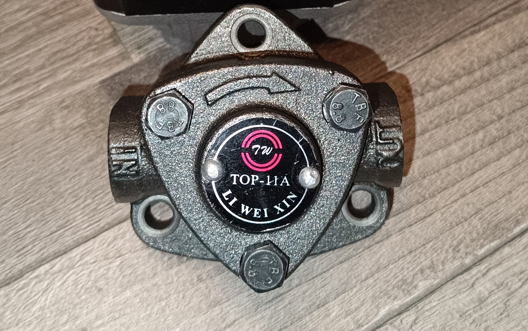
Because of that, I searched for other pumps and saw that there are rotating vane pumps available made out of either stainless steel or brass which can provide the needed pressure, flow, and chemical resistance while at the same time being able to run continuously and being able to handle flammable liquids like gasoline and ethanol.
The problem at this point was that I did not know where to get the motor for these since I found the pump by accident and never saw the pump + motor assembled.
So, I spent some more time searching until I finally found the same pump type used in portafilter coffee machines.
With this in mind, I searched for a used portafilter coffee machine pump and ordered a cheap one.
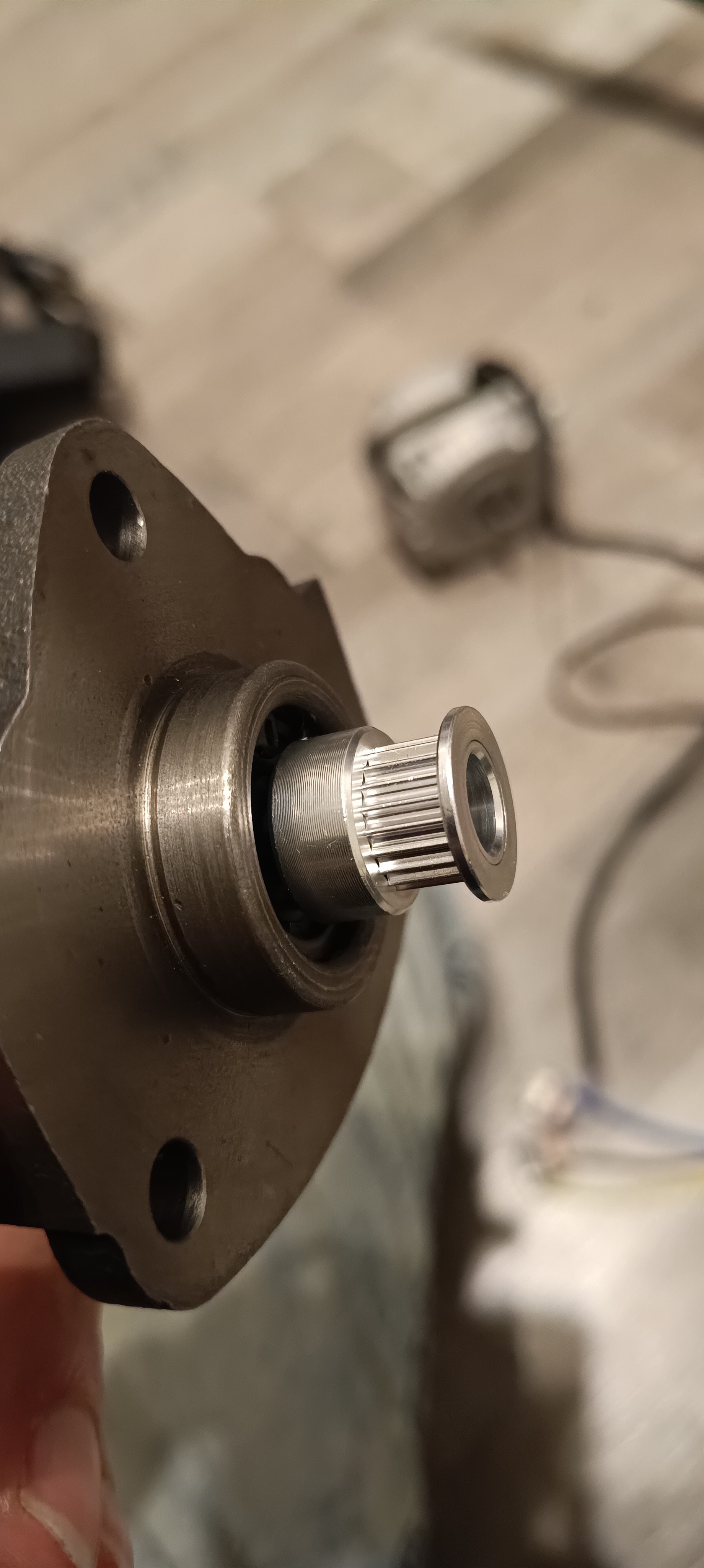
After a few days, the pump arrived, but something was wrong... the motor got delivered without its capacitor.
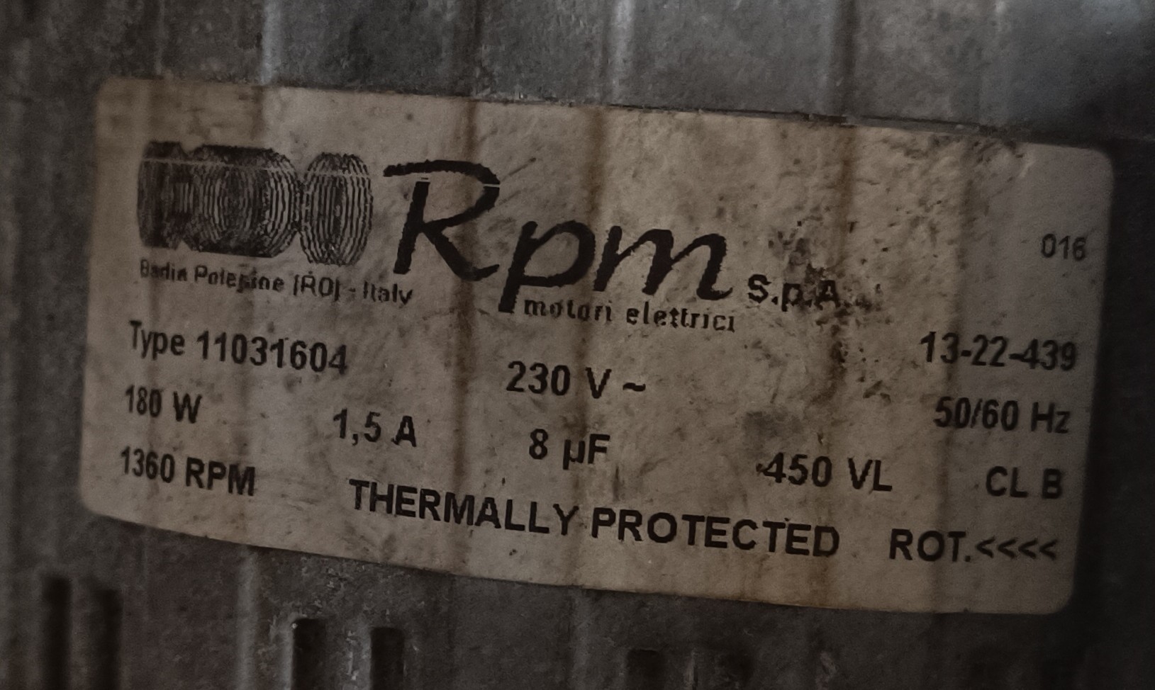
So, I ordered a new capacitor and started the motor, but there was still something wrong...
the pump connected to the motor was broken.
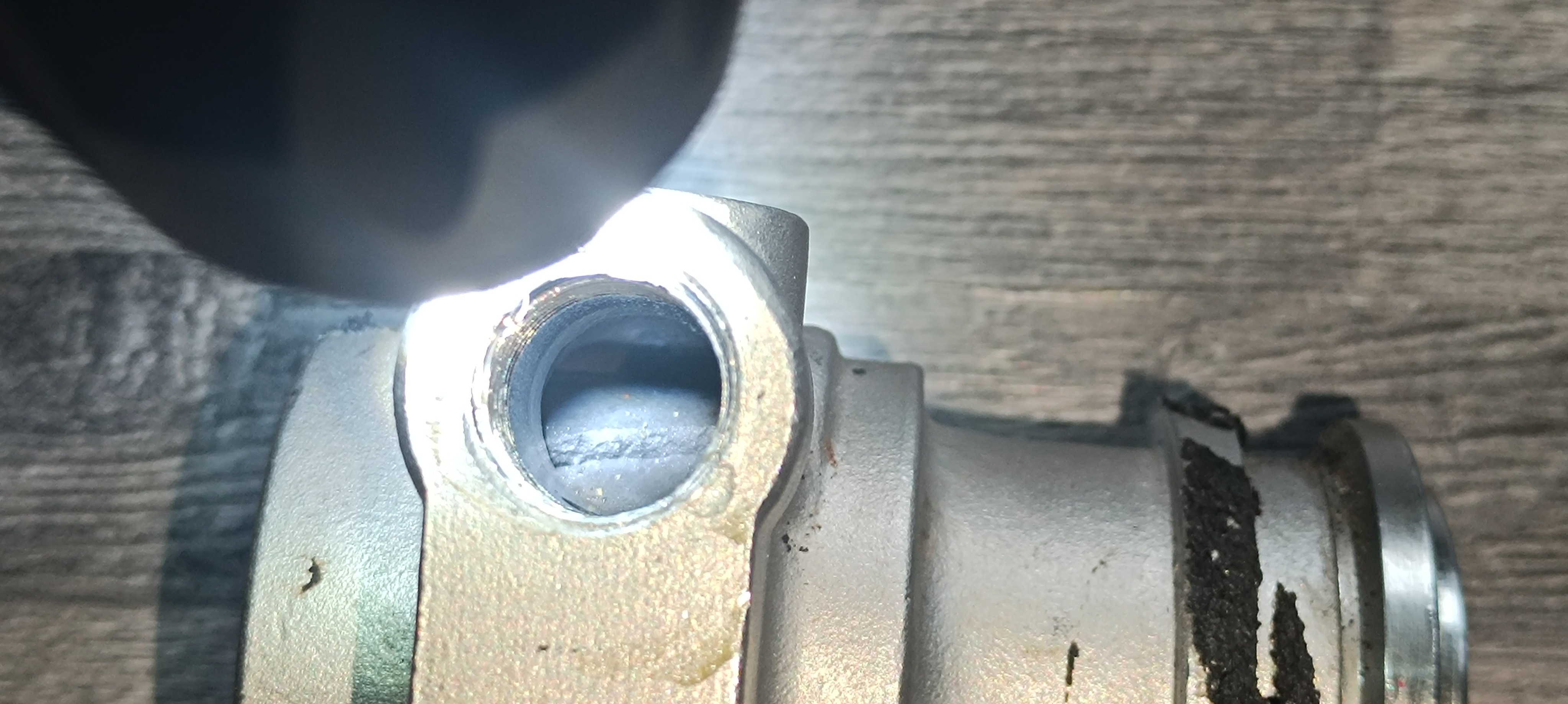
Now the knowledge about the offer for the pump I saw before came in handy. I compared the dimensions of the pumps' "mounting rings" and they seemed to be identical.
So, I ordered the pump I saw before.
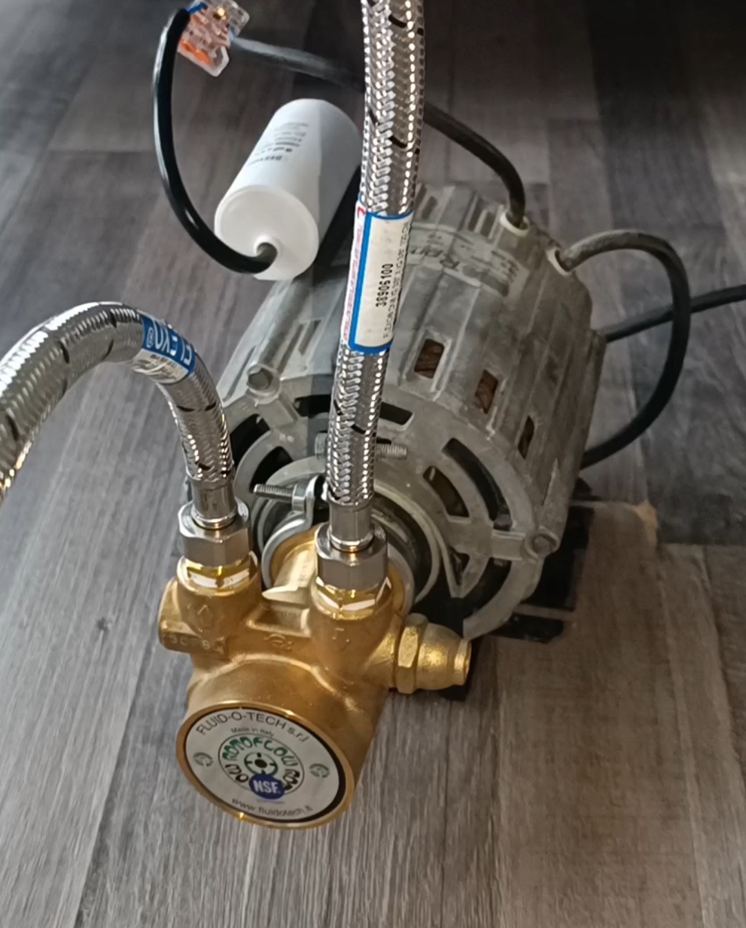
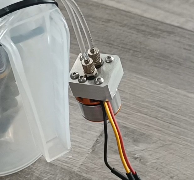
When I then mounted the new pump and started the motor it finally worked.
The pump is now able to run continuously without overheating and can deliver the needed flow and pressure. Together with the relief valve and venturi pump it can supply all that's needed for running the printer, so I could finally start building the new hydraulic-powered printer.
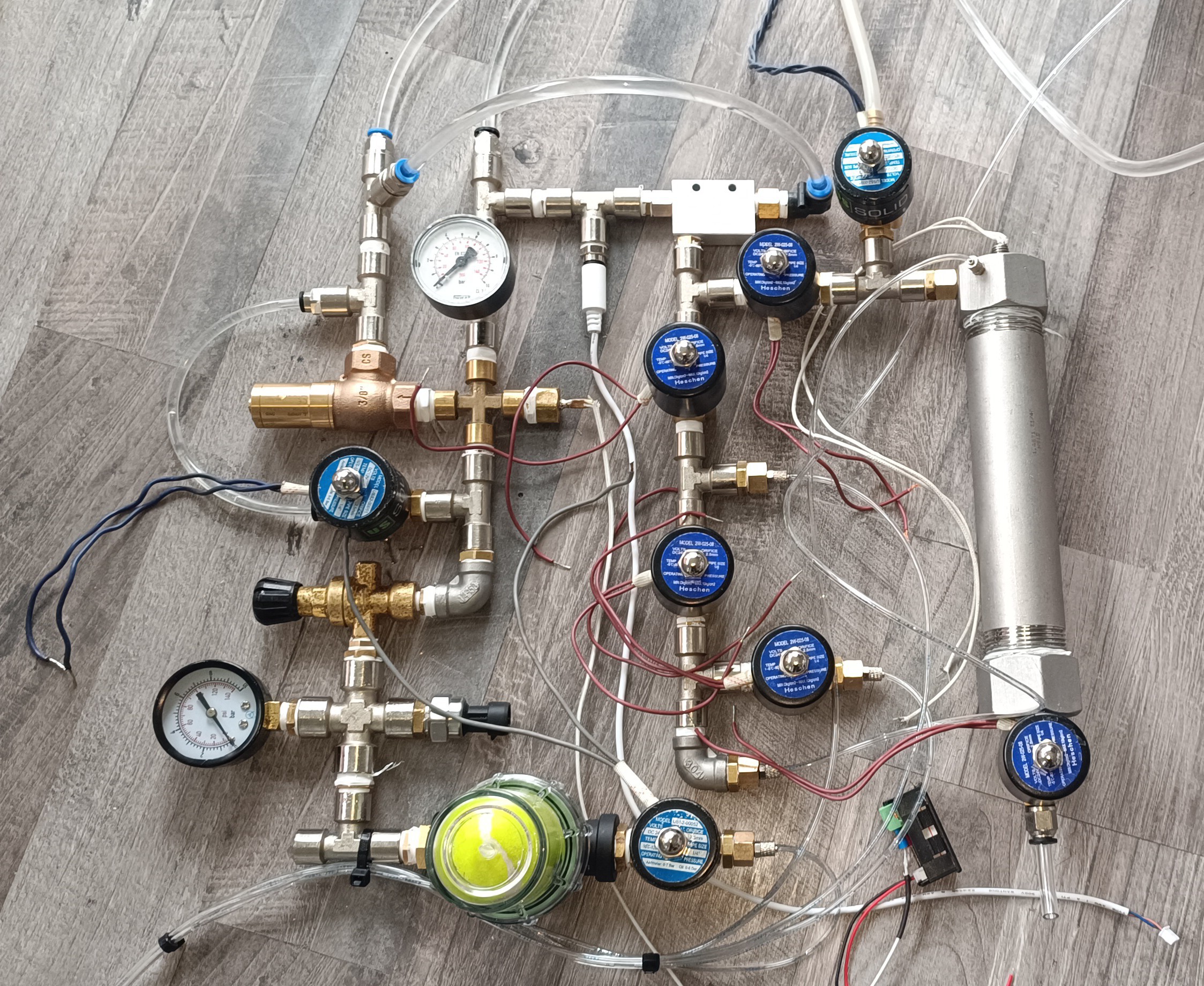
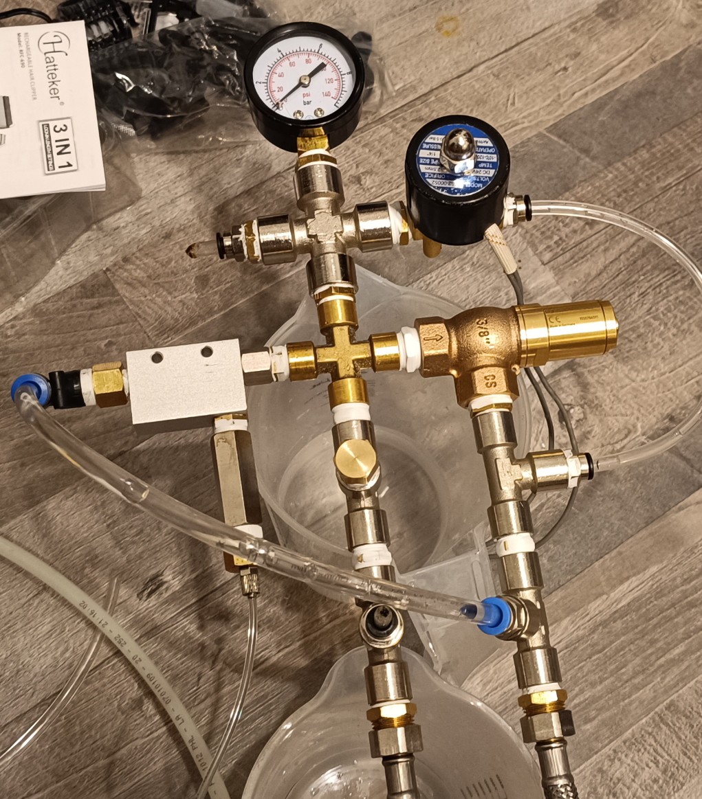
One note on the green thing at the bottom of the plumbing, the gauge, and the pressure regulator before it:
Since there are parts of the printer that apply varying loads on the system like the viscosimeter and especially the venturi pump, the pressure in the system is not perfectly stable. Because of that I used a higher pressure for the system pressure (50 psi) as for the ink stream pressure (40 psi) and added a beer filter with a small green tennis ball inside to the ink line for further stabilization. The air inside the tennis ball gets compressed by the ink and pushes against it. This way it acts like a capacitor and can stabilize the pressure of the ink stream.
The pond air pump I mentioned at the start of this build log is used to pressurize the MakeUp (Solvent) bottle. This is done to make it easier to feed the MakeUp into the vacuum line and it's also used for cleaning the Nozzle with MakeUp.
My current plan is to clean the nozzle at shutdown in an automatic process:
When the printer is turned off, first the ink to the nozzle is turned off. After enough time has passed to empty the gutter line, the vacuum to the gutter is turned off. Then the vacuum to the waste ink tank is turned on and the valve for cleaning the nozzle is opened to draw the ink from the nozzle into the waste ink tank. After some time has passed the vacuum to the waste ink tank gets turned off and the waste ink tank gets vented. Then the MakeUp valve gets turned on and a bit of pressurized MakeUp gets pushed through the nozzle to clean it. After some time the MakeUp valve gets turned off and the vacuum to the waste ink tank gets turned on for some time to dry the line from the nozzle to the waste ink tank.
When this is done, the nozzle should be clean and the ink pump + air pump should be turned off.
The waste ink tank also has a sensor to detect when it's full and a valve to drain it. I think I will keep the draining of the waste ink tank a manual operation to not accidentally spill the waste ink on the floor when no cup is placed under it.
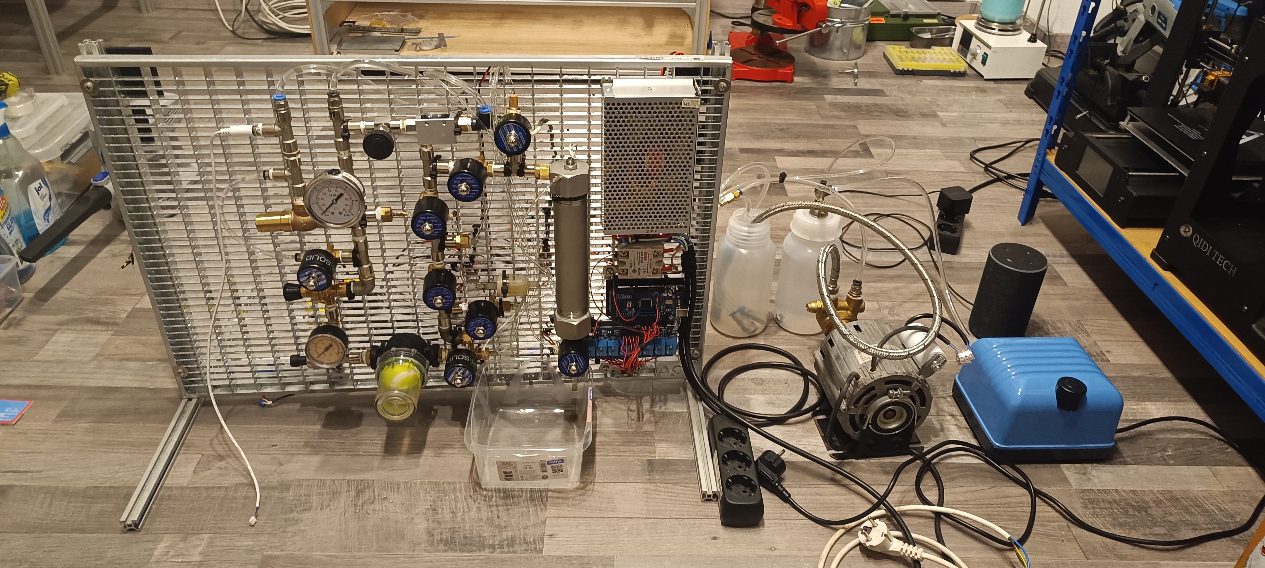
And this is it so far.
Currently, I have all valves and the waste ink sensor wired and the next thing is adding the viscosimeter back to the printer and connecting the temperature, conductivity, and pressure sensor to the Arduino.
When then everything is up and running, I can do a parts description and a building instruction for the fluid system of the new design.
I think this time I will keep the fluid system and the electronics for printing two separate things since the fluid system is mostly finished and there is still a lot of work to do on the printing electronics.
Thank you very much for your interest in my project :)
Discussions
Become a Hackaday.io Member
Create an account to leave a comment. Already have an account? Log In.