 Maakbaas
In this post and the next I will present the software that is running on my ESP32 soil moisture sensor. In this initial version of the software I focus on the parts that allow the sensor to work in standalone mode. This includes the push button, the status indicator and the actual sensor implementation. In the next and final post I will dive into the connectivity and WiFi functions.
The functions that the ESP32 soil moisture sensor should have are:
- Perform a capacitive measurement of the soil moisture level
- Periodically wake from deep sleep and check if the moisture level is above the threshold
- Flip the status indicator to red if the moisture level is too low and to green if the level is above the threshold
- Wake from deep sleep with push button to set the current moisture level as the new threshold
- Push the measurements to a database in the cloud using WiFi
- Create a smartphone notification when the plant needs water
The last two items will be implemented in the next post. The rest will be discussed below.
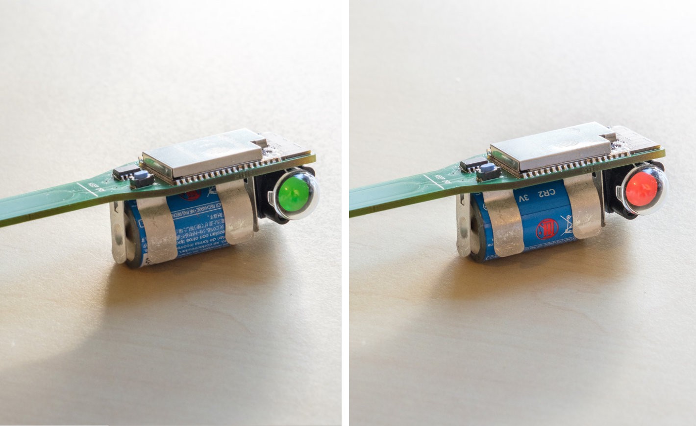
The two states of the status indicator.
Walking through the code
The basic principle of the code is that the ESP32 walks through a certain function once, and then goes to sleep again until the next wake event. Since I used the Arduino framework for this simple program, that means that all code is placed in the setup() function while the loop() function will remain empty.
The main architecture containing the deep sleep functionality is actually pretty simple and looks as follows:
#include <Arduino.h>
#include <Preferences.h>

Preferences preferences;

enum status_e{UNKNOWN, RED, GREEN};
RTC_DATA_ATTR uint16_t threshold = 0;
RTC_DATA_ATTR enum status_e status;
uint16_t output;

void setup() {
    // put your setup code here, to run once:
    pinMode(GPIO_NUM_13,OUTPUT);
    pinMode(GPIO_NUM_27,OUTPUT);
    pinMode(GPIO_NUM_26,INPUT_PULLUP);
    Serial.begin(115200);

    // perform a soil measurement
    do_measurement();

    esp_sleep_wakeup_cause_t wakeup_reason;
    wakeup_reason = esp_sleep_get_wakeup_cause();

    switch(wakeup_reason)
    {
        case ESP_SLEEP_WAKEUP_EXT0 :
            handle_buttonpress();
            break;
        case ESP_SLEEP_WAKEUP_TIMER :
            handle_timer();
            break;
        default :
            handle_firstwake();
            break;
    }

    esp_sleep_enable_ext0_wakeup(GPIO_NUM_26, 0);
    esp_sleep_enable_timer_wakeup(1000000 * 60 * 60);

    esp_deep_sleep_start();
}

void loop() {}
In the setup function, first the GPIO are configured. Pin 13 drives the H-bridge to switch the status indicator to red, pin 27 to green, and pin 26 is the push button. For this the internal pullup of the ESP32 is used.
Next, the function esp_sleep_get_wakeup_cause is used to determine what caused the ESP32 to wake up. There are three possibilities which are detected in a switch statement. The three possibilities are:
- Wake up from deep sleep by pushing the button
- Wake up from deep sleep because of the timer
- First startup of the device
These functions will be discussed in the next sections. Finally the deep sleep function is set up to wake from the button or by means of a timer.
do_measurement()
Reading the sensor using the ESP32 touch functions happens here as was already discussed in the previous post:
touch_pad_init();
touch_pad_set_voltage(TOUCH_HVOLT_2V4, TOUCH_LVOLT_0V5, TOUCH_HVOLT_ATTEN_1V);
touch_pad_config(TOUCH_PAD_NUM2, 0);

//do measurement
touch_pad_read(TOUCH_PAD_NUM2,&output);
handle_buttonpress()
When the button is pressed first a delay is placed to debounce the button. Otherwise the function might complete and retrigger multiple times before the button is released. After this, the threshold is updated with the current sensor value output subtracted by 5 to have some margin. The new threshold is stored into NVM by using the ESP32 preferences functions. Finally the status indicator is switched to red if it was not yet red before.
//debounce button press
delay(1000);

//set threshold to current value
threshold = output - 5;
preferences.begin("nvm", false);
preferences.putUShort("threshold",threshold);
preferences.end();

if (status!=RED)
{
    //set to red
    digitalWrite(GPIO_NUM_13,HIGH);
    delay(500);
    digitalWrite(GPIO_NUM_13,LOW);
}
handle_timer()
The timer function is even simpler. All it does is switch the status indicator where needed based on the current sensor reading.
//check the sensor
if (output > threshold && status!=RED)
{
    //set to red
    digitalWrite(GPIO_NUM_13,HIGH);
    delay(500);
    digitalWrite(GPIO_NUM_13,LOW);
} else if (output <= threshold && status!=GREEN)  {
    //set to green
    digitalWrite(GPIO_NUM_27,HIGH);
    delay(500);
    digitalWrite(GPIO_NUM_27,LOW);
}
handle_firstwake()
The final function handles initialization when the device is first powered on. In this case the status indicator is not changed, because it is quite likely that the device is not placed in the soil when it is first powered on. During this first initialization the threshold is read from the NVM and stored in a local variable. This local variable has theRTC_DATA_ATTR attribute, which means that it will be stored in such a way that it is persistent during deep sleep. This is not the case for normal memory.
//read EEPROM
preferences.begin("nvm", true);
threshold = preferences.getUShort("threshold");
preferences.end();
Next steps
In the next and final post I will present the connectivity and WiFi functions for this device which will enable it to push measurements and notifications to the cloud.
Discussions
Become a Hackaday.io Member
Create an account to leave a comment. Already have an account? Log In.