 Michael Gardi
Background
If you have been following Hackaday for a while, you will have seen on numerous occasions the KENBAK-1, regarded by many as the first commercial personal computer. Ten years ago Mark Wilson introduced KENBAK-uino, a reproduction running in emulation on an ATmega328. In 2016 Brian Benchoff posted a great writeup about John Blankenbaker KENBAK-1's creator. For a first hand account of the KENBAK-1 story you should really have a look at John Blakenbaker's own KENBAK-1 Computer site.
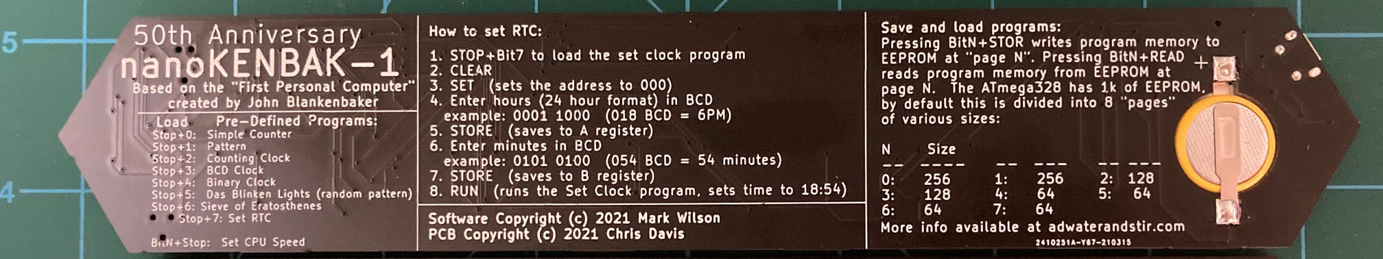
For a while you could purchase a full size KENBAK-1 Reproduction Kit, with a PCB, power supply, authentic metal case, 132 standard series TTL logic ICs as the CPU / process control logic (that's right no microprocessor) and two 1024 bit shift registers for memory. Unfortunately this option is no longer available, but based on Mark Wilson's code Adwater & Stir offers a ruler sized nanoKENBAK-1, a half size µKENBAK-1 kit, and will soon be offering a full sized kit as well. In addition you can find KENBAK-1 emulators online like this one.
Motivation
So with all of this rightly deserved KENBAK-1 love out there, why am I creating yet another KENBAK-1 emulator? The flip answer might be that I want to and I can, but that's not all of it. While all of the wonderful reproductions out there emulate the original to a tee and give a true KENBAK-1 experience, and even have some addition features like built in programs, at the end of the day you are still in many cases hand translating machine instructions and keying them in via the front panel buttons one step at a time. And when something goes wrong, while you can step through your program one instruction at a time you only have visibility into one thing at a time on the front panel display, the instruction or a memory/register address. It gets old pretty fast.
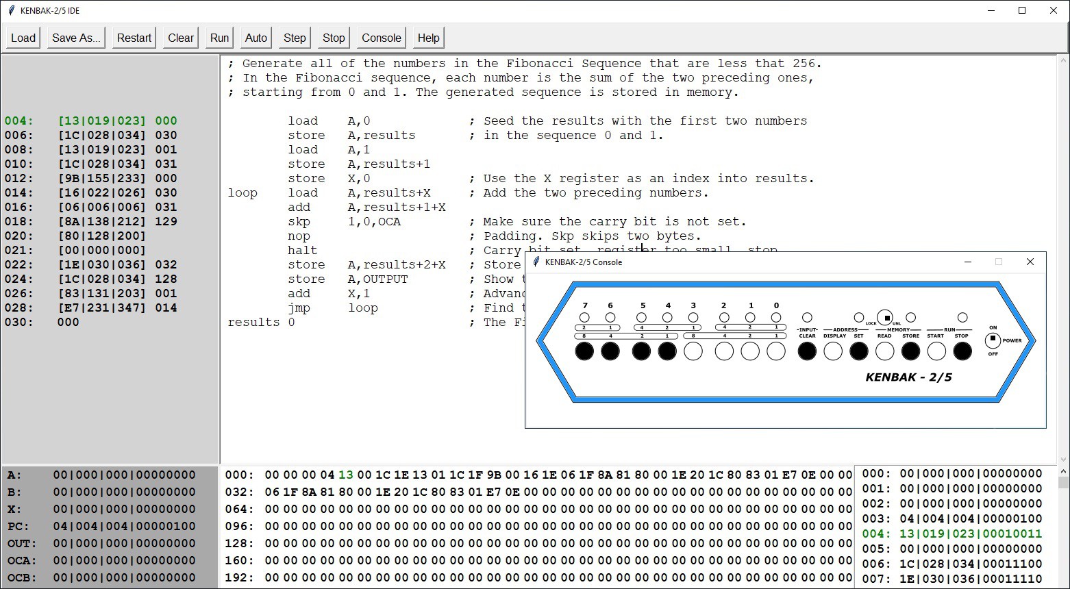
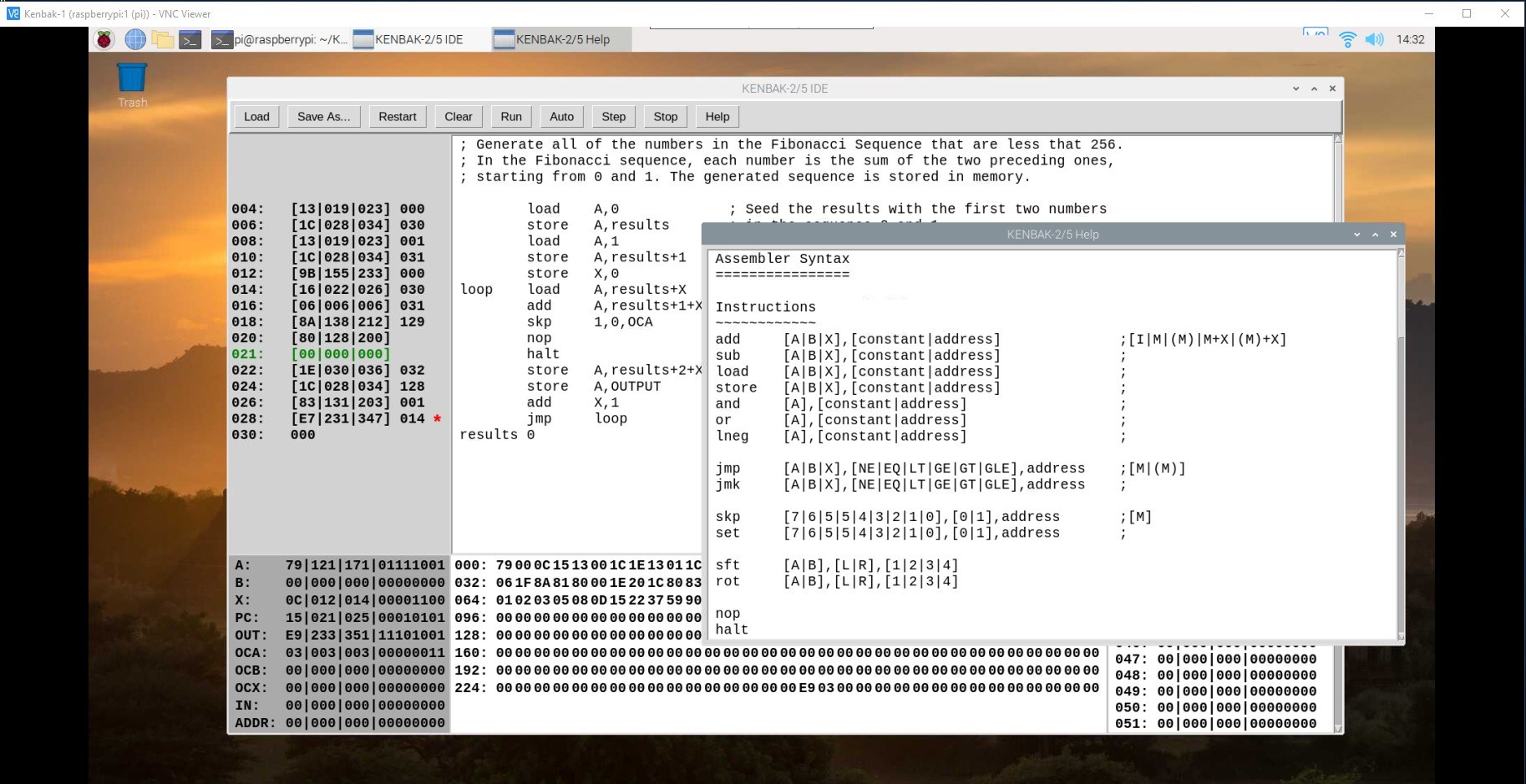
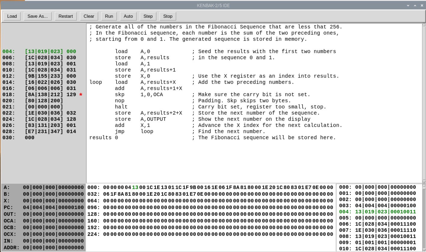
Where I think I can add some value is to integrate the machine code Emulator with an Assembler and a Debugger. You will still be able to fire up my KENBAK-2/5 console to key and run your programs in native mode via the front panel. In addition you will be able to open an integrated development environment, enter in a KENBAK-1 program via assembly language and run said program using the actual console. Similarly you will be able to step through your assembly code, set break points, and observe memory and register contents as you do.
My other motivation for this project is that I really wanted to do a deep dive on this machine. When I looked at the Programming Reference Manual I was very impressed with the machine architecture and the instruction set. I mean an Indirect Indexed addressing mode on a machine built with logic chips. So cool.
Design Considerations
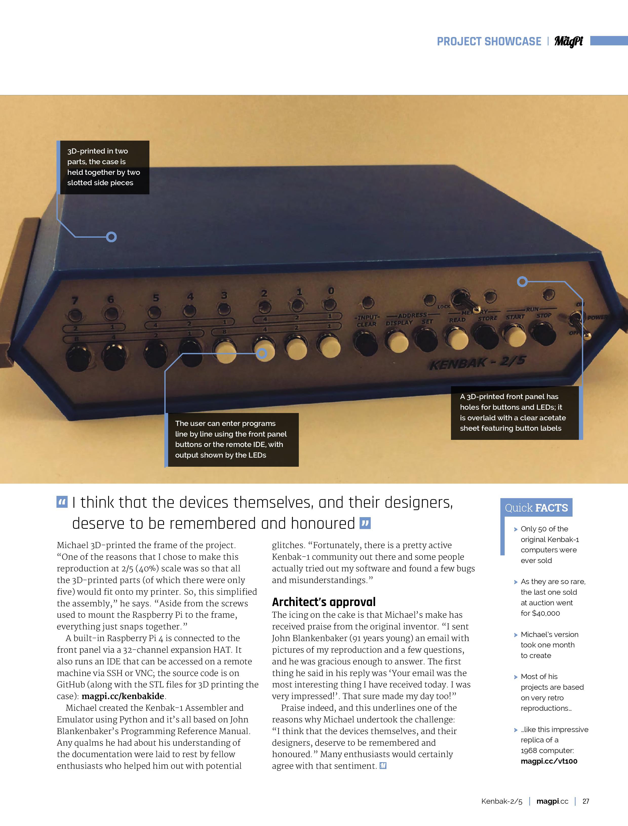
- The console itself will be rendered at 2:5 scale (hence the name KENBAK-2/5). This is primarily so that all of the parts will fit onto the print bed of my Prusa MK3S.
- A built in Raspberry Pi 4 will be connected to the front panel via a 32 channel port expander. In addition to running the KENBAK-1 Emulator, the extra horse power of the Pi will be required to run the "integrated development environment" (IDE).
- The IDE will be accessed by connecting a display, keyboard, and mouse to the console's PI 4 itself or via VNC (preferred).
- The Emulator, Assembler, and Debugger will be written in Python.
Hardware Required
In addition to the 3D printed parts you will require the following:
- 1 Raspberry Pi 4
- 1 MCP23017 32 Channel I/O Expansion HAT (https://www.buyapi.ca/product/mcp23017-hat-32-channel-io-expansion-hat/)
- 12 3mm LEDs (8 white and 4 yellow)
- 2 Toggle switches (KINYOOO SPDT Mini Toggle, On/On 3 Pins 2 Position - Amazon)
- 15 Push Button Switches (Mini 7mm Momentary (Off-ON) Push Button - Amazon - 8 black and 7 white)
- Hook up wire. I used 22 AWG.
- Female headers with 2.54 mm spacing.
Making the Console
The KENBAL-2/5 console has a 3D printed frame and uses panel mount components....
Read more »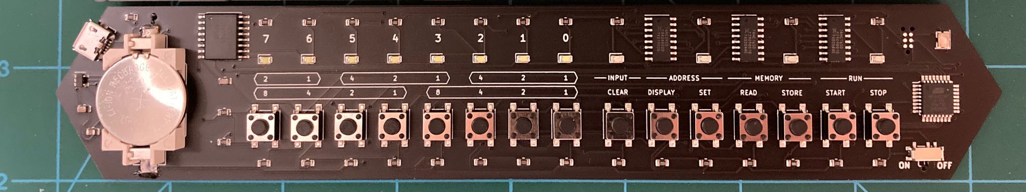


 TwinkleTwinkie


 Kevin Claytor
Finally a 2:5 Scale KENBAK-1 project with lots of interesting features.
https://www.marriagecounselingoffortworth.com