 Joe Wingbermuehle
I started out by looking into RTL as a possible substitute for NMOS for the Q2 as a way to speed it up. In the end, I think NMOS is probably the best bet:
- RTL requires base resistors, which greatly increases component count.
- An RTL gate always draws power (when low, just like NMOS, but also when high, through all output gates). This makes it even more difficult to get a low-power (sub-500mA) design, which is important since I want to be able to run the Q2 off of a USB adapter.
- RTL really only works well with NOR gates, which makes the logic slightly more complex (though in reality, NMOS works better with NOR gates too).
From my experiments, an RTL design can easily go faster, but given the power constraint, it isn't a clear win.
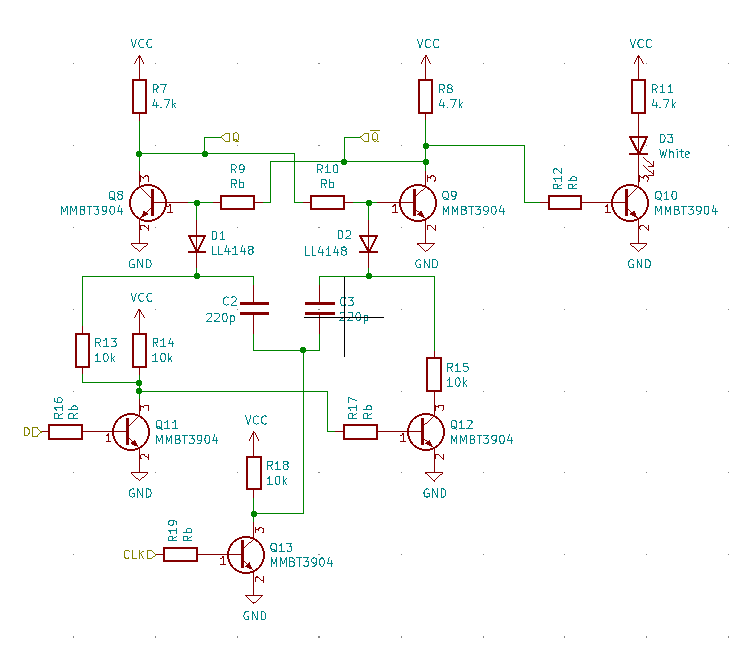
Despite this outcome, the RTL investigation caused me to look into alternative flip-flop designs. Given the 46 flip-flops in Q2, the simple edge-triggered design I had in NMOS wasn't going to cut it in RTL. So I started looking into a pulse-triggered flip-flop (shown below). This design is kind of neat because it uses so few transistors. Unfortunately, it doesn't seem to translate easily into NMOS, and it's somewhat picky about component values as you increase the clock frequency (not to mention the high component count).
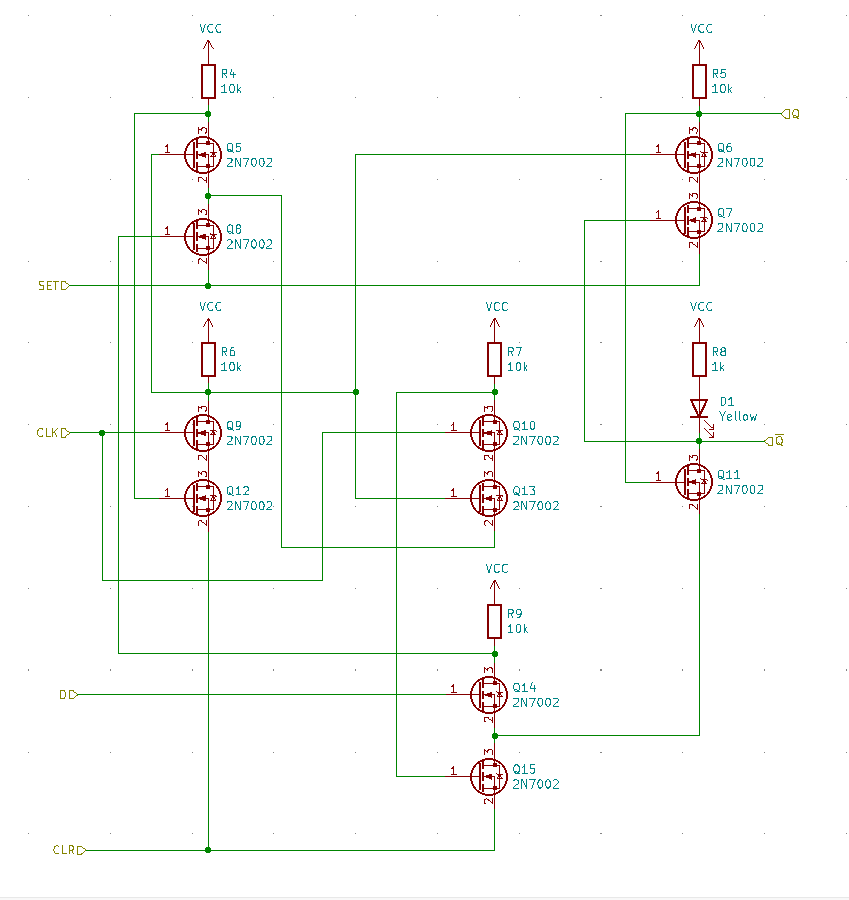
The current Q2 flip-flop design is shown below (without the LED section). It's basically the classic positive-edge triggered flip-flop from NAND gates with set and reset.
Using 14 transistors, 7 resistors, and 1 LED each, these DFFs make up most of the Q2 by component count and area. So saving even one component would be a good savings.
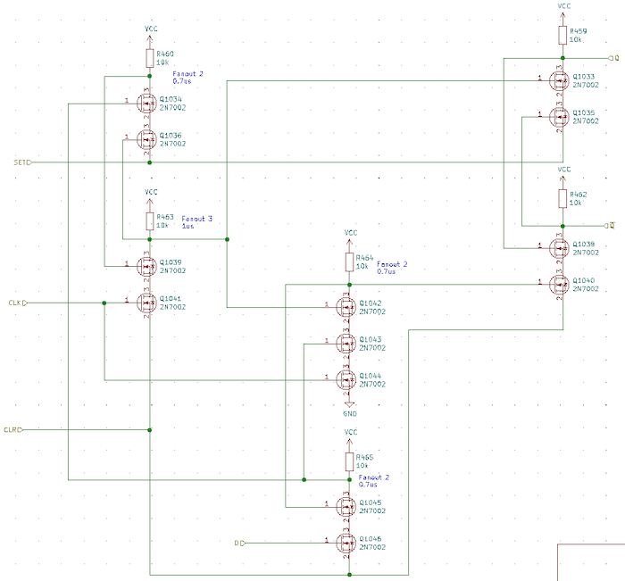
A new design is shown below. By re-arragining some inputs, it's possible to "share" a couple of transistors. Also, by switching to an LED with a low voltage drop, we can save a transistor and resistor, using the LED as part of the pull-up. We're left with a positive-edge triggered D-flip-flop with set and reset, using 11 transistors (all the same type), 6 resistors, and 1 LED.
The smaller flip-flop design will save 138 transistors and 46 resistors. In addition, the pull-up on the inverted output is actually faster due to the low resistance to power the LED.
Discussions
Become a Hackaday.io Member
Create an account to leave a comment. Already have an account? Log In.