 jörg postert
This is my first project to make public. I love neon filled tubes, because of their warm glow.
Sure, I've already build some clocks using nixie tubes, but this russian 1990´s MC6205 is very special and it catches my interest.
The MC6205 uses a IGPP-100/100 (GIP-10000), which is a 10000 pixel plasma tube. Technically similar to Burroughs SelfScan Plasma tubes.
It has been used in USSR CNC systems, programmable logic controllers and bill counters.
Unfortunately, after I powered it up the first time, I realized, that it has only a limited set of 96 characters. Most in cyrillic and that rendered it nearly unusable for me.
But hey, in the package, there was the solution for it. Some very detailed schematics.
It took some time, to re-engineer the used eprom's character-set definitions, which was/is really weird.
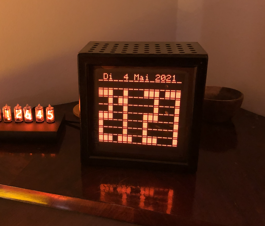
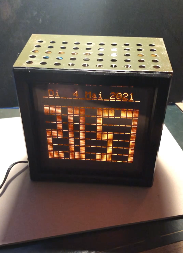
So, what you will find in this project is a MC6205, which works with an expanded set of 128 characters based on western ISO-Latin-1 and connection to the internet via WLAN.
Obstacles:
- main obstacle, you need a customized ROM (EEPROM 2816 or EPROM 2716, 2732)
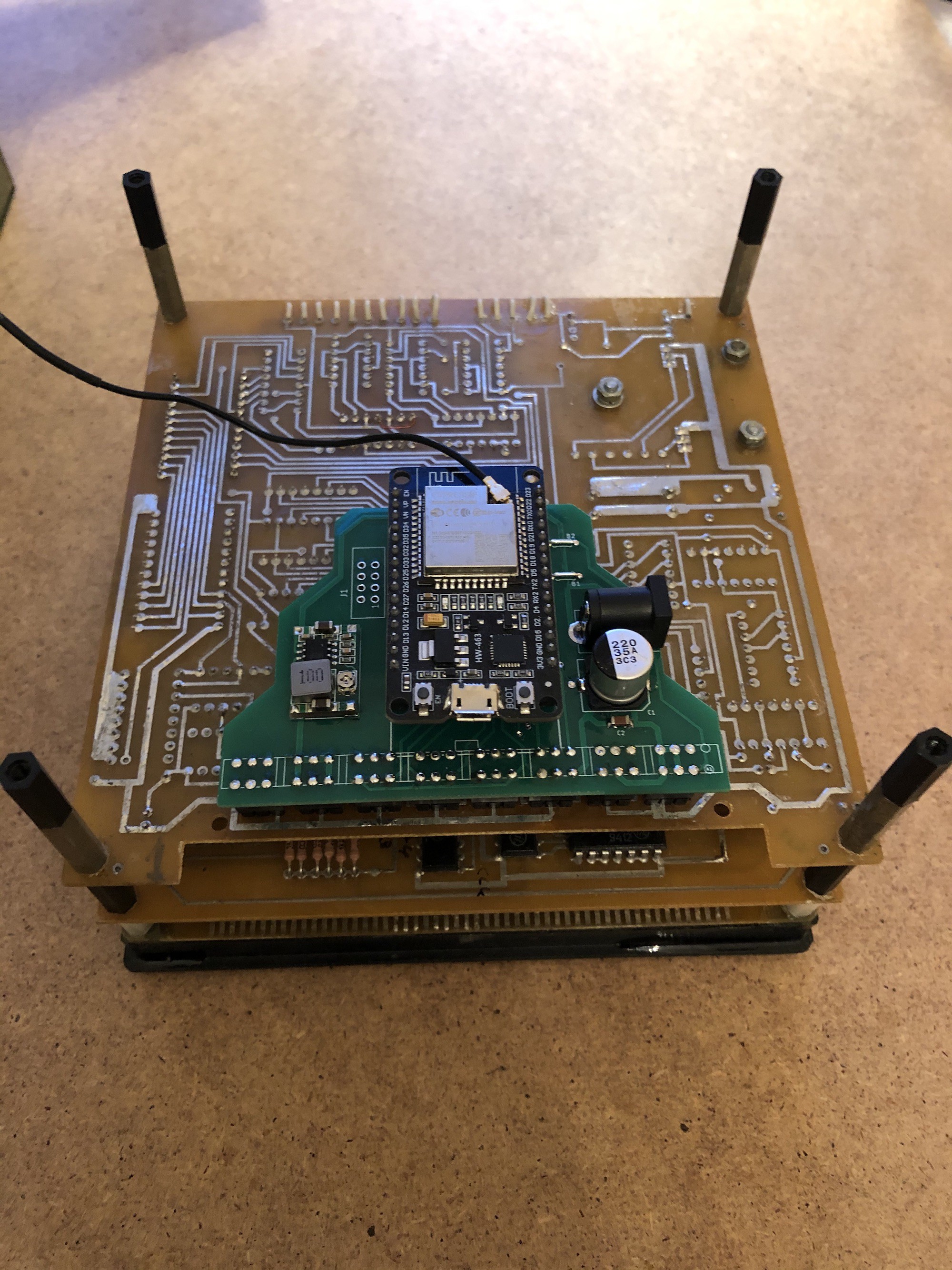
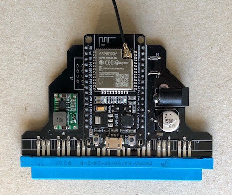
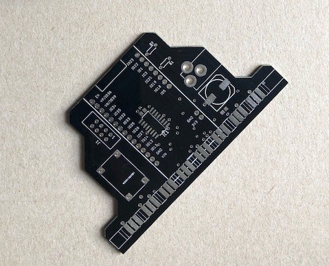
- further you need soldering experience, a PCB with the driver logic and an e(e)prommer, or ask me for the PCB/PROM
What you get:
- Some really nice days of hardware and software hacking
- a functional basic weatherstation (based on data from openweathermap.org - get your API key from there)
- NTP-clock
- Terminal, where you can display your text via the internet
- ESP32 Arduino knowhow
Power consumption:
Using a standard 12V 1A wall mount powersupply and usage of the MP2307 the average power consumption is about 90mA.
Hardware modification:
How does the hardware change work to get the missing data bit and the advanced charset:
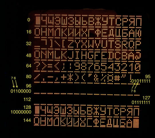
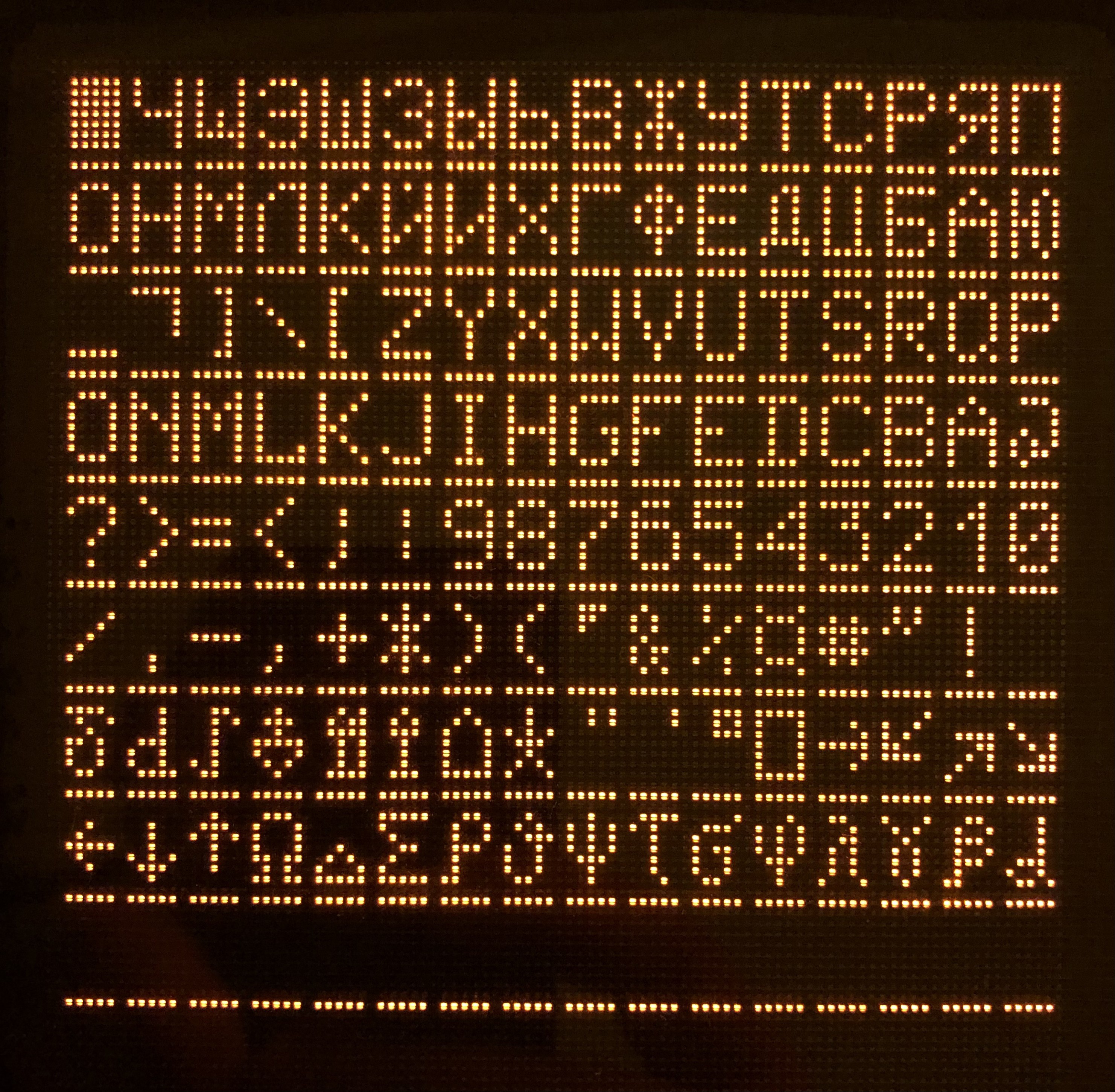
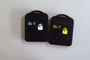
This is the picture of the original charset with no hardware change. Look at Bit 6 und 7 (arrows
And the picture with the changed hardware:
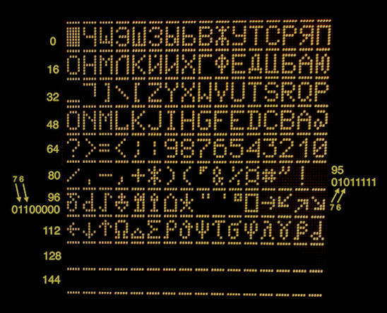
So, what make the difference to see the hidden charset this time.
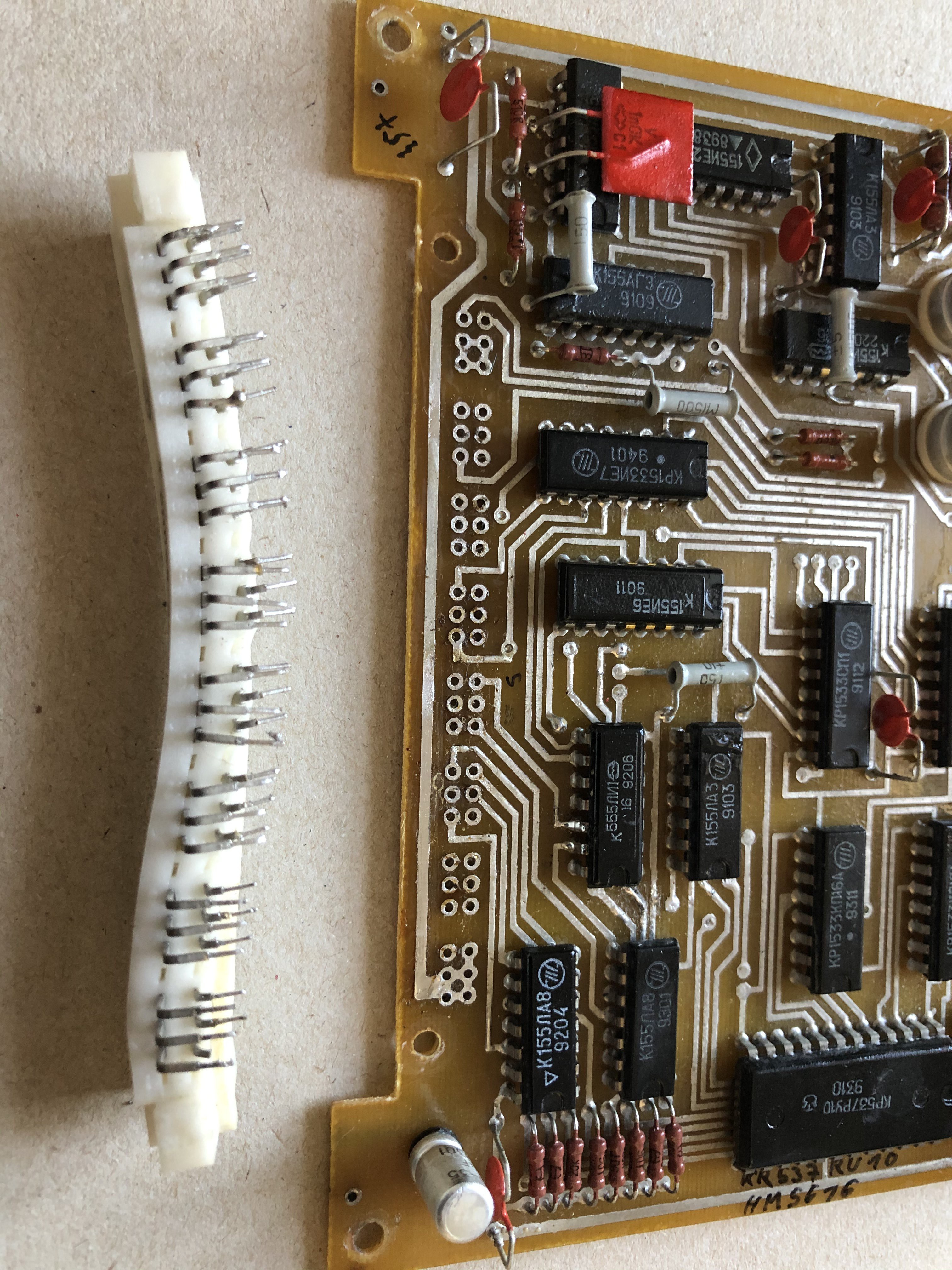
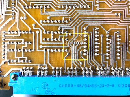
Let's take a look at the schematics:
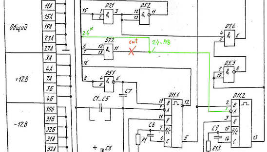
The point of interest is gate D7.2, an AND gate (к155ли1==7408). As you can see, trace 6 and 7 are connected to pin 12 and 13, the inputs of the AND gate. Trace 6 and 7 corresponds to bit 6 (18B) and 7 (24B).
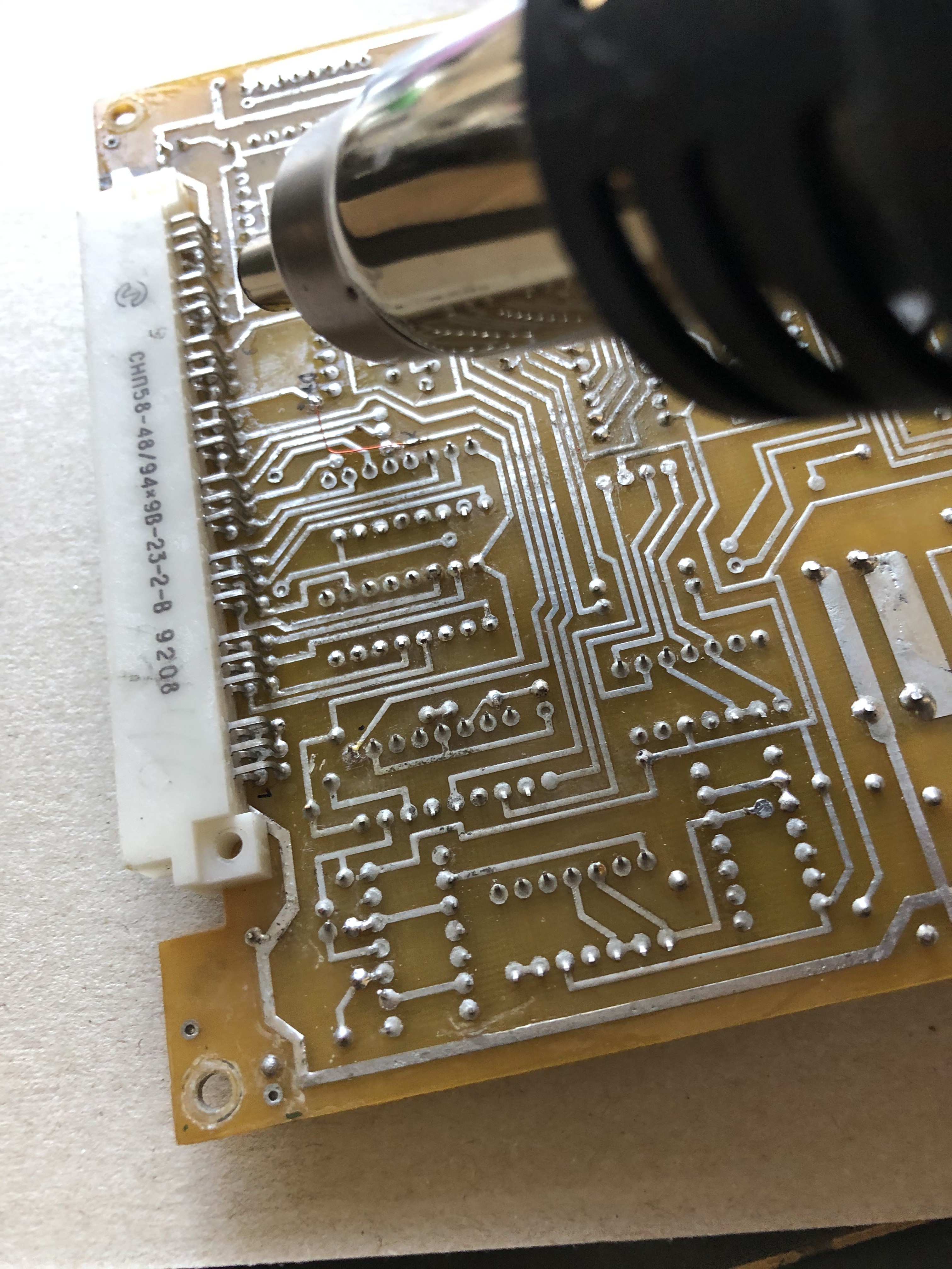
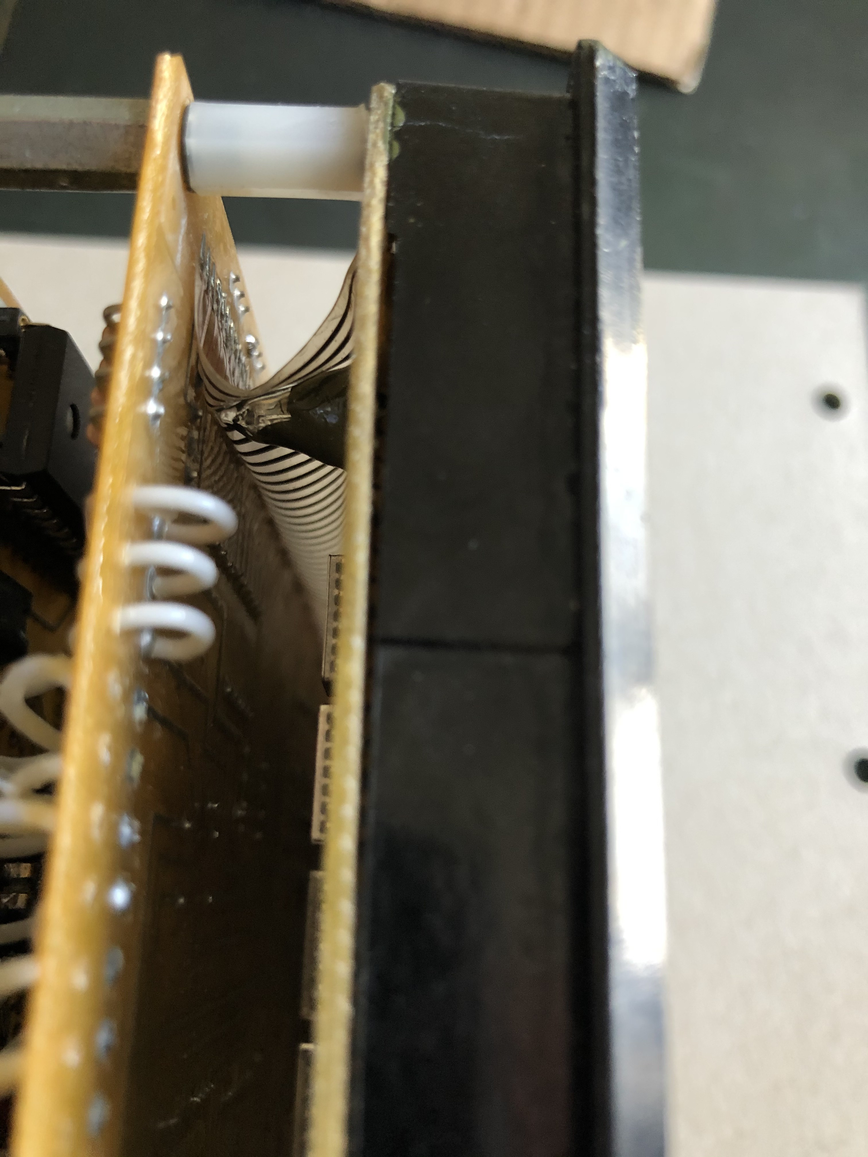
With trial and error plus schematics and knowledge of the ROM's data this leads to success. Cutting the output of the AND gate and connecting the open trace to A8 (20A) gave me the missing characters.
But in fact it is a modified trigger of the WR mimic to the onboard RAM. Just follow the green trace and the ouput traces of the corresponding gates. (Full schematics in the files section)
Please keep in mind, that the data and address bus are connected together via the driver PCB.
But why did the hardware designer do that, mystique...
So, if you have a different schematics, layout, then look at those bits and the corresponding AND/NAND gates.


 dsl
dsl
 marcoA152
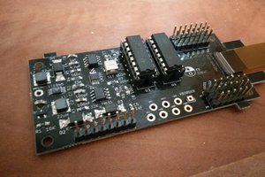
 sapir
sapir
Fantastic project !!