 Manuel Tosone
Extracting LUTs from embedded FLASH
Before going too deep into designing custom LUTs from scratch, I thought it would be interesting to see how the stock ones look like. We have already seen that the LUTs are stored on a FLASH memory that's soldered directly on the FLEX cable. The package is a bit of a pain to work with, it's an 8 pin USON with a 0.5 mm pin pitch. Fortunately, the controller has a mode where the internal SPI master is bypassed, and the memory can be accessed via the main SPI bus. To make this work, two more pins have to be connected, MFCSB and FMSDO, they are respectively the memory chip select and data out. The breakout board doesn't provide connections for them, some modification is needed. Conveniently, the level translator has two unused lines that we can use to interface with the microcontroller.

I used magnet wire to make the connections, secured them in place with hot glue. The two extra lines come out from the bottom header. The center conductor is ground. Originally I tried without it, but it didn't work. With 30 cm of cable, only one ground wasn't enough to run a 1Mb SPI.

I'm using an STM32F4 Discovery as my development platform. After connecting the display, I wrote some code to spit out the FLASH content over the serial port. From the manufacture and device ID, I determined that the memory is a Winbound 2Mbit W25X20CL. With PuTTY running in log mode on my desktop, I was able to extract the contents of the memory. All the code that I've used is on GitHub, here is a link to the memory dump.
Flash memory content
Waveshare recently released more information about the controller. The right one is the SPD1656. On page 15 of the datasheet, there is the complete memory layout. Besides LUTs, there are also voltages and framerates for each temperature range. In this particular case, they are the same for every temperature, but they don't need to be. The full listing can be found here.
------------------------------------------
 VCOM DC OFFSET SAME FOR ALL TEMPERATURES
------------------------------------------
VCM_DC = 1.050000e+00 V

---------------------------------------------------
 VOLTAGES AND FRAMERATE FOR DIFFERENT TEMPERATURES
---------------------------------------------------
T0 TEMP < 18°C
VSHC_LVL   =   10 V
VSLC_LVL   =  -10 V
LVL2_EN    =    0
VSLC_LVL2  =    3 V
FRAME RATE =   50 Hz

T1 18°C <= TEMP < 21°C
VSHC_LVL   =   10 V
VSLC_LVL   =  -10 V
LVL2_EN    =    0
VSLC_LVL2  =    3 V
FRAME RATE =   50 Hz

...
From LUTs to waveforms
Now I want to explain how the waveforms are constructed. Taking as an example the previously measured VCOM voltage, we can see the correspondence between the trace and what's inside the LUT.

More LUTs
Besides VCOM, there are 8 more waveforms one for each color. I made a couple of MATLAB scripts that can plot them for us. Since the display cares only about the difference in voltage between the common electrode and the pixel electrodes, the following plots represent the difference between VCOM and the color waveform. The waveforms are positive when the voltage on the common electrode is higher than that of the pixel electrodes.
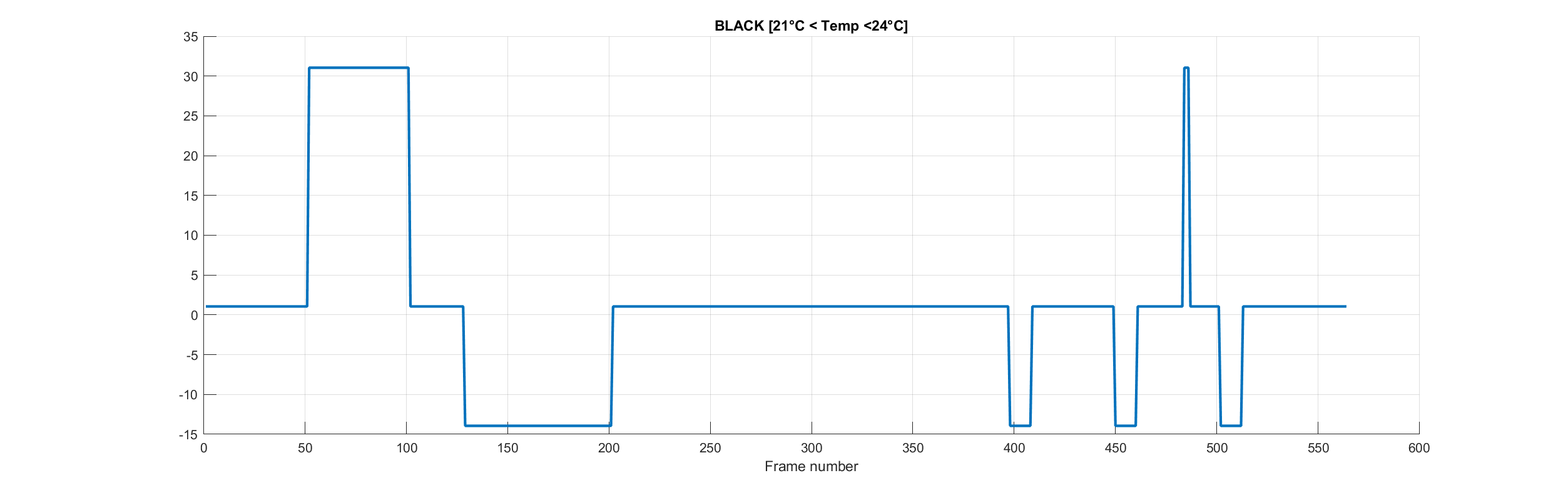
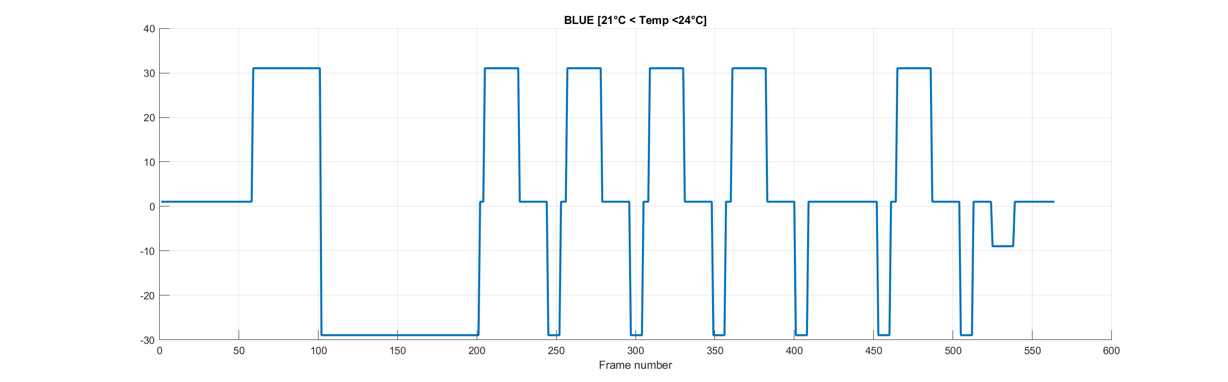
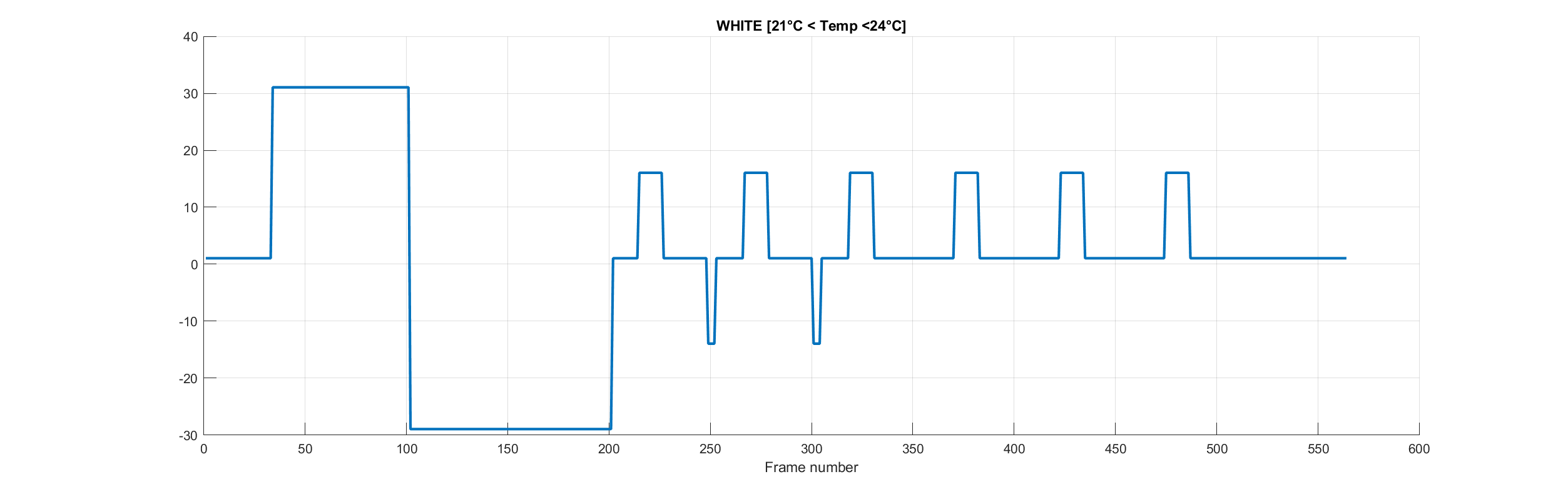
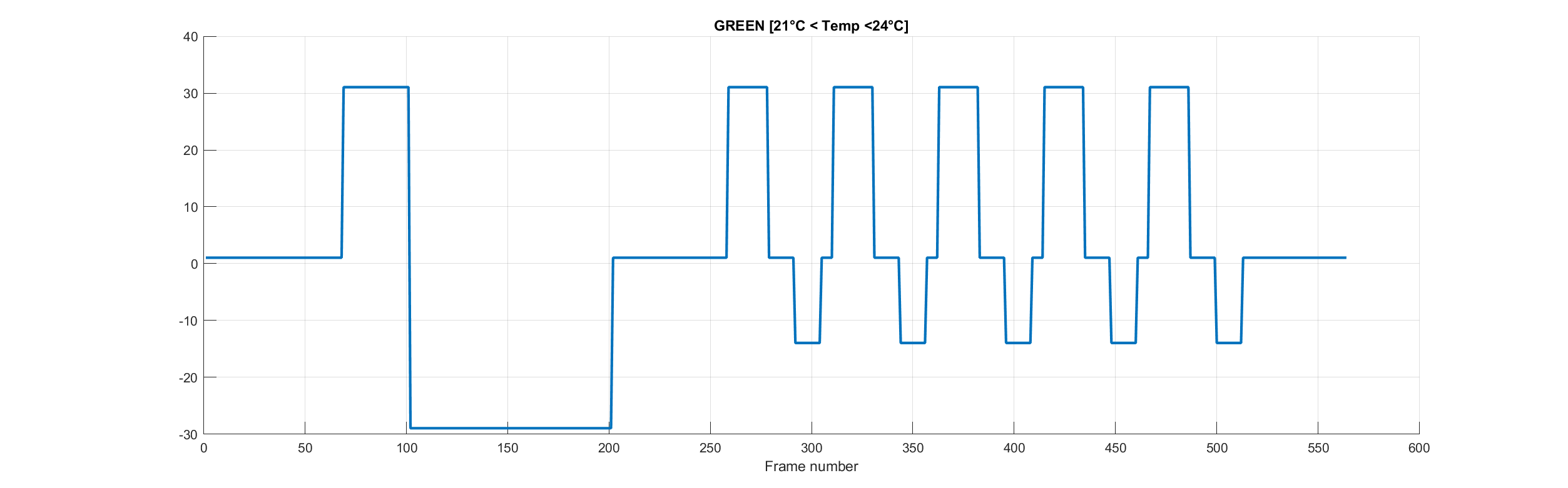
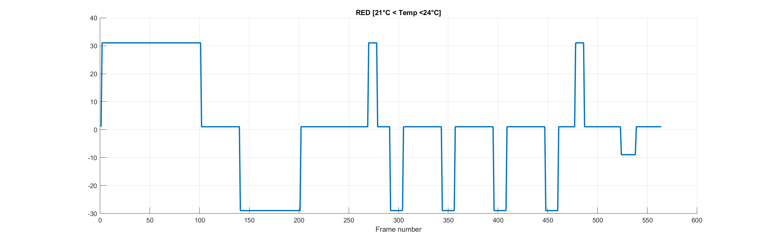
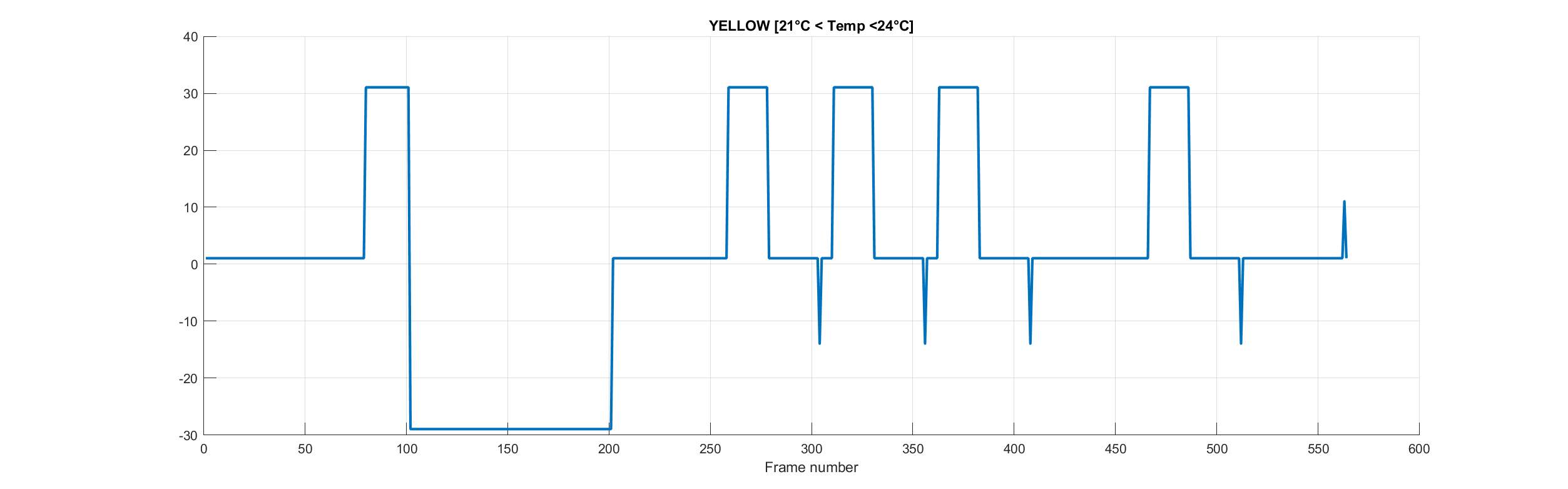
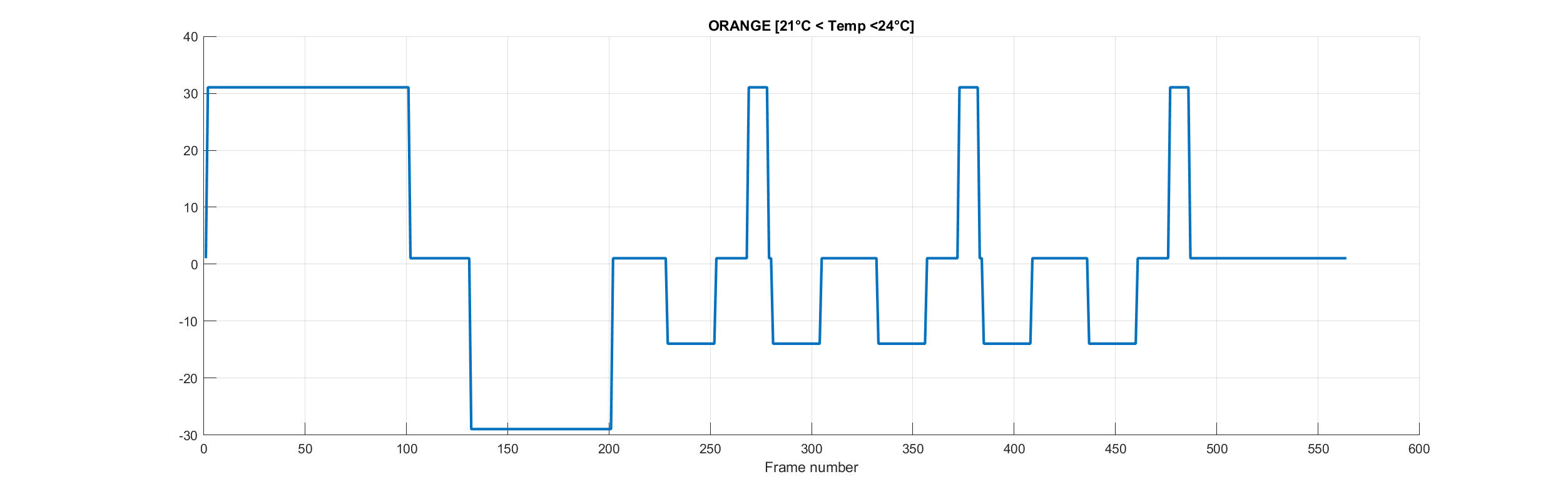
The display supports 10 temperature ranges. Here I show only the waveforms for the range 21°C to 24°C the others can be found on GitHub.
Black waveform, 21°C to 24°C temperature range.
Blue waveform, 21°C to 24°C temperature range.
White waveform, 21°C to 24°C temperature range.
Green waveform, 21°C to 24°C temperature range.
Red waveform, 21°C to 24°C temperature range.
Yellow waveform, 21°C to 24°C temperature range.
Orange waveform, 21°C to 24°C temperature range.
Clean waveform, 21°C to 24°C temperature range.

Conclusion
What can we derive from this?
First of all, VCOM has a DC offset. Not sure why, I think it's there to bias the TFT matrix. Ignoring that, all the waveforms average to 0, that's important to not damage the display.
Second, the waveforms seem to be made up of two parts. The first is like a DC balance plus it leaves the display in a known state. The second is where the colors are developed.
If you see something else please leave a comment, we need to master this thing :)
EDIT 10/05/2021:
Modified title for the first 4 plots. Playing around with the display I found a quirk in the controller. If you look at the order in which the LUTs are stored in FLASH and what registers are loaded, you see that for the first 4 LUTs, the pixel value doesn't correspond.


Discussions
Become a Hackaday.io Member
Create an account to leave a comment. Already have an account? Log In.
In the conclusion you mention "all the waveforms average to 0, that's important to not damage the display". Does that warning come from documentation somewhere, or is it something common to e-paper displays?
I ask because I'm attempting to make a driver with fast refresh, that keeps track of the previous display state to just apply what's needed to change a pixel from the current color to a target color. If I built custom LUTs that didn't average to 0, but made sure to do a proper full screen refresh every few updates, do you think that would still damage the display? If so, what about keeping track of a "voltage debt" to average each pixel back to zero before doing a full refresh?
Thank you for publishing all this, it's extremely informative.
Are you sure? yes | no