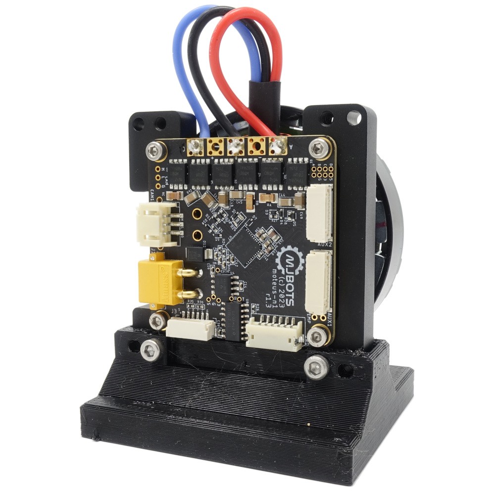
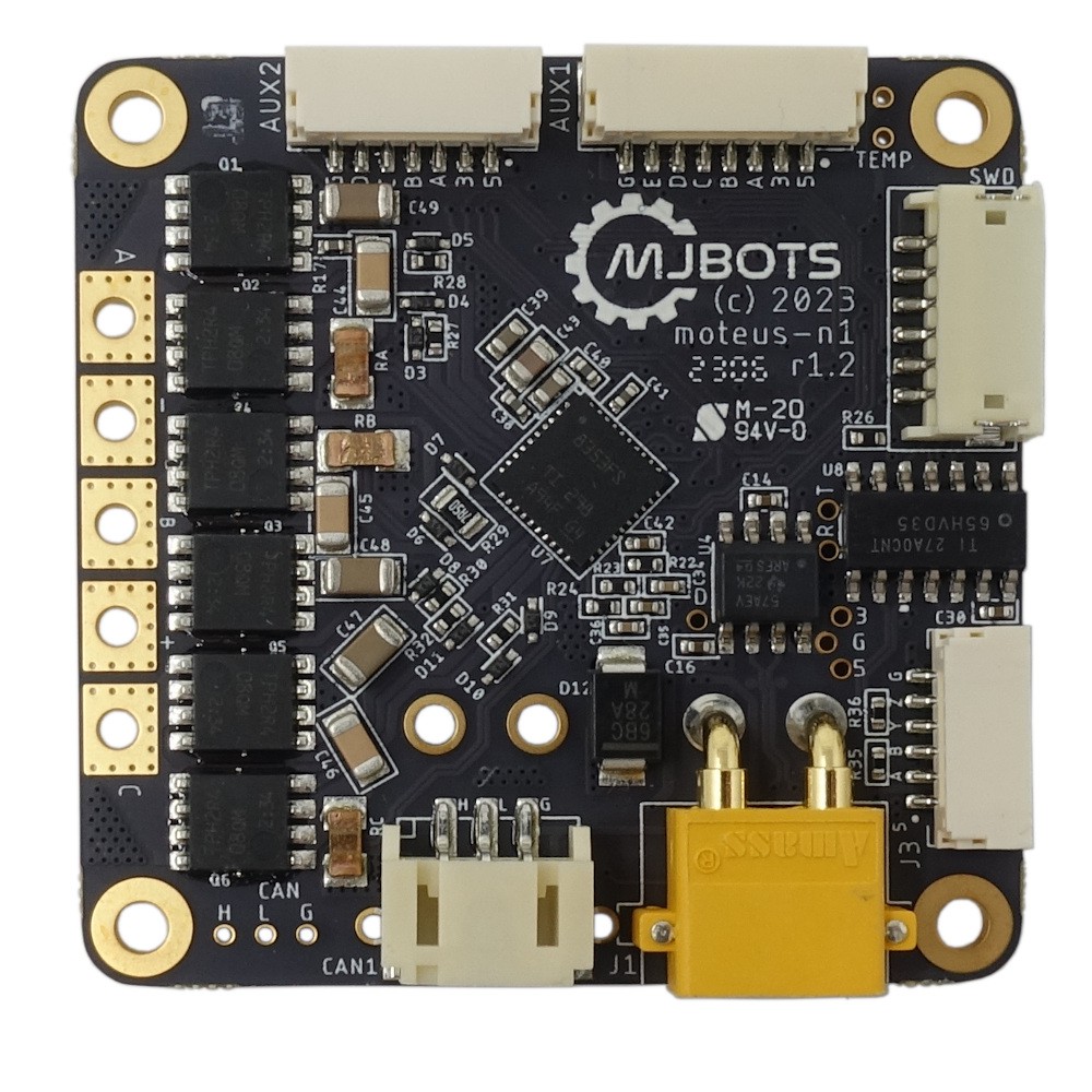
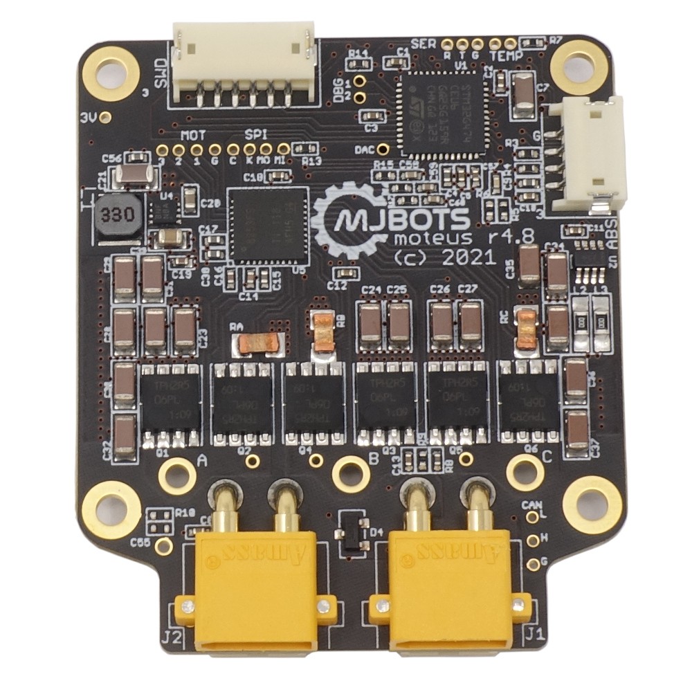
• Arduino library for moteus

    Josh Pieper02/12/2024 at 14:44 0 comments

    In the spirit of the C++ bindings released last summer (and using a lot of the same code), there is now an official Arduino library to command and monitor any moteus controller!  To get started, just search for "moteus" in the Arduino library manager, install it, and look through one of the examples.

    The biggest caveat is that a desktop CAN-FD adapter is still required to calibrate the moteus initially.  Thus you can't get away with only an Arduino, but it is a solution for deployment.

    Check out the video showing it in operation here:

  • moteus C++ bindings

    Josh Pieper09/19/2023 at 13:11 0 comments

    moteus has had python bindings for a long time, and had a half-completed CAN parser library in the pi3hat repo, but there has never been great support for developing in C++.  No longer!

    Now, in the mjbots/moteus repository, there are C++ bindings that can be used for applications that allows full control over all of the capabilities of any moteus controller using a fdcanusb, socketcan, (or the pi3hat).  It is modeled after the python library, so simple cases look about the same:

    #include "moteus.h"
    
    // ....
    
    mjbots::moteus::Controller c;
    
    mjbots::moteus::PositionMode::Command command;
    command.position = 0.5;
    const auto maybe_result = c.SetPosition(command);
    std::cout << "Position: " << (maybe_result ? maybe_result->values.position : 0.0) << "\n";

     I've got two videos showing first how to use it in a 1 controller example, and second in an example with 2 controllers at the same time:

  • moteus-n1 semi-automated test fixture

    Josh Pieper07/15/2023 at 11:22 0 comments

    Now that the moteus-n1 is finally released, I've documented the test fixture I made to perform end-of-line testing on it.  Most DIY test fixtures are clamshell affairs that can probe the top and bottom of the board.  This is 5 sided, probing top and bottom, as well as 3 of the 4 sides in order to test the right angle connectors.

    I've got a longer writeup showing how all the mechanics work up here: https://jpieper.com/2023/07/15/5-side-pcb-test-fixture/

  • moteus-n1 now available at mjbots.com

    Josh Pieper07/11/2023 at 11:39 0 comments

    After a successful beta release, the moteus-n1 is now generally available at mjbots.com!

  • moteus-n1 beta

    Josh Pieper03/13/2023 at 17:17 0 comments

    I'm excited to announce beta availability of a new controller in the moteus lineup, the moteus-n1!  This new version is in addition to the existing moteus r4.11, but adds more capabilities, a smaller mechanical profile, and has an increased maximum voltage of 54V.

    External Peripherals

    The biggest new feature in this new version is improved external peripheral support.  The r4.11 had an "aux2" connector with exactly 2 pins.  The moteus-n1 has 2 external connectors, aux1 and aux2.  Aux1 has 5 pins and aux2 has 4 pins.  Each of those can support any of SPI, I2C, ADC, UART, GPIO, Quadrature, or Hall sensors.

    There are many more exposed 5V tolerant inputs.  All 4 user pins on aux2 are capable of 5V, which means most hall effect sensors can be connected with no additional level shifters required.

    Both connectors also provide 3.3V and 5V power (up to 100mA for each rail) to power external peripherals.

    Hard I2C pullups (2.2k) are available on both aux1 and aux2, but are now configurable on both.

    Both aux1 and aux2 have some pins that can now be used for hardware quadrature support, which enables much higher count rates than the software support which is still available on any pin.

    Note that three of the aux1 pins are multiplexed with the onboard magnetic encoder as were 3 of the pins of the ENC connector on r4.11.  To use those pins, the onboard encoder needs to be disabled.

    Finally, there is a dedicated RS422 transceiver connected to the UART pins of aux1, that can be used to drive things like the AksIM-2 encoder with no additional interface required.

    Electrical Characteristics

    The peak and continuous output phase current is the same as the r4.11.  That is 100A peak, 10A continuous with no thermal management and 20A continuous with maximal heatsinking.  However, the peak electrical power has been increased to 1200W and the maximum input voltage is increased to 54V, enabling operation on 48V bus systems.

    Also, the CAN transceiver now has +-58V fault tolerance, compared to the +-12V fault tolerance of the r4.11.

    Mechanical

    The new profile is square, and has all the phase terminals along one edge of the board.  The same XT30 and JST PH-3 connector for power and data as used in r4.11 are available on the top side of the board, and no connectors are by default present on the bottom, drastically decreasing the overall volume.  Daisy chained connectors for both power and data can be optionally installed on the bottom.

    Software

    moteus-n1 uses the exact same firmware images as r4.11 and provides an identical CAN interface as all previous moteus controllers.  If you are not using the new peripheral capability, it will be a drop-in replacement in existing r4.11 applications.

    The firmware and electrical designs continue to be open source, under the Apache 2.0 license and are in the same place on github!

    Beta Availability

    To start, the limit is 2 controllers per person for this beta round.  The mjbots.com store also has new accessories for heat sinks, developer kits, connector housings, and pre-crimped wires to let you build systems and cable harnesses for all the new ports.  Check out the list in the official blog post.

    Happy motion control!

  • Soooo many encoders! (and more to come...)

    Josh Pieper06/30/2022 at 14:07 0 comments

    All the released versions of moteus have had an ABS port, and since r4.8 it has had an ENC port.  To date, the only supported things for the ABS port was to attach a low rate I2C device as a disambiguator, and the only use for the ENC port was to connect an external primary encoder.

    No more!

    Now, the ports can be used for a host of encoders and other accessories, including:

    • Quadrature / Index
    • Sine / Cosine
    • I2C - AS5048, AS5600
    • SPI - AS5047, iC-PZ
    • UART - AksIM-2
    • GPIO

    Additionally, you can flexibly set up which encoder(s) are used for commutation, output, and disambiguation, in addition to monitoring the values of everything over CAN.  All of these features are available now in the 2022-06-28 release on github and work with every released moteus board (with the caveat that r4.5 and earlier have no ENC port).

    Here's a big video showing a bunch of different possible configurations:

    The details of how to set things up can be found in a series of blog posts:

    And all the worked examples can be found at:

  • Acceleration and velocity limited trajectory following

    Josh Pieper04/18/2022 at 10:47 0 comments

    To date, the only onboard trajectory following that moteus implemented was a limited form of constant velocity tracking.  This was the minimum viable setup, as it allowed an external controller to command piecewise linear trajectories in nearly any form.  However, it isn't all that convenient for simple systems, where you don't necessarily want to implement a complex controller.

    So, now, one of the most requested features for moteus is now a reality: acceleration and velocity limited trajectories!

    Using it can be pretty simple, just configure `servo.default_velocity_limit` and `servo.default_accel_limit` to values that are not `nan`.  Then all position mode commands will obey the desired velocity and acceleration limit.  See the results in the video below:

    For more advanced cases there are more options... you can only limit acceleration or velocity, and you can override the limits on a per-command basis.  Finally, if you leave the limits as `nan`, then you get the same legacy behavior, which can be useful if you want jerk limited trajectories for instance, which the onboard controller can't do.

  • Configurable PWM rate

    Josh Pieper03/28/2022 at 16:35 0 comments

    moteus is a switch mode motor driver.  That means it alternately switches the phase terminals of the motor between ground and the positive input to either decrease or increase the current through the winding inductance.  Like most switch mode motor drivers, it performs that switching at a fixed frequency.  To date, that has been a fixed 40kHz frequency.

    As of firmware release 2022-03-12, this frequency can now be configured to anywhere between 15kHz and 60kHz to give you more flexibility at optimizing various parameters.

    There are a few performance measurements that fall out from the switching rate, otherwise know as the PWM rate, short for pulse width modulation.

    Efficiency: Lower PWM rates results in higher efficiency for the driver.  That means less power will be used, and the motor driver will generate less heat for a given load.

    Peak power: Higher PWM rates result in higher peak power.  moteus is limited in peak power by its bulk capacitance.  Higher PWM rates result in less ripple, so that more instantaneous power can be applied.

    Motor speed and control bandwidth: These usually aren't a problem, but the moteus control loop runs at the PWM rate as well.  That means that a lower PWM rate will result in reduced control bandwidth, and a reduced maximum electrical frequency.  The effective control bandwidth and motor speed are not usually limited in this way for most applications though, so it isn't as likely to affect the PWM rate selection.

    To get a feel for what you could expect for peak power and efficiency at different control bandwidths, I ran some experiments with an mj5208 motor.

    FrequencyPeak Power24V Eff / Idle Thermal36V Eff / Idle Thermal
    15kHz190W94% / 0.20W92% / 0.25 W
    40kHz500W88% / 0.25W85% / 0.30W
    50kHz625W84% / 0.30W84% / 0.35 W

  • Improved calibration mechanism

    Josh Pieper11/23/2021 at 14:50 0 comments

    TLDR: The default calibration approach used by moteus_tool as of version 0.3.30 now works on a much wider variety of motors, including gimbal style high resistance motors, and smaller high Kv motors.

    pip3 install --upgrade moteus

    Long form

    During the calibration process, moteus_tool measures a few different motor parameters.  Those are the relationship between the electrical phases and the magnetic encoder, the phase resistance, the phase inductance, and the Kv rating.  Each of these operations has to assume something about the motor in order to operate correctly.  While those assumptions are configurable, there are many things that have to be set for any given motor and the names are non-obvious.

    With the newer version, there are two primary tunables.  The first is how much power to dissipate in the windings during the encoder, resistance, and inductance calibration phases.  The second is the maximum mechanical speed to try to spin at during Kv calibration.

    Given those values, moteus_tool gradually ramps up the voltage to find an appropriate value that roughly matches the desired power consumption and the desired speed.  That makes it work on motors with very low or high resistance, and very low or very high Kv with no modifications.

    All the old parameters are still there, albeit with rationalized names.  If you want the details of what those names are, you can check out the more detailed write-up at: https://jpieper.com/2021/11/23/improved-moteus_tool-calibration/

  • moteus r4.8

    Josh Pieper09/13/2021 at 14:53 0 comments

    There's a new version of moteus out!  For now, the biggest win is that it uses components which I was able to actually purchase, and thus it is in stock!

    https://mjbots.com/products/moteus-r4-8

    It does finally support external primary encoders, which I'll write up more about soon!