 Jan
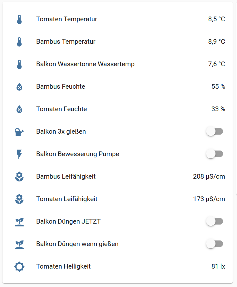
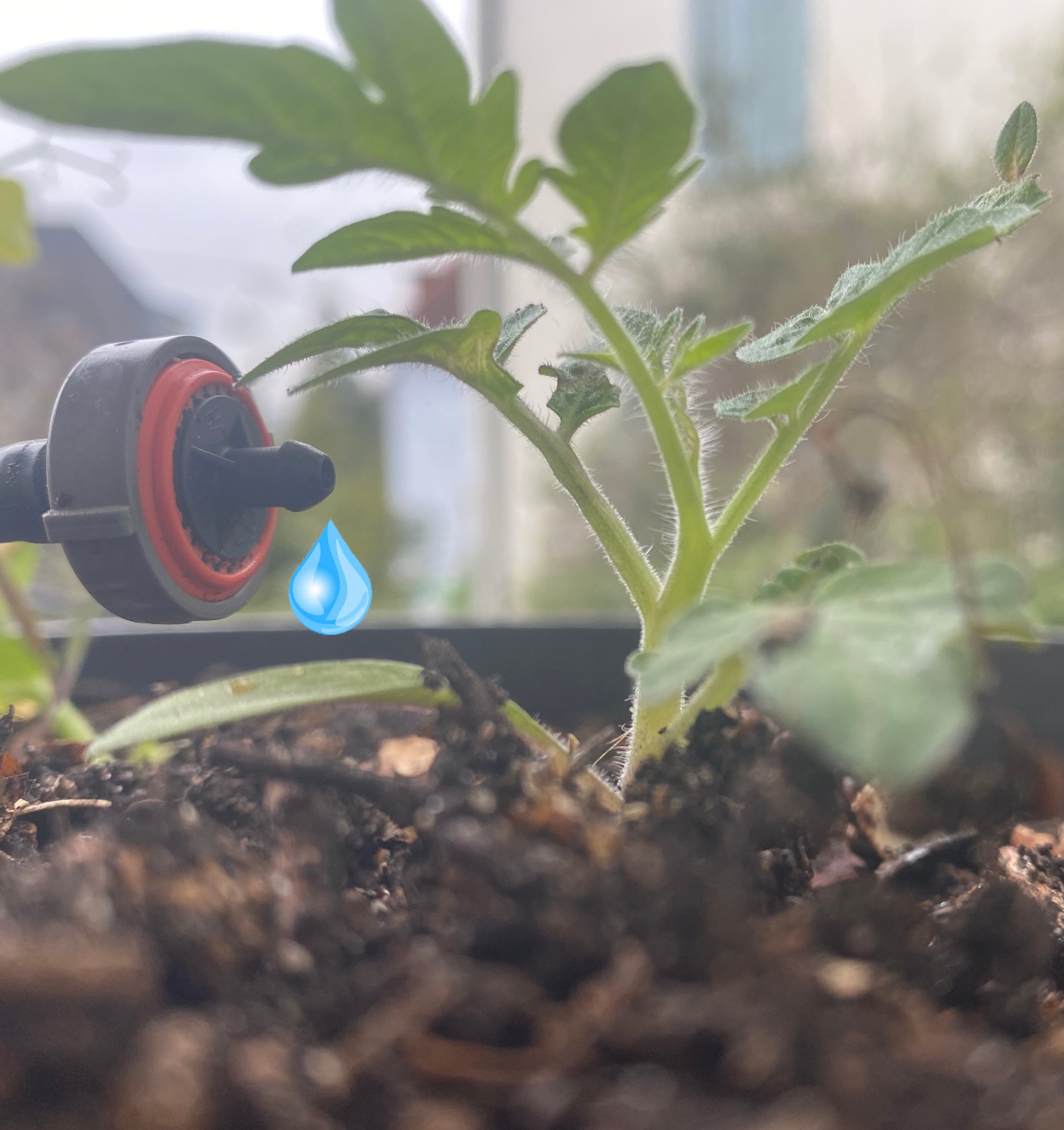
JanMy machine zoo already contains automated watering for my garden. With weather data and more sensors added plants do what they can do.
However, fertilizing was always a mystery. Well, it still is. This project tries to get it fixed. This project contains parts, electronics, and software to apply liquid fertilizer automatically.
I started with the search for an appropriate pump. A peristaltic pump looks like the ideal solution:
The pump mechanics is separated from the medium to be pumped and very small amounts of liquid can be pumped. Off the shelf, these pumps were not so cheap and not so common. And what engineering would it be to just buy it? Searching the internet for printable pumps left me underwhelmed quite a bit. Some consisted of so many parts and were even not very reliable. How about a mounting frame?
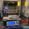
So back to the drawing board and a few iterations I came up with this 3 printed parts pump:
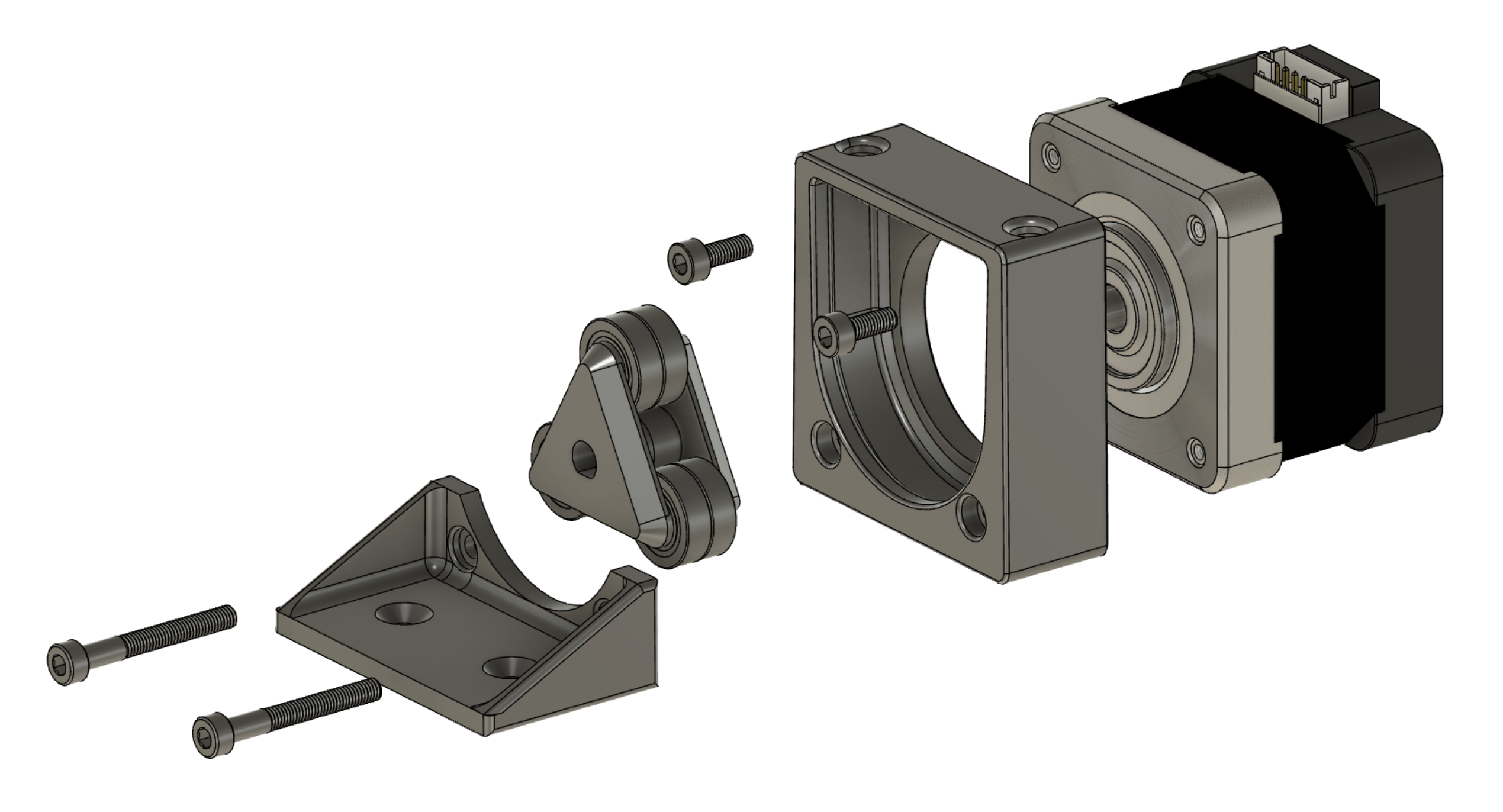
So far it just does the job. Downloadable on prusaprinters including Fusion 360 files who want to adjust. After the many iterations the tidiness of the files is a bit, well, never mind.
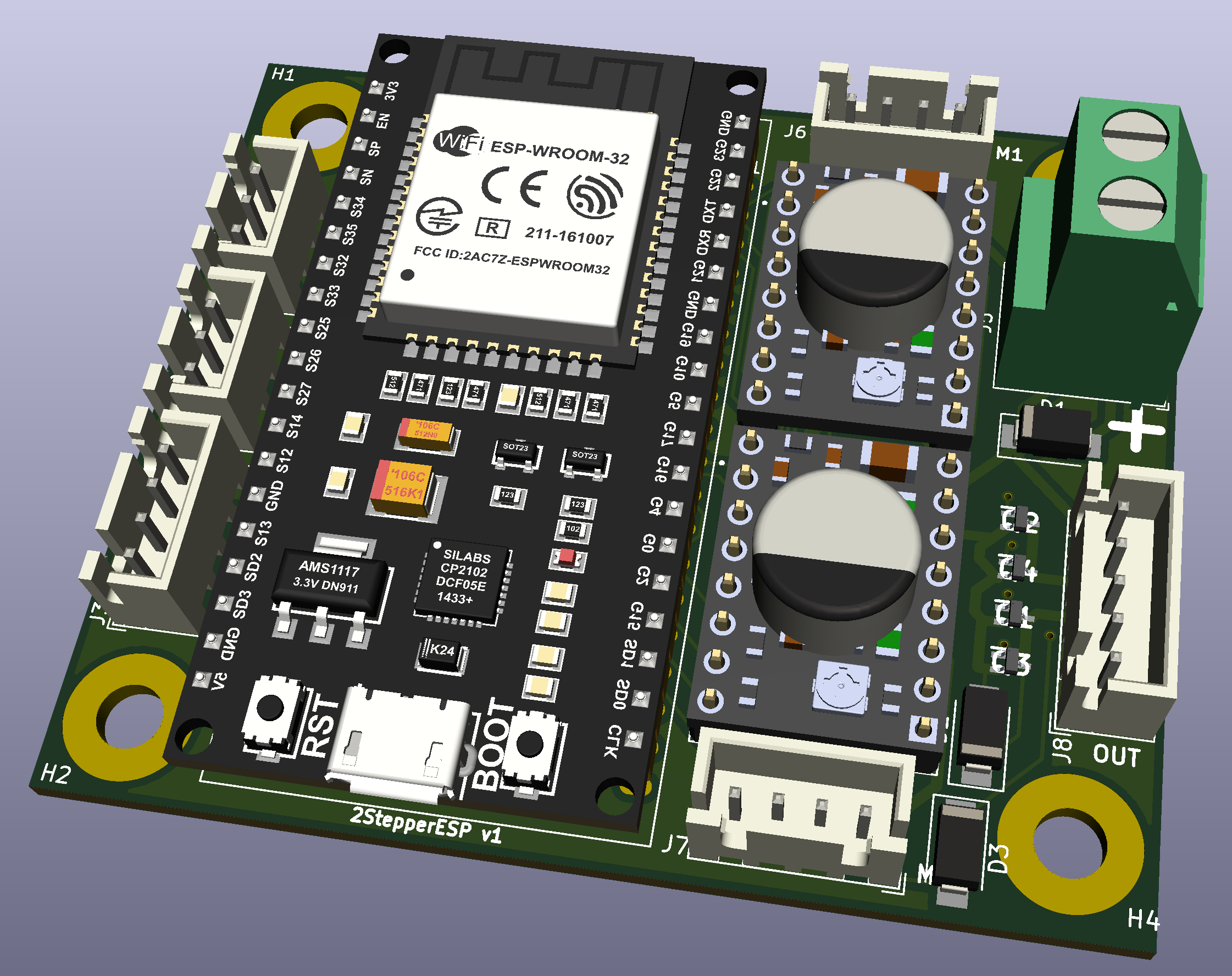
The next step is electronics. The pump is driven by a stepper motor like on most 3D printers. So I needed a PCB to host a ESP32 which could also add other sensors, relays for irrigation, and receive Bluetooth LE sensors. A board for this should be abundant, however I did not find any with reasonable size and connectors. So learning more KiCad is next. This PCB does all I need in a small form factor:
Connections are ready for:
- 2 Steppers
- 2 Aux high power channels for LEDs or so
- I2C (you never know)
- Some user inputs
- And good old Dallas temperature sensors
First PCBs arrived. How well do V1 PCBs work? They somehow do, with just some cuts and wires added. V2 is on the shared link from Aisler where you could order it right away (no affiliate sh.t), the KiCAD files should be downloadable in the files section.
My assembled PCB looks like this:
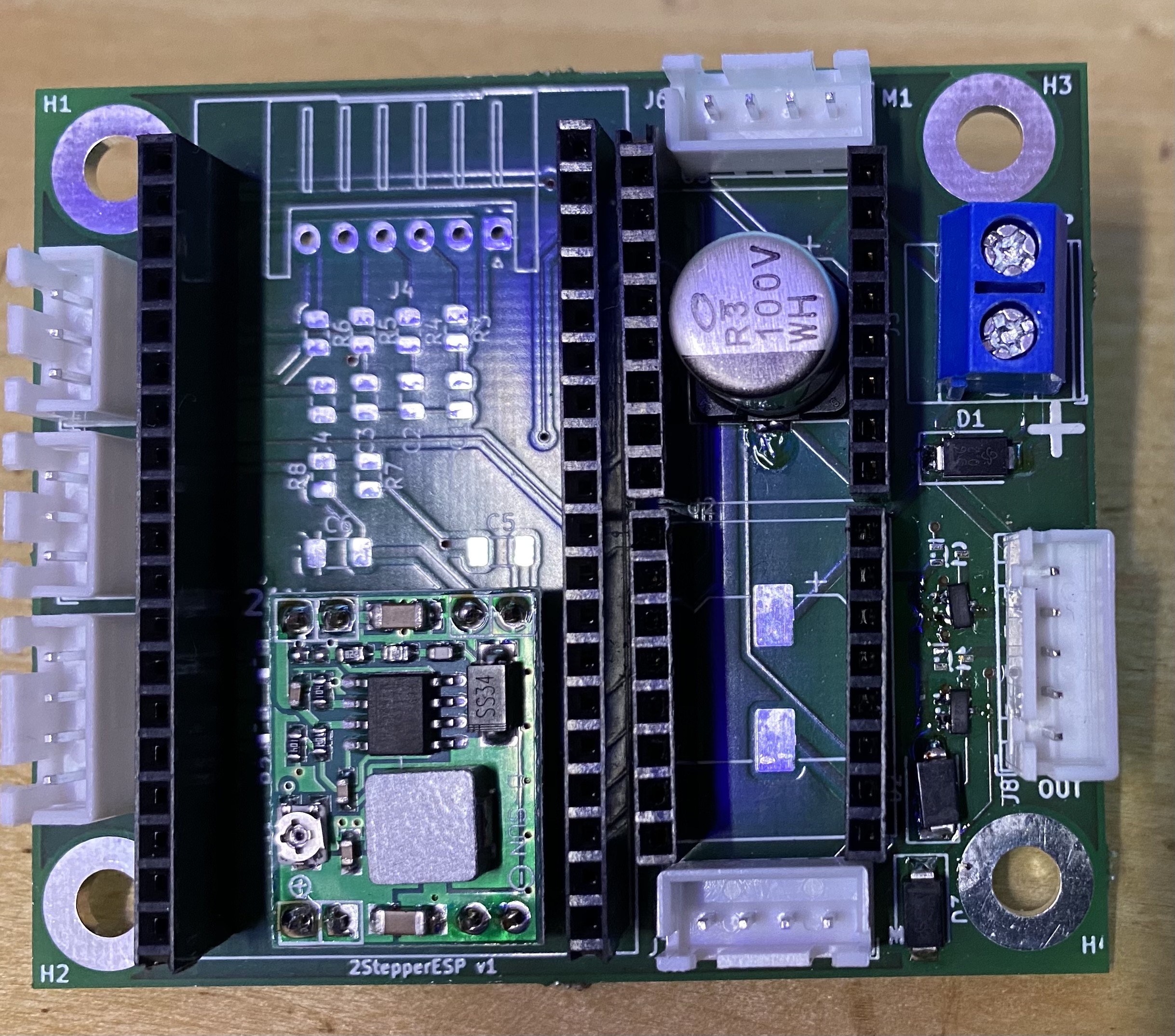
Some parts are optional, like the FETs on the right side (with way too small footprints). The diodes are for protection, if you will never ever have reversed polarity on the input they are not needed. I need them.
Things that have to be on the board:
- The DCDC converter module. search for a 3A version with 8 connection THT holes. Adjust to 5V BEFORE inserting the ESP32.
- At least one SMD 100µF 10x10 35V smd capacitor. There is a chance of frying the stepper without it.
- I love the JST XH connectors for everything but power. They are cheap and if crimped properly also very reliable.
The complete PCB:
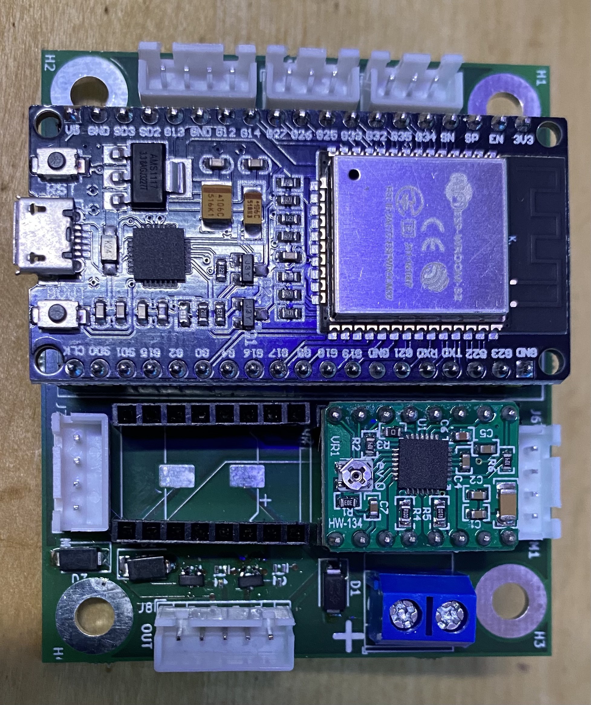
Thats all!
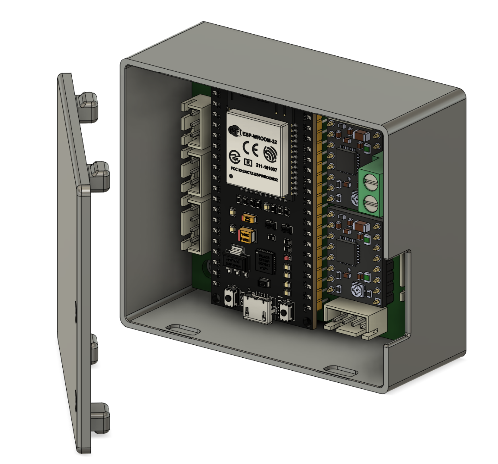
A naked PCB is bad. Especially in an environment of water mixed with highly conducting fertilizer. I still need to design a housing for each project separately. Why is there no fancy generator I know?
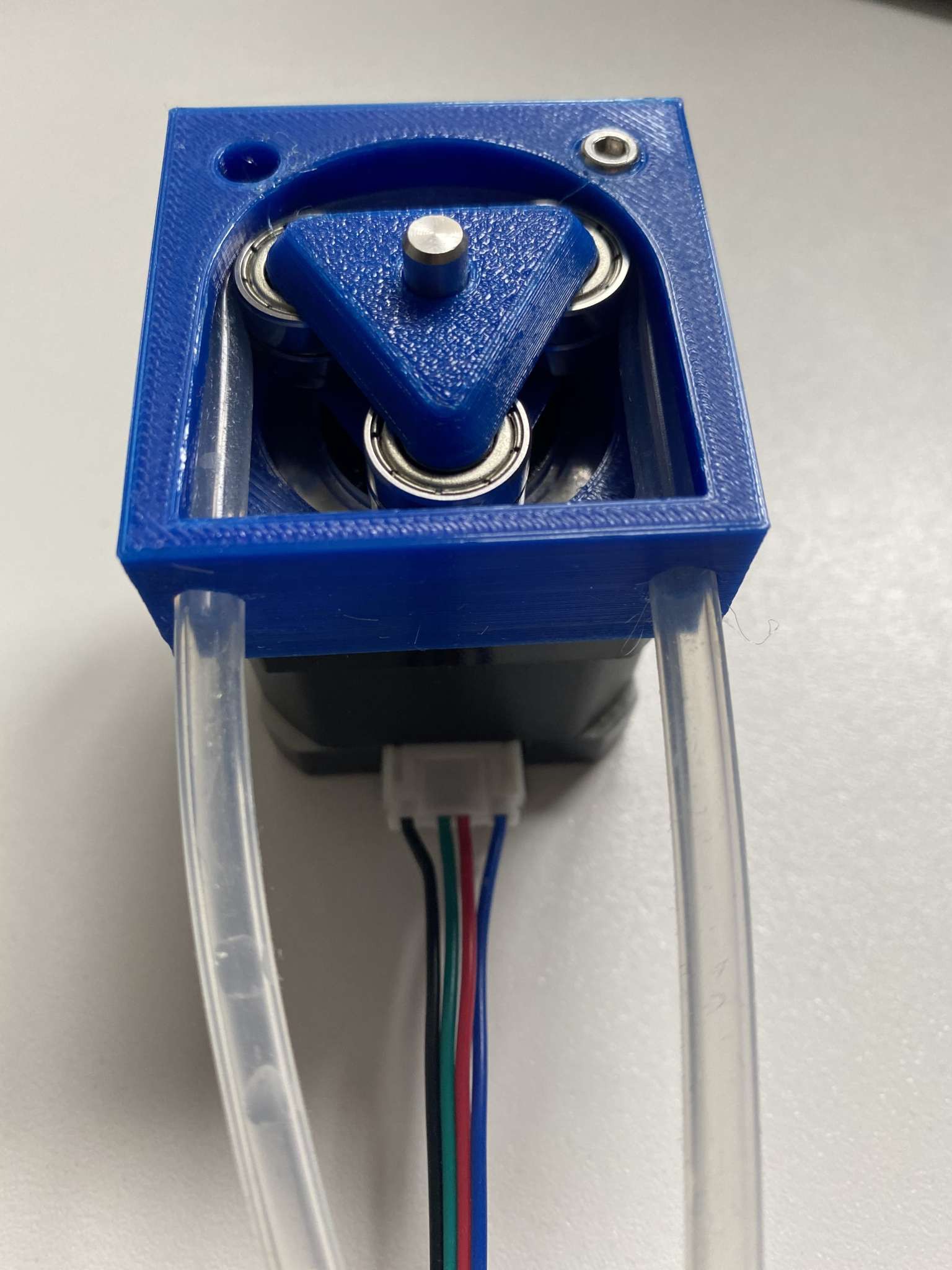
Anyway, this is the 50thiteration or so for a reliable housing. And finally: It prints, snaps close, comes apart with medium force without braking!
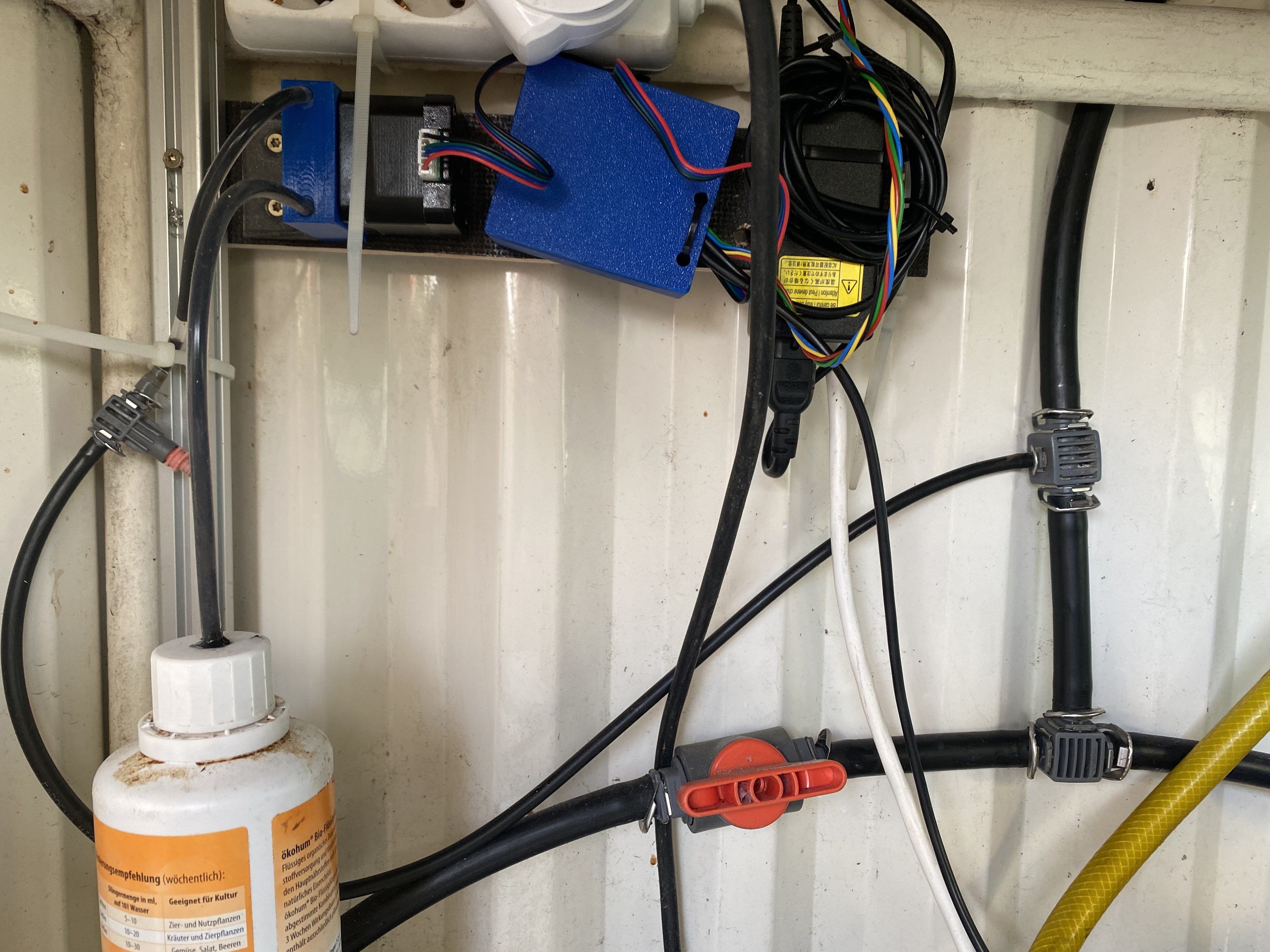
The final installation looks like this:
The rest is software. I am a lost fanboy to esphome.io. No more dealing with nasty Arduino libraries with "delay (1000);" commands. One YAML file to rule all the sensors! Integration in Home Assistant is done in a second. An example can be found in the download section.
If the summer finally arrives in Germany, we will have the biggest tomatoes ever! Definitely!
Grow!
If you want to reproduce this thing, these are the steps which really cost me time (and other things):
- Wiring of the stepper motor I messed up big times. Measure your coils on the motor (around 2 Ohms) and connect them to PCB the right way. Easy hah? EVERY cable and motor is different! Bascically one coil goes to 1A and 1B, the other coil to 2A and 2B. If it still does not spin exchange the two wires of one coil.
- Test the whole thing one more time before final installation. If you don't you will anyway.
- Some motors have the axle notched not the whole way. I added an additional spacer....


 Chris
Chris
 deʃhipu
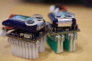
 sako0938
alright. Prusa changed the system, here the new link: https://www.printables.com/model/63883-peristaltic-pump-simple-working-for-an-automated-f