I like to start a design by making some high-level decisions about what features it will have. There’s no need to be too specific at this point, we’re just setting our overall goals for the robot.
Form. If we’re sticking with the classic self-balancing robot challenge, we’ll need two motorised wheels, one on each side of a frame — easy. We’ll make its body taller than it is wide, so it doesn’t naturally balance. Now that would just be cheating!
Style. Let’s make this a small, cute balancing robot, roughly the size of a human hand. What would make it even cuter? A little LED emoji face, of course! And while we’re at it, we’ll give it a speaker so it can chirp at us.
Function. If we’re going to take the time to make our own robot, we might as well give it a few extra functions on top of the basics. Let’s give it a camera and a microphone, so we can play around with autonomy later. And, just to be different, we’ll give it a pair of servo-powered forks, so it can pick up itty bitty things and carry them while balancing. What could go possibly wrong?
Once you’ve chosen your features, it wouldn’t hurt to do a couple of sketches to visualise what you’re creating. It’s easier to work towards the end goal when you can actually see what you’re aiming for. Plus it helps you think about part positioning
Finding the right components
With the concept in mind, we can now start speccing and picking our components. The basic bits we’ll need are a microcontroller (for low-level control of the balancing), a single-board computer (for the camera, microphone, speakers and high-level control), a battery, an inertial measurement unit (to measure the robot’s angle) and, of course, motors. There will also be a few standard components we’ll need like voltage regulators, motor drivers, etc, but we’ll get to that later.
As we go through each piece and identify the specific component we want, we should always remember to keep track of the communication protocols and power requirements we need. For example, if we pick an inertial measurement unit (IMU) that communicates with I²C and requires a 3.3V power supply, we need to ensure our microcontroller has I²C capabilities, and that our system provides access to a 3.3V power supply.
Getting specific and narrowing it down
To start with, we’ll decide on a battery to power our little friend. This will likely be the biggest and heaviest component, making it a good starting point for identifying requirements for the rest of the system. Looking for a battery with a good power density (low mass, high capacity), I came across a 2-cell LiPo from HobbyKing which will do the job nicely. It’s the right size, and will give us a constraint for the robot’s minimum width.
I decided to use stepper motors to drive the wheels, allowing precise control of the wheel speed without needing encoder feedback from a DC motor, or an additional control loop to maintain speed. We’ll use two little 12V geared stepper motors, two stepper driver boards and two step-up voltage converters to raise the battery’s 7.4 volts up to 12V.
The Pi Cam seems like a natural choice of camera, and we’ll pick up a little speaker, amplifier and an I²S MEMS microphone. For the face, we’ll use an 8×8 DotStar Matrix, and to power the forks, an SG90 servo. Lastly, we’ll go with an MPU6050 6-axis inertial measurement unit to track our robot’s orientation.
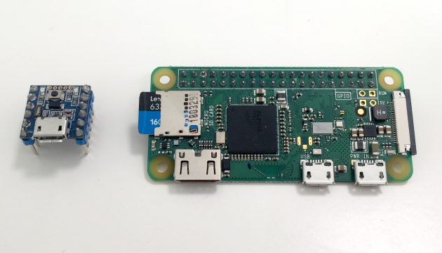
For the sake of keeping everything small (and cute), we’ll go with the Nerdonic Exen Mini for our microcontroller — a coin-sized, Arduino compatible board with a Cortex M0+ CPU. It will talk to the motor drivers, the IMU and our single-board computer, for which we’ll use a Raspberry Pi Zero W. With such a big community around the Raspberry Pi, we’ll have a solid base to work from. Plus it’s a very compact computer that we can connect to wirelessly with WiFi and Bluetooth. We’ll also need a 5V voltage regulator to give us a consistent power supply for the Exen Mini and the Pi.
Left: Exen Mini microcontroller. Right: Raspberry Pi single-board computer.
I decided to use stepper motors to drive the wheels, allowing precise control of the wheel speed without needing encoder feedback from a DC motor, or an additional control loop to maintain speed. We’ll use two little 12V geared stepper motors, two stepper driver boards and two step-up voltage converters to raise the battery’s 7.4 volts up to 12V.
The Pi Cam seems like a natural choice of camera (we'll need an adapter to use it with the RasPi Zero), and we’ll pick up a little speaker, amplifier and an I²S MEMS microphone. For the face, we’ll use an 8×8 DotStar Matrix, and to power the forks, an SG90 servo. Lastly, we’ll go with an MPU6050 6-axis inertial measurement unit to track our robot’s orientation.
The glorious bill of materials
While we’re doing all our research and speccing, it’s a great time to keep a spreadsheet open. This is where we’ll create our bill of materials (BoM). It’s a good base from which to estimate, and summarise, the weight, price, quantity of components and exact specifications of our design. Note that this is not a comprehensive BoM, moreso a glorified shopping list. You’ll find yourself coming back to this spreadsheet very often, so it’s a worthwile use of your time. Here’s how mine looked:
I’ve left the individual prices out of the above example, as they’re subject to change, but the total came to about $200 AUD. Keep in mind that most of this cost was due to all the extra features I decided to include (e.g. the LED matrix was around $60). We can reduce this cost to around $100 AUD if we aim solely for the balancing features. We’re also weighing in fairly light at just 116g for the components, which our selected stepper motors should be able to push around without too much trouble.
Great! We’ve got a shopping list for one wheely boy. A wheely cute boy. Ahhh puns, I’ll never tyre of them.
Designing the circuit
To keep the robot neat and compact, I chose to design a printed circuit board (PCB) to connect all the electronics. This isn’t by any means necessary; you can create a circuit prototype easily enough by soldering to perfboards. We’re going to house our components in female header pins, so we can easily remove or replace them if something goes wrong, or for debugging purposes.
I used Autodesk EAGLE for this project. There are plenty of tutorials available on PCB design with EAGLE and other programs, and it’s not too tricky for a beginner to get acquainted with. There are also open source alternatives available such as KiCAD, which I use as well.
Making the right connections
We’ve already picked our specific components and have them listed nicely in our BoM, so now we want to figure out exactly how they’ll all connect to each other. Google is your friend here! You can find datasheets for your components, which will provide descriptions of pin functions and example usage, and often these are summarised on the product page itself.
What we want to do is create a schematic in our CAD software. This is a diagram that will depict each of our components as blocks with input and output pins, and we can draw connections between our pins as desired. These blocks are called symbols, and for common components you can typically find these available for download online. If you find yourself with an uncommon component, it’s easy enough to create a custom symbol for it.
The schematic will provide a good overview of our circuit, and gives us a good point of reference for checking our connections against the datasheet specifications. It’s a good idea to segregate your schematic into different sections and label them based on functionality. Keep in mind that the layout of your schematic simpy describes component connections and has no bearing on the physical placement of components — that’s where the PCB layout comes in.
Laying down some tracks
Now that we’ve identified all our connections, we can start working on the PCB layout. This is the design for the physical layout of the PCB, including pads (points we solder our pins to), tracks (the wires connecting pads together), and mounting holes. We’re going to make a simple 2-layer PCB, meaning we have two surfaces to lay tracks and pads on.
We can download footprints for our individual components, just like we downloaded their symbols (often they come together in a package). Again, if we can’t find a footprint, we can create our own custom one, where we make use of the components’ datasheets to find the required pad layout and dimensions.
When you first begin creating the PCB layout, the software will usually dump all your components on the screen, and a ratsnest of lines will be strewn about between them, indicating which pins need to be wired together. A good way to begin cleaning up this mess is to refer to your schematic, and identify pairs of components that have the most connections between them. It often makes sense to place these physically near one another, to minimise the length of tracks between them.
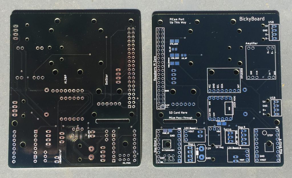
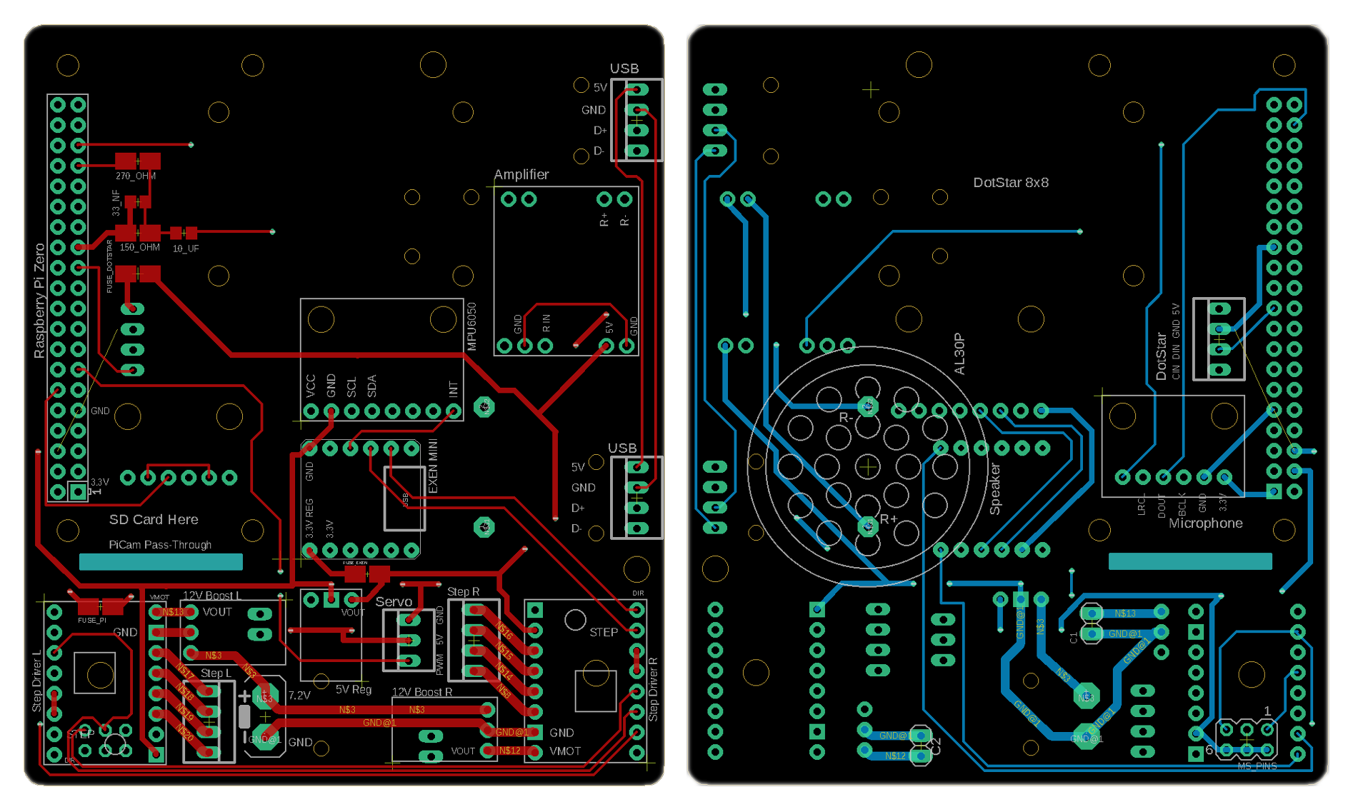
My partner put together the schematic for our balancing robot, and I created the layout — which turned out like this:
Left: Top layer. Right: Bottom Layer.
It can be a bit intimidating to commit to laying tracks between components at first, but sometimes you just need to jump in and make a start. You can always remove it later if you need to reorganise your component footprints, in fact it’s highly likely you’ll need to readjust as you go — I certainly did.
Going beyond the bare essentials
In addition to wiring up all the essentials, I added a few extra features to the PCB to make life a little easier.
2×3 set of header pins to allow configuration of the stepper driver microstepping modes. Microstepping allows you to increase your stepping resolution, by
decreasing the rotation of your stepper motor output per pulse sent to
the driver. Each driver has three pins, MS1, MS2 and MS3, which can be
pulled high in different combinations to change the setting. With these
MS pins connected to our 2×3 header pin set, we can simply set the
microstepping mode by plugging jumper caps onto the pins, thereby
shorting them and connecting them to a logic-high voltage.
PWM audio circuit. The Raspberry Pi Zero W has no in-built audio output functionality, so I had to add a small circuit to
provide this, making use of one of the Pi’s PWM outputs. There’s a great tutorial from Adafruit
which explains how to set up the audio in this way. I wanted some more
experience with SMD component soldering, so I used SMD resistor and
capacitor footprints for the circuit.
Self-resetting fuses. I’ve added a number of these around the board to protect some of the
more important components, namely the Raspberry Pi, Arduino and the
DotStar Matrix (which can draw a lot of current).
Holes in the board. (How impressive.) There are mounting holes for components, a routed
slot for the Pi Cam ribbon to pass through to the opposite side of the
board, and some holes to pass twist ties through, to allow for
strain relief of important wires (such as the main power leads). Never
underestimate the importance of strain relief!
Printing the circuit boards
There are a number of manufacturers available who can accept your PCB design files and make your board for a reasonable price. I went with PCBWay to get mine manufactured, and it’s a pretty simple process.
You’ll need to output Gerber files from your CAD program, which describe the different layers of the PCB and their geometry, which the manufacturers need to produce it for you. For example, there is a layer called “Edge Cuts”, which describes the outer boundary shape of your PCB; this is how they know how to cut the board out.
Once you’ve got your files produced you can upload them to your manufacturer’s quote page, specify your number of layers, what colour you want your boards, and then they’ll review it. My boards shipped pretty quickly and turned out well — as you can see above.
Giving the bot a body
With the PCB complete and the electronics acquired, it was time to design the physical pieces that would make up the body of the self-balancing robot. Namely, the frame, wheels and forks. I used SolidWorks to model the pieces, with the intention of 3D printing the design. If you’re not a student or don’t have access to licensed software, you can use a free alternative such as FreeCAD.
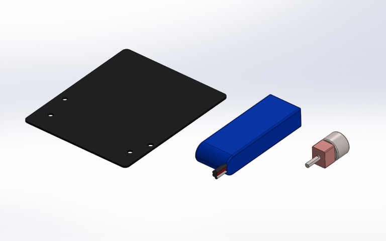
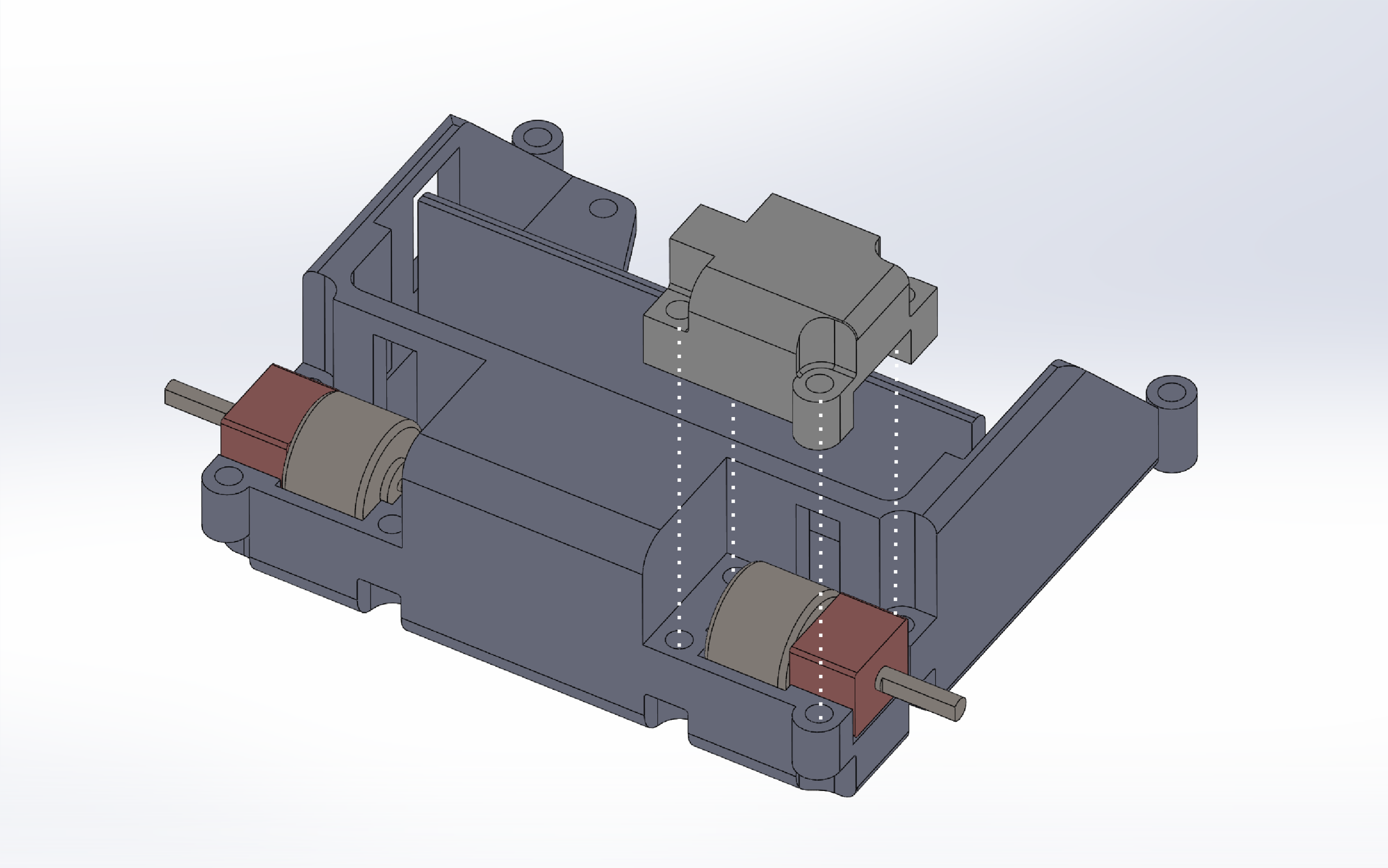
Going with the top-down approach, a good starting point is to identify which of your components are going to constrain your design the most. For our self-balancing robot, this would be the printed circuit board, the battery, motors and servo. We’ll make some simple CAD mockups of these components to start with, so we can arrange them in our design and ensure a good fit.
CAD models of printed circuit board, LiPo battery and stepper motor.
Taming the frame
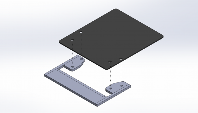
The first piece we’ll model is our frame. We want our PCB to attach to the frame vertically, so we’ll design a couple of flat mounting pieces with holes that line up with the PCB’s mounting holes. These will attach with M3 fasteners, so we’ll make our holes a little wider than 3mm.
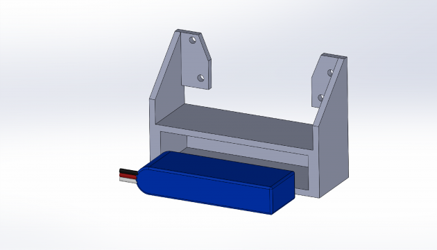
Below the PCB, we’ll make a housing for the battery. For the time being, this can be a simple rectangular slot with wriggle-room for power leads and such. Later on, we’ll add a battery cover to secure it.
As we start modelling housings for our components, it’s also a good idea to think about where the wires will route up to the PCB, otherwise we’ll end up with a tangle of free-hanging wires. We want to make a self-balancing robot, not self-balancing spaghetti. As I went along, I modelled additional slots and holes for wires to snake up through the frame to the PCB, via the back of the battery housing.
Vamping the clamps
For the motors, we’ll attach them by making a pair of clamps. The frame will have cutouts on either side which perfectly fit half of the motor casing. We’ll then make two separate pieces which bolt onto the frame and hold the motor tight in place, like this:
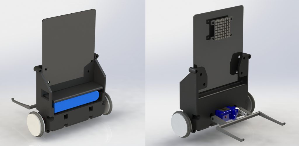
Finally, we’ll make a little set of forks so he can pick up some very light objects. Oh and some wheels, those would be helpful. For the wheels, we’ll 3D print a couple of slotted disks, so we can slip some O-rings around them as DIY tyres. With the assembly finished, our design looks like this:
What a cutey! Time to bring this fellow into the real world.
3D printing the pieces
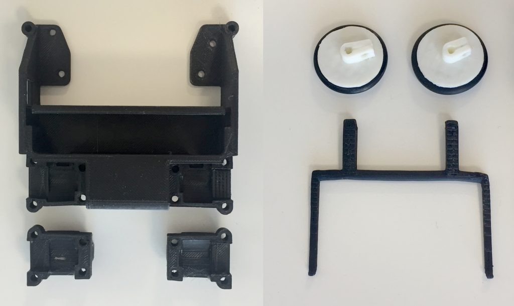
Before printing the whole frame, I found it useful to isolate certain parts of the design and print them first, to test how well they would fit. For example, I chopped away most of the frame and printed solely the internal section of the motor housings, which I then tested with the physical motor to assess the fit. This can save you a lot of time and headache, unless you’ve already got your print tolerancing down to a tee.
Left: Frame and motor clamps. Right: Wheels (with O-rings) and forks.
I used a glass-bed Prusa i3 clone to print my parts from black PLA+, using Cura as the slicer. The prints were run with the nozzle at 180°C and the bed at 70°C, with a 0.5 thick, 3mm offset raft. You can see above how the second try turned out (I’ll save your eyes from the atrocious first attempt). Not too shabby.
Trembling for an assembling
We’re so close putting this bad-boy together! We just need to crimp a few leads, solder all our bits and bobs onto our freshly squeezed PCB, and attach it to the frame. I’ll spare you the soldering montage.
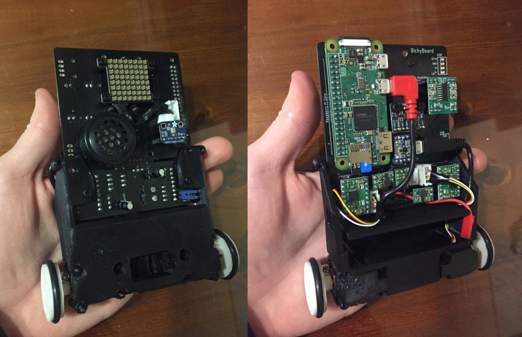
After installing the board and motors with M3 fasteners, and inserting all the components into their sockets, here’s what our little guy looks like:
Now we’re ready to start programming, getting his wheels moving and putting a smile on that 8×8 face! The servo and forklift will be a stretch goal once we get a little further through the project. Hopefully this was helpful in giving you a bit of insight into how to design a robot from scratch!
For a detailed tutorial about the coding and testing, see the project logs :)
P.S. Save yourself from my mistakes
I’m going to jump ahead temporarily here and let you know a couple of mistakes I made during this process, in hopes to save others from making the same errors.
Pull-down/pull-up resistors. Don’t leave your signals floating! This can cause unexpected behaviour for your electrical components. When we designed the PCB, we didn’t include any pull-down resistors on the wires leading from the Arduino to the stepper motor driver inputs. What does this mean? If the Arduino hasn’t specifically set any of its outputs, the wires have no constant voltage level, and will fluctuate wildly with noise. This caused my stepper motors to randomly twitch when the Arduino hadn’t been set up.
Check the logic-levelvoltage requirements of your components. The 8×8 DotStar Matrix requires 5V for its logic, but I connected it to the Raspberry Pi, which uses 3.3V for its digital outputs. Silly mistake. I had to wire in a logic-level converter board to fix this.
Match your logic power supply to your digital control logic voltage. This one was a little more subtle; the stepper driver boards stated that they accepted 3 – 5.5V for their logic power supply. Great, so I can use my Arduino’s 3.3V digital outputs to control it? Correct, but not when you power the stepper driver boards from your 5V regulator! The boards will use this 5V logic power supply input as a reference voltage for determining a logical high. So to use 3.3V outputs to control them, you need to put 3.3V on the logic power supply inputs.
 Ben Steer
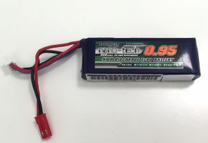
 Left: Top layer. Right: Bottom Layer.