 Ben Steer
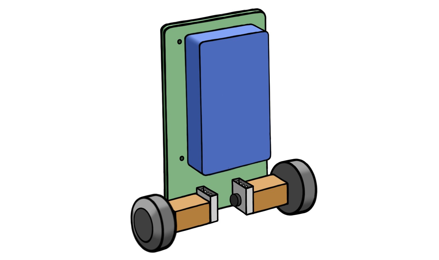
After reflecting on the first version of our mini self-balancing robot, I was wondering how I could improve the design and perhaps make it even smaller… We’re going to do an exercise in system design - which I love almost as much as creating robots - and come up with a plan for a balance-bot version 2!
Heads up - this lil’ post contains some sponsored content from PCBWay.
Changes in the New Design
We’re going hard on reducing the mass of this bot; as a result, some of our components are going to change considerably. Let’s talk through the new design:
- Chassis: We’re going to ditch most of the 3D printed parts that made up the body of the previous robot, and we’ll try to mount components directly to the PCB as much as possible. There may still be some 3D printed parts around the wheel assemblies, and the wheels themselves.
- Minimal Features: I was overly ambitious with the previous robot, trying to add a camera, face, microphone and forklift (what a silly boy). We’re going barebones on this one and focusing on balancing, driving and turning nicely.
- Surface-Mount PCB: Instead of the previous board, where we attached pre-made modules to our PCB using through-hole legs and headers, we’re going to have SMD mount as much as possible. The microcontroller(s) may still be mounted as modules, depending on how much work we want to put into the PCB design. Either way, this will reduce mass and let us make the board even tinier!
- Raspberry Pi Swap-out: Instead of having a RasPi Zero, which is relatively big, we’ll go for a Wi-Fi capable microcontroller (MCU) that’s a bit more compact, like an Arduino Nano 33 IoT (which also includes a 6-axis IMU on board if we wanted to swing that way).
- Steppers to DC Motors: Instead of our micro metal geared stepper motors (which weren’t quite beefy enough for the job), we’ll go with some brushed 6V DC motors with gearboxes and encoders, like these. This will require adding some motor controller elements to the PCB, instead of stepper driver modules. However, if we go with 6V, we won’t need 12V boost converters any more - we can draw power directly from the battery, or run them through some (relatively) high current voltage regulators.
- LiPo to LiFePO4: Working with LiPo batteries makes me anxious lol - this time we’ll use a 2-cell LiFePO4 battery, which is less energy dense, but safer to work with.
- Battery Indicator: It would be super handy to add a little array of LEDs to the board to indicate the remaining battery life. Last time, I had to wire and stick a little alarm board to the side of the bot, which was pretty annoying to do every time I swapped the battery out.
The other elements of the balance bot will be similar to the original, including a dedicated MCU for balance control, 3D printed wheels, an IMU, and voltage regulators for the MCUs. Next, let’s figure out what this thing will look like.
Physical Layout
I’ve added a few sketches here for how I envisage the new robot being configured. Here you can see the general layout - the PCB is really the core structural element holding the robot together. Instead of having a plastic chassis with the battery mounted in an enclosure, we’ll have the battery mounted vertically on the back of the PCB with a very light frame to hold it in place. This means we can make the robot narrower, bringing the wheels closer together and reducing the overall dimensions of the robot. The motor and encoder assemblies will be mounted directly to the board with some 3D printed clamps/mounts and some pre-planned holes in the PCB.
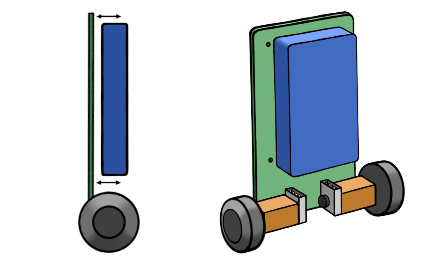
From the side view, you can see that the center of mass of the robot will be offset from center of the motor/wheel axes. We want the robot to be as statically stable as possible, which in our case, means it can nearly balance on its own if there is no outside influence. To help with this, the new design will allow the distance between the battery mount and the PCB to be customised, perhaps using some adjustable screws - similar to how one calibrates the height of a 3D printer bed. This way we can precisely tune the static stability of the robot, which will make life a lot easier when it comes to programming the control system. Alternatively, the offset of the wheel/motor assemblies could be adjusted instead.
With all this considered, I reckon the robot should come out to roughy 10 x 7 cm in size! That’s pretty tiny, and very cute.
PCB Design
While my previous board was pretty basic, and I could have done something similar with perfboards and wires, the benefits of having a custom PCB really shine when you start doing SMD designs and trying to make very compact boards. We’re going to need that if the balance bot v2 is going to be extra small.
For the first self balancing robot, I used PCBWay to have my custom PCB designs manufactured. You mightn’t think that custom manufacturing services would be affordable for low budget prototyping projects, but PCBWay is actually very hobbyist-friendly. I ordered 10 of my custom boards - which were 2-layered and included some milling operations - and the whole service (including postage to Australia) only came out to around $30 AUD. Depending on where you're located, it’ll probably end up even cheaper than that.
The whole process for ordering your boards is super easy and all done online - you can upload your design, choose your board settings and get an instant quote before committing to anything. They were actually very helpful and emailed me after I placed my order to confirm some aspects of my design, before going ahead with the manufacturing, which I must say I didn’t expect.
The boards turned out great - they were great quality and I was super excited to see my designs come to life! I was happy that the only problems I had with the boards were from my own bad design decisions (e.g. not adding pullup/pulldown resistors to most of my components lol) and not from the service. If I go ahead with this new design, or if anyone else wants to try building it, I’d definitely recommend PCBWay.
The New Board
On the back of the board (shown in the sketch below), firstly we have our motor drivers at the bottom, close to the wheel assembly mounting holes. These may or may not include a 6V voltage regulator alongside them. We'll have pads there to solder directly to the leads which connect into the motor/encoder boards. The drivers will have tracks running up to the control MCU to provide encoder input and receive motor commands.
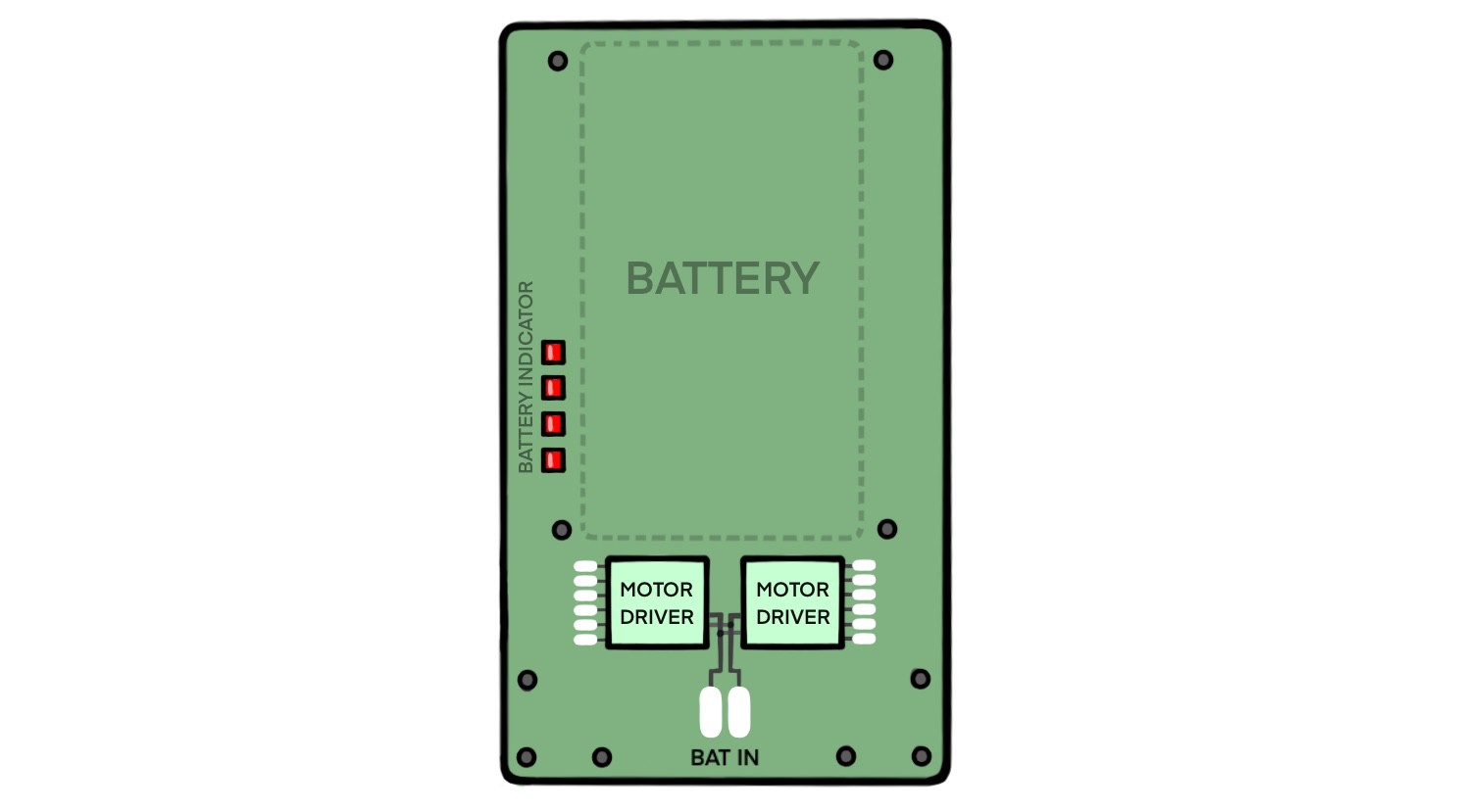
There are two large pads to add the connections to the battery leads, and to the side you’ll see the little LED array to indicate the remaining battery life. This will have some additional, self-contained circuitry to handle the LED control based on the battery level (alternatively, they could be controlled from the MCU).
On the “front” face of our board (shown below), we’ll have our microcontrollers, and mount them near the edges so we can connect programming cables easily. On one side we have our Wi-Fi-capable MCU, and on the other side the our little dedicated control MCU and its connected 6-axis IMU. We also have the 5V voltage regulator to power our MCUs. We’re going to try to distribute the components so the center of mass lines up roughly with the sagittal plane of the bot.
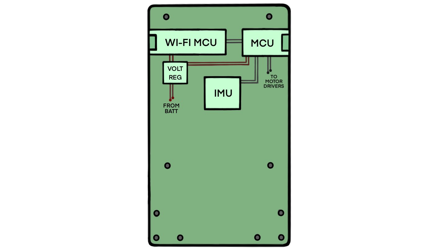
You can see we have mounting holes at the bottom to attach the motor assemblies, and some holes around the perimeter to attach the battery frame.
Going Forward
Well, I think this is a pretty reasonable design for a tiny self-balancing robot. Will I end up building it? Maybe :P But if anyone out there wants to take this design and properly flesh it out, and maybe even build it, be my guest! I would love to see this thing in action. Happy hacking!
Discussions
Become a Hackaday.io Member
Create an account to leave a comment. Already have an account? Log In.